|
|
Install the Server Memory |

Use the following tasks to install RAM DIMMS from memory kits in the server.
Ignore steps in this procedure that don't match your installation flow.
Examples:
- If the server is already powered off, skip the "graceful server fail-over" and "power off" procedures.
- If the server is not installed in the rack, ignore the "removing the server from the rack" procedure, etc.
In addition, do not perform the "Next Steps: section if you have not yet completed installing the system.
Safety Considerations
Review the following safety instructions before installing or removing server components.
WARNING: Do not attempt to lift the server by yourself. Avoid injury by getting others' assistance any time you need to lift the server.
WARNING: Do not work on the server with the cover removed while the server is powered on. Opening or removing the server cover while the server is powered on may expose you to a risk of electric shock.
Caution: Do not operate the server without the cover for a duration exceeding five minutes. Operating the server without the cover can result in component damage.
Note: Always use a static mat and static strap while working on components inside the server.
Note: To ensure proper operation and cooling, all bays in the server must be populated at all times with either a module or with a blank.
Complete the following tasks to prepare for memory module installation.
Note: You do not need to perform the server fail-over operation at this time if continuing the installation procedure.
Access the command line of the node currently operating as primary, and initiate the graceful fail-over to the server node currently acting as secondary:
- Open an SSH connection to the appropriate server and use the IP address assigned to the node on the Management or LAN Client network, or use the Service Port IP address, if connected to the Service Port.
Service Port IP addresses (if used):
Note:
Node 2
- Log in to the server node with the following credentials:
- User name:
stornext - Password:
<stornext user accountpassword>Note:
passwordis the default password for the stornext user account. If the password has been changed, use the current password.
- User name:
- Enter
sudo rootshto gain root user access. - Enter the password for the
stornextuser account again.
- Confirm that the server node you are connected to is operating as the primary. Enter:
- Verify the output is (bold text used for clarification):
- On the node operating as the primary, initiate an HA fail-over to the node operating as the secondary.
- Verify the node has failed over. Enter:
- Verify the output is (bold text used for clarification):
snhamgr -m status
:default:primary:default:running:
This indicates the node you are connected to is running, and is set as "primary", and that the secondary node is currently "running".
Note: If you have NFS-HA enabled, click here for the instructions to stop NAS prior to using this command.
For CentOS7-based systems (, , , and systems), enter:
systemctl stop cvfs
Note: The systemctl stop cvfs command does not provide any command-line status feedback on the progress of stopping cvfs operations. You will need to be patient and wait until you again have access to the command line prompt.
Wait until the secondary node becomes the primary. (Time may vary.)
snhamgr -m status
:default:stopped:default:primary:
This indicates that the node you are connected to has "stopped" as primary, and that the node previously operating as secondary is now operating as "primary". If this is not what is shown, wait and enter the snhamgr -m status command again.
You can leave the SSH connection to this server node running if you will access this server again soon.
You will need to power off a single server node when you need to perform a CRU or installation procedure on the node, or to move a single node to a different location within a rack (Quantum recommends nodes are collocated in the same rack), while allowing uninterrupted metadata operations on the StorNext system.
Caution: For systems running NAS with NFS-HA enabled, DO NOT stop cvfs on the system before first stopping NAS. Learn more about this issue before you continue with this procedure.
Do the following to power off a single server node:
- Open an SSH connection to the appropriate server and use the IP address assigned to the node on the Management or LAN Client network, or use the Service Port IP address, if connected to the Service Port.
Service Port IP addresses (if used):
Note:
Node 2
- Log in to the server node with the following credentials:
- User name:
stornext - Password:
<stornext user accountpassword>Note:
passwordis the default password for the stornext user account. If the password has been changed, use the current password.
- User name:
- Enter
sudo rootshto gain root user access. - Enter the password for the
stornextuser account again.
- If you are connected to the node currently acting as the secondary, or for a single-node system, continue to step 11.
- Wait until the node currently acting as primary becomes the secondary (time may vary), and leave your SSH connection to this node open.
- Open an SSH connection to the node now operating as the primary. Confirm that the node is operating as the primary. Enter:
- Verify the output is (bold used for clarification):
- On the SSH terminal session for the secondary node (may have previously been running as primary), power off the server. Enter:
- If needed, remove power cables from the node.
However, if you are connected to the node currently acting as the primary, stop cvfs.
Note: If you have NFS-HA enabled, click here for the instructions to stop NAS prior to using this command.
Enter:
systemctl stop cvfs
Note: The systemctl stop cvfs command does not provide any command-line status feedback on the progress of stopping cvfs operations. You will need to be patient and wait until you again have access to the command line prompt.
snhamgr -m status
:default:primary:default:stopped:
"primary" indicates that this node is operating as primary.
systemctl --no-wall poweroff
Note: You need to use the systemctl --no-wall poweroff command to properly power off the server node. This command is new for CentOS7. Do not use the deprecated poweroff command on Xcellis Workflow Director servers, since it causes issues with restarting the server.
You will know the node is powered off when your monitor goes blank, or you lose your connection to the node.
Note: For servers running a release of StorNext prior to StorNext 5 Release 5.1, a RAS ticket on servers with open manage prior to 7.4 may be generated when one of the server nodes is powered off. This RAS ticket, which indicates a failure of the appliance, is incorrect. There is no loss of functionality if one node is shut down during the servicing of that node.
- Remove attached peripheral cables.
Note: Label peripheral cables prior to removing the cables to assist with attachment after working on the server.
- Remove power cables.
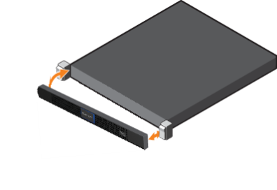
- Push the bezel latch up and pull the left end of the bezel outward, away from the server node.
- Detach the right end of the bezel, and remove.
Figure 1: Remove the Front Bezel
Remove the server from a rack as follows:
WARNING: Because the chassis weighs 33.08 lbs (15.01 kg), two people are required to lift it.
- If not done previously, remove all power, Ethernet, and Fibre Channel cables from the back of the server.
- Hold the power button in at least 20 seconds to discharge all of the condensers before opening the server.
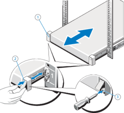
- If used, remove the screws under each latch with a #2 PHILLIPS® screwdriver (3) which secure the server to the front of the rack.
- Facing the front, locate the slam latch on either side of the server (1).
- The latches engage automatically as the system is pushed into the rack and are released by pulling up on the latches (2).
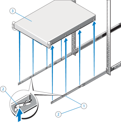
- Locate the lock levers on the sides of the inner rails (1).
- Unlock each lever by rotating it up to its release position (2).
- Grasp the sides of the server firmly and pull it forward until the rail standoffs are at the front of the J-slots. Lift the server up and away from the rack and place it on a level surface (3).
Note: If not done previously, label the cables so they can be easily identified when they are connected back to the server after the replacement procedure.
Figure 2: Unlocking the Server Node Rail Latches
WARNING: Because the chassis weighs 33.08 lbs (15.01 kg), two people are required to lift it.
Figure 3: Pulling the Server Node From the Rack
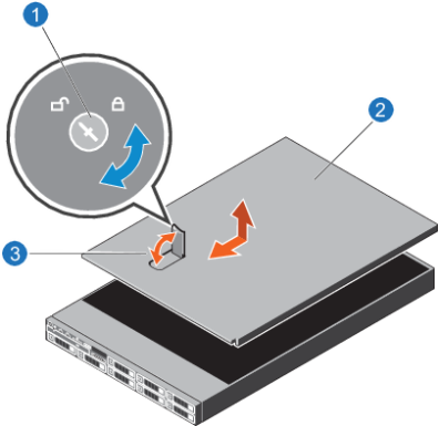
- Turn the latch release lock to the unlock position.
- Lift the cover release latch and remove the server cover.
Figure 4: Remove the Server Cover
|
1. Latch release lock |
|
2. Server cover |
|
3. Latch |
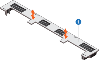
Caution: Never operate your system with the cooling shroud removed. The system can get overheated quickly, resulting in system shutdown and data loss.
Figure 5: Remove the Cooling Shroud
|
1. Cooling shroud |
Hold the touch points as indicated in the image above, and lift the shroud away from the server.
Note: The following applies to both memory modules and memory module blanks.
- Locate the appropriate memory module socket.
- Release the memory module or blank from the socket by simultaneously pressing the ejectors on both ends of the memory module socket.
Figure 6: Removing a Memory Module
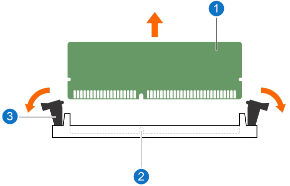
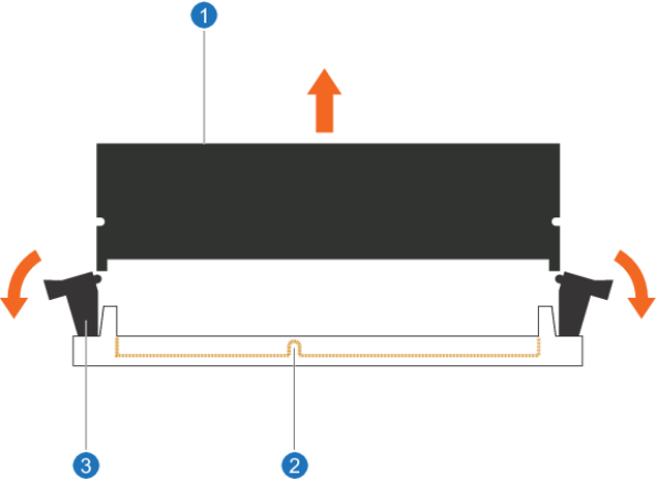
Figure 7: Removing a Memory Blank
2. Memory module socket
3. Memory module socket ejector/tab (2)
Review the following before removing or installing memory modules and memory module blanks.
WARNING: The memory modules are hot to touch for some time after the server has been powered down. Allow the memory modules to cool before handling them. Handle the memory modules by the card edges and avoid touching the components or metallic contacts on the memory module.
Caution: To ensure proper server cooling, memory module blanks must be installed in any memory socket that is not occupied. Remove memory-module blanks only if you intend to install memory modules in those sockets.
Caution: To prevent damage to the memory module or the memory-module socket during installation, do not bend or flex the memory module. In addition, do not apply pressure at the center of the memory module. Apply pressure at both ends of the memory module evenly, and make sure to insert both ends of the memory module simultaneously.
Use one of the following scenarios, based on your specific memory upgrade.
Use one of the following scenarios, based on your specific memory upgrade. For dual-server (HA) systems only, apply the memory kits as described below for BOTH server nodes.
Caution: Ensure that you fully-seat all memory DIMMs in their sockets. If DIMMs are not seated correctly, you could have unexpected errors and your memory count might not be correct after booting the server.
|
Current RAM |
RAM Kit(s) to Install |
What To Do |
|---|---|---|
| 64 GB (8 x 8 GB DIMMs) |
64 GB (8 x 8 GB DIMMs) |
|
|
Current RAM |
RAM Kit(s) to Install |
What To Do |
|---|---|---|
| 128 GB (16 x 8 GB DIMMs) |
64 GB (8 x 8 GB DIMMs) |
|
|
Current RAM |
RAM Kit(s) to Install |
What To Do |
|---|---|---|
| 64 GB (8 x 8 GB DIMMs) |
128 GB (8 x 16 GB DIMMs) |
|
|
Current RAM |
RAM Kit(s) to Install |
What To Do |
|---|---|---|
| 128 GB (16 x 8 GB DIMMs) |
128 GB (8 x 16 GB DIMMs) |
|
|
Current RAM |
RAM Kit(s) to Install |
What To Do |
|---|---|---|
|
64 GB (8 x 8 GB DIMMs) |
256 GB (16 x 16 GB DIMMs) |
|
|
Current RAM |
RAM Kit(s) to Install |
What To Do |
|---|---|---|
|
64 GB (8 x 8 GB DIMMs) |
256 GB (8 x 32 GB DIMMs) |
Caution: To ensure proper system cooling, memory module blanks must be installed in any memory socket that is not occupied. Remove memory module blanks or modules only if you intend to install memory modules or blanks in those sockets. |
|
Current RAM |
RAM Kit(s) to Install |
What To Do |
|---|---|---|
| 64 GB (8 x 8 GB DIMMs) |
256 GB (16 x 16 GB DIMMs) |
|
|
Current RAM |
RAM Kit(s) to Install |
What To Do |
|---|---|---|
|
64 GB (8 x 8 GB DIMMs) |
384 GB (24 x 16 GB DIMMs) |
|
|
Current RAM |
RAM Kit(s) to Install |
What To Do |
|---|---|---|
|
128 GB (16 x 8 GB DIMMs) |
256 GB (8 x 32 GB DIMMs) |
|
|
Current RAM |
RAM Kit(s) to Install |
What To Do |
|---|---|---|
|
64 GB (8 x 8 GB DIMMs) |
128 GB (8 x 16 GB DIMMs) AND 256 GB
|
|
|
Current RAM |
RAM Kit(s) to Install |
What To Do |
|---|---|---|
|
64 GB (8 x 8 GB DIMMs) |
256 GB (16 x 16 GB DIMMs) AND 256 GB
|
|
|
Current RAM |
RAM Kit(s) to Install |
What To Do |
|---|---|---|
|
64 GB (8 x 8 GB DIMMs) |
64 GB (8 x 8 GB DIMMs) AND 512 GB
|
|
|
Current RAM |
RAM Kit(s) to Install |
What To Do |
|---|---|---|
|
64 GB (8 x 8 GB DIMMs) |
128 GB (8 x 16 GB DIMMs) AND 512 GB
|
|
|
Current RAM |
RAM Kit(s) to Install |
What To Do |
|---|---|---|
|
64 GB (8 x 8 GB DIMMs) |
768 GB
|
|
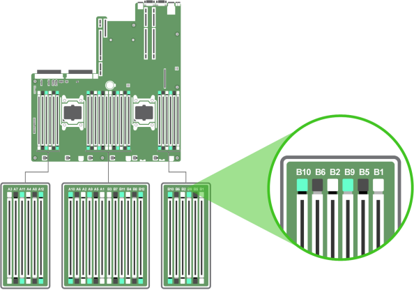
The following diagram shows the memory sockets available in the Xcellis Workflow Director, Artico (R630) and Xcellis Workflow Extender (R630) systems.
Figure 8: Memory Sockets (Left Side of Motherboard)
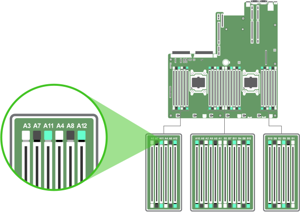
Figure 9: Memory Sockets (Center of Motherboard)
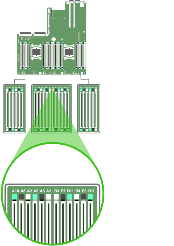
Figure 10: Memory Sockets (Right Side of Motherboard)
Note: The following applies to both memory modules and memory module blanks.
- Locate the appropriate memory module socket.
- Release the memory module or blank from the socket by simultaneously pressing the ejectors on both ends of the memory module socket.
Figure 11: Removing a Memory Module
Figure 12: Removing a Memory Blank
2. Memory module socket
3. Memory module socket ejector/tab (2)
Note: The following applies to both memory modules and memory module blanks.
- Locate the appropriate memory module socket.
- If a memory module needs to be replaced, or a memory module blank is installed in the socket, remove it.
Retain the removed memory module blank(s) for future use.
- Align the edge connector of the memory module with the alignment key of the memory module socket, and insert the memory module in the socket.
Note: The alignment key keeps you from incorrectly install the memory module in the socket.
- Press the memory module with your thumbs until the socket levers firmly click into place.
When the memory module is properly seated in the socket, the levers on the memory module align with the levers on the other sockets with memory modules installed.
Figure 13: Installing a Memory Module
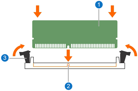
2. Alignment key
3. Memory module socket ejector (2)
Figure 14: Install the Cooling Shroud
|
1. Cooling shroud |
Replace the cooling shroud, as indicated in the image above.
- Align the slots on the server cover with the tabs on the chassis.
- Press the cover release latch, and push the cover toward the front of the chassis until the latch locks into place.
- Turn the latch release lock clockwise to the locked position.
Figure 15: Install the Server Cover
|
1. Latch release lock |
|
2. Server cover |
|
3. Latch |
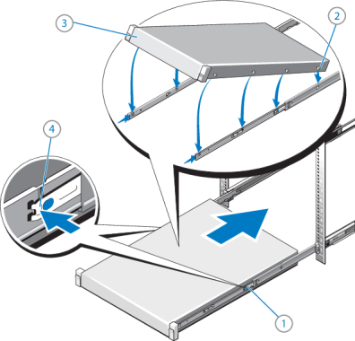
Install the server in a rack as follows:
- Place the MDC Node into the rail J-slots.
- Push the rail levers in on both sides of the server, and slide the server into the rack until it clicks into place.
- If needed, install a hard-mount screw under each latch with a #2 PHILLIPS® screwdriver to secure the server Node to the front of the rack.
- Unless this will be done later, connect Ethernet, Fibre Channel and power cables to the back of the server Node. Use the labels applied earlier to identify where these cables should be connected.
WARNING: Because the chassis weighs 33.08 lbs (15.01 kg), two people are required to lift it.
Figure 16: Installing the Server in a Rack
- Attach the right end of the bezel onto the server node.
- Attach the left side of the bezel onto the system. You should hear an audible "click" when it is installed correctly.
Figure 17: Install the Front Bezel
Note: Do not attach peripherals at this time if continuing the R630 installation procedure. Use the labels created earlier in the procedure to assist with attaching these cables.
- Attach peripheral cables.
Note: Do not attach power cables at this time if continuing the R630 installation procedure.
- Attach power cables.
Note: Do not power on the Xcellis Workflow Director server node at this time if continuing the installation procedure.
Do the following to power on a single node:
- Push the power switch on the front of the node you wish to power on.
- If you want this node to operate as the primary node perform a failover ( see ) after the system is powered up.
- Mount the file systems on all LAN and SAN clients.
- Restart I/O access to all LAN clients.
- If NAS Failover for NFS Clusters (NFS-HA) was previously enabled, click here to re-enable NFS-HA.
Note: You do not need to perform the server fail-over operation at this time if continuing the installation procedure.
Access the command line of the node currently operating as primary, and initiate the graceful fail-over to the server node currently acting as secondary:
- Open an SSH connection to the appropriate server and use the IP address assigned to the node on the Management or LAN Client network, or use the Service Port IP address, if connected to the Service Port.
Service Port IP addresses (if used):
Note:
Node 2
- Log in to the server node with the following credentials:
- User name:
stornext - Password:
<stornext user accountpassword>Note:
passwordis the default password for the stornext user account. If the password has been changed, use the current password.
- User name:
- Enter
sudo rootshto gain root user access. - Enter the password for the
stornextuser account again.
- Confirm that the server node you are connected to is operating as the primary. Enter:
- Verify the output is (bold text used for clarification):
- On the node operating as the primary, initiate an HA fail-over to the node operating as the secondary.
- Verify the node has failed over. Enter:
- Verify the output is (bold text used for clarification):
snhamgr -m status
:default:primary:default:running:
This indicates the node you are connected to is running, and is set as "primary", and that the secondary node is currently "running".
Note: If you have NFS-HA enabled, click here for the instructions to stop NAS prior to using this command.
For CentOS7-based systems (, , , and systems), enter:
systemctl stop cvfs
Note: The systemctl stop cvfs command does not provide any command-line status feedback on the progress of stopping cvfs operations. You will need to be patient and wait until you again have access to the command line prompt.
Wait until the secondary node becomes the primary. (Time may vary.)
snhamgr -m status
:default:stopped:default:primary:
This indicates that the node you are connected to has "stopped" as primary, and that the node previously operating as secondary is now operating as "primary". If this is not what is shown, wait and enter the snhamgr -m status command again.
You can leave the SSH connection to this server node running if you will access this server again soon.
-
Press <F2> to enter System Setup, and check the System Memory setting.
The server should have already changed the value to reflect the installed memory. If the value is incorrect, one or more of the memory modules may not be installed properly. Ensure that the memory module is firmly seated in the memory module socket.
- Run the System Memory Test in System Diagnostics.
Install the Memory in the Other Server Node
For dual-server (HA) systems only, repeat this entire procedure for the other server.
Continue to Install the Server Top Cover >>
* Back to Checklist: Server Installation *
* Back to Xcellis Foundation Hardware Installation Overview and Checklist (for systems). *