|
|
Install Drives Into the QXS-456 Drive Chassis |

The following applies to systems.
The 4U56 chassis — RAID chassis and / or expansion chassis — are shipped pre-assembled with pre-installed drawers. You must manually install the drives into the drawers.
To install drives into a 4U56 chassis, you must first open the drawer to access the drive bays. The chassis uses a sledded drive positioned to stand on end, allowing for insertion into the drawer. Each LFF drive is mated to its connector on the drawer PCBA.
Important Considerations
- You must populate the 4U56 chassis with a minimum of 14 drives.
- Install 7 drives in drawer 0, slots 0-6.
- Install 7 drives in drawer 1, slots 28-34.
- Distribute additional drives between the two drawers to mitigate potential performance bottlenecks.
-
Due to weight and / or lifting constraints, ensure the 4U56 chassis is installed within the applicable rack before populating the chassis with drives.
- Before the initial installation of drives, ensure that the rack is stabilized — that the leveling screws down and locked. This stabilization will prevent the possibility of the rack tipping over when populating the QXS-456.
- If you are going to fully populate the entire drawer(s), install the drives starting from the back row and moving towards the front row. Make sure to provide adequate support for the weight of the extended drawer as you install the drives.
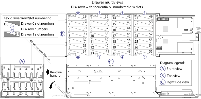
Diagram 1: Drive Locations
|
The above image illustrates the location of the drives and drive numbers (0-55). Drawer 0 contains drives 0-27. Drawer 1 contains drives 28-55. Populate the drawer from the front to the back with drives (0-27 for Drawer 0 and 28-55 for Drawer 1). |
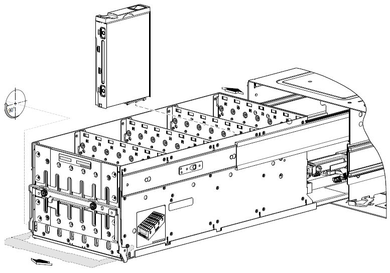
Diagram 2: Installing Drives
|
The above image illustrates the installation of drives into a drawer. When orienting the drive module for insertion into the target drawer, note the following: The drive installation procedure applies to the left drawer (Drawer 0) and the right drawer (Drawer 1). Drive row and slot numbering for each drawer is provided on the sticker laminated to the exterior wall of each drawer. |
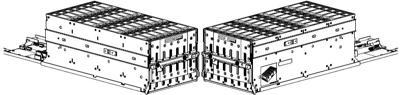
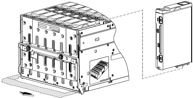
Diagram 3: Drawer 0 Fully Populated
|
The above image illustrates Drawer 0 fully populated with drives. Note the following: Staggered elevation of slide rails Locations of laminated drawer row/slot-numbering reference diagrams Orientation of installed drives |
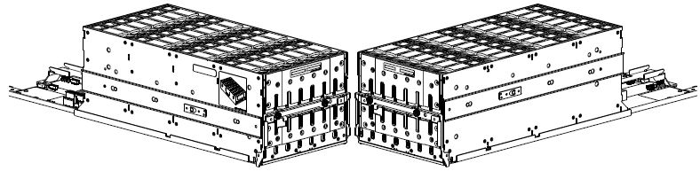
Diagram 4: Drawer 1 Fully Populated
|
The above image illustrates Drawer 1 fully populated with drives. Note the following: Staggered elevation of slide rails Locations of laminated drawer row/slot-numbering reference diagrams Orientation of installed drives |
Caution: Before opening and/or accessing either of the drawers via its handle, you must first remove the front bezel. The chassis bezel is required to provide EMI protection for the product, you must re-attach the bezel to the chassis after examining the drawer.
- Using a No.2 phillips screwdriver, loosen the two screws securing the handle to the front face of the drawer.
- Turn the thumbwheel counter-clockwise to disengage the handle from it’s upright stowed position.
Figure 1: QXS-456 with bezel removed
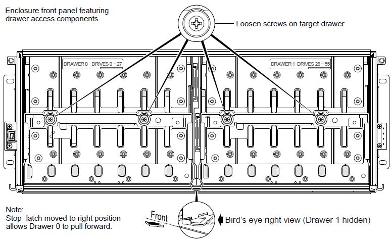
- Move the drawer stop-latch so that the target drawer can travel along the slide.
- Move the stop-latch to the right to open Drawer 0 (left drawer).
- Move the stop-latch to the left to open Drawer 1 (right drawer).
- Revolve the drawer handle downwards by 90° so that the drawer can be pulled outward for viewing drive slots.
Figure 2: QXS-456 opening drawer
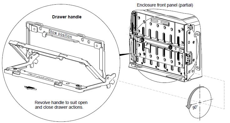
The drawer handle is in the pull and stow positions.
- Face the front of the drawer, and using the handle, pull the drawer outward along the drawer slide until it meets the drawer stop.
Make sure that there are not any loose cable wires protruding beyond the limits of the chain-flex cable.
- With the drive module standing on end, and the LEDs oriented to the left, insert the drive module into the vertically-aligned drive slot to seat it into the connector on the drawer PCBA.
- Verify that you have inserted the drive module into the slot as far as it will go, to ensure that the module if firmly seated in the drawer PCBA
- Slide the drawer into the chassis along the drawer slide until it properly seats in the drawer bay.
- Verify that there are not any loose cable wires protruding beyond the limits of the chain-flex cable.
- Revolve the handle upwards such that it is flush with the drawer front panel in the stowed position.
- Using a No. 2 Phillips screwdriver, tighten the two screws securing the handle to the front face of the drawer.
- Re-attach the bezel to the front of the chassis.
Continue to Install the QXS SFPs >>
* Back to Checklist: QXS Chassis Installation *
* Back to Xcellis Foundation Hardware Installation Overview and Checklist (for systems). *
*Back to Hardware Installation Overview and Checklist *