|
|
Install the 12-Drive and 24-Drive Chassis Rails |

To install rack rails for the 12-drive and 24-drive chassis, you will need to complete the following steps.
Installation Steps
- Review all prerequisites. See Install the QXS Chassis.
- Attach the side brackets to the rear mounting holes on each side of the chassis.
- If you are installing the chassis into square or round-hole racks, you need to install hanger fasteners in the front and rear rail components.
Proceed to Step 3: Install the Rails if either or the following are true:
- Hanger fasteners are pre-installed in rail sets.
- You are installing the chassis into a rack with pre-tapped holes.
- Install the rails for the 12 and 24-drive chassis. Keep in mind that the rail kit supports both the controller and expansion chassis.
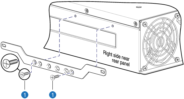
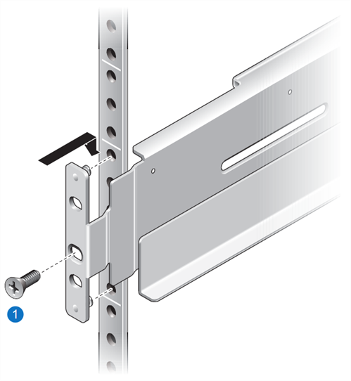
- Use 2 #8-32 x 3/16 flathead Phillips screws to attach a side bracket to the rear mounting holes on one side of the chassis.
- Repeat step 1 to attach the other bracket to the other side of the chassis.
Figure 1: Attaching bracket to a 12-
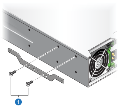
1. Screws (2 per bracket) Figure 2: Attaching bracket to 24-depth enclosure (standard-depth)
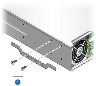
1. Screws (2 per bracket) Figure 3: Attaching bracket to 24-drive enclosure (reduced-depth)
1. Screws (2 per bracket)
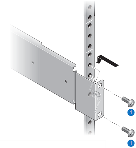
- Install the hanger fasteners in the front rail components with the heads facing inward.
Front rail sleeves require two pins each.
- Install the hanger fasteners in the rear rail components with the heads facing inward.
Rear rail inserts require one pin each.
Keep in mind that you can loosely attach the fasteners to the hold the rails in place, and then position the rails vertically and horizontally for accurate alignment. As soon as you have an accurate alignment, tighten the fasteners.
Figure 4: Pre-Installed Hanger Fasteners
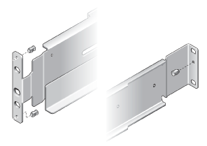
- Slide the rear rail insert into the front rail sleeve.
Figure 5: Rail components
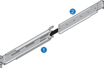
1. Front rail sleeve 2. Rear rail insert
- Determine the chassis depth required by the rails.
- Fit the rail assembly to the rack and note the tapped holes in the rear rails that align with the slotted holes in the front rails.
- If cage nuts are pre-installed, remove them from the locations where hanger screws are inserted.
- Select two or three #8-32 x 3/8 flathead Phillips screws, depending on your chassis depth, to loosely attach the rear rail to the front rail.
You will tighten the screws later.
Figure 6: Assembled adjustable-length rail
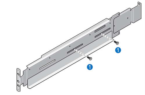
1. Screws: Code B - P/N:01-00000262-00-01 - Do one of the following depending on the type of holes in the rail:
 Square-hole racks
Install cage nuts in the front and rear rack holes, where the rails will be attached.
If you insert the cage nuts incorrectly, use a Cage Nut Removal Tool to more easily remove the nuts from the rack holes.
Round-hole racksInstall clip nuts in the front and rear rack holes, where the rails will be attached.
- Position the rail's front and back mounting flanges so that the through-holes align with the corresponding rack holes, and note the location of the alignment.
Hint
Align the bottom of the rail with the bottom of the rack unit where you would like to install the rails. Rails should not be installed where the rail will straddle rack units (U). Most racks provide alignment markers indicating the rack units used for rail installation.
- Attach three fasteners at the front of the rack and two fasteners at the rear of the rack, as shown by the red X marks in the following installation detail views.
On the following diagram, keep in mind that elevation numbers are arbitrary — they simply represent vertical location within the rack. Blue indicates where a 2U chassis would be positioned relative to the cage nuts. 1U rack heights are shown next to cage nut installation locations.
Figure 7: Cage nut placement
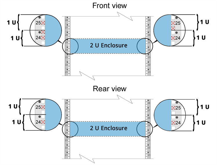
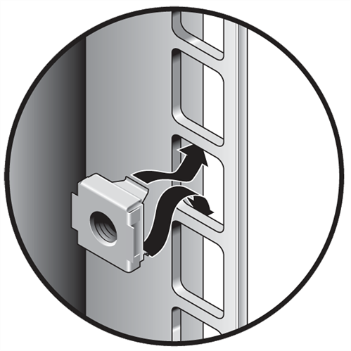
Figure 8: Cage nut installation
- If your rack does not have pre-tapped holes, do the following:
- Remove any cage nuts from the holes.
- Hook the front and rear hanging pins into the rack’s holes.
- Use one of the following, as appropriate, to attach the front of the rail assembly to the front of the rack:
- 1 #10-32 x 5/8 flathead Phillps screw
- Appropriate 5 or 6 mm flathead Phillips screw
In a rack with pre-tapped holes, push the rails outward to maximize the opening width while tightening the screws.
Figure 9: Attaching front rail assembly
1. Screw: Code D - P/N:01-00000265-00-01 or 01-00000266-00-01 or 01-00000268-00-01
- Use one of the following, as appropriate, to attach the f rear of the rail assembly to the rear of the rack:
- 2 #10-32 x 3/4 truss Phillips screws
- Appropriate 5 or 6 mm panhead screws
In a rack with pre-tapped holes, push the rails outward to maximize the opening width while tightening the screws.
Figure 10: Attaching rear rail assembly
1. Screw: Code C - P/N:01-00000264-00-01 or 01-00000267-00-01 or 01-00000269-00-01
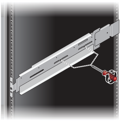
- Tighten the screws that you loosely attached in Step 3.
Figure 11: Tightening rail screws
- Repeat steps 1, 2, and 3 for the other side of the chassis.
Continue to Install the QXS Chassis >>
* Back to Checklist: QXS Chassis Installation *
* Back to Xcellis Foundation Hardware Installation Overview and Checklist (for systems). *
*Back to Hardware Installation Overview and Checklist *