|
|
Install the Expansion Cards |

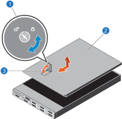
- Turn the latch release lock to the unlock position.
- Lift the cover release latch and remove the server cover.
Figure 1: Server Cover Removal
|
|||
|
|||
|
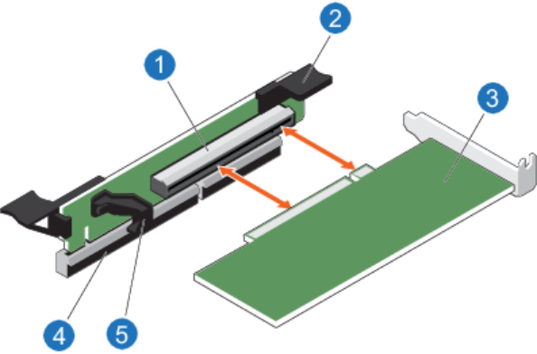
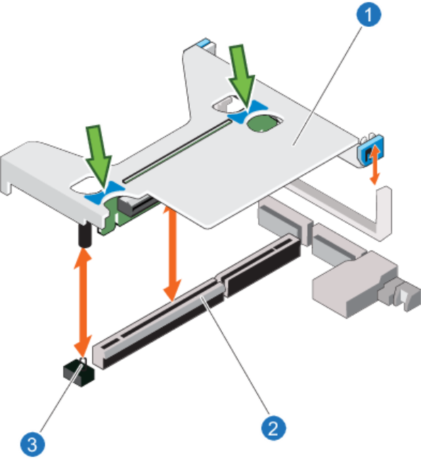
- Holding the 2 blue touch points located on the bracket, lift the expansion card riser from the riser connector located on the system board.
- Remove the card from the riser.
Even though you will not populate cards in Expansion Card Riser 1 until later, remove the card now in order to have the space needed to install a card in Expansion Card Riser 3.
Figure 2: Expansion Card Riser 1

|
|||
|
|||
|
Note: Due to clearance issues with the Fibre Channel Cards, you must install the Fibre Channel cards in Slot 3 prior to installing the Expansion Cards for Slots 1 and 2.
- Unpack the expansion card and prepare it for installation.
- Locate the expansion card connector on Expansion Card Riser 3.
- Remove the slot filler bracket, if needed.
- Holding the card by its edges, position the card so that the card edge connector aligns with the expansion card connector, and the rear of the expansion card is aligned with the small horizontal slot in the black plastic expansion card support / alignment tab.
- Rotate the card as necessary to push the ports out the back of server slot 3.
- Seat the card into the riser card slot.
-
Align the expansion card riser with the connector and the riser guide pin located on the system board.
- Lower the expansion card riser into place until the expansion card riser connector is fully seated in the connector.
- Insert SFPs. (Remember to install SFPs so that the PCB is facing upwards.)
- Do not attach the Fibre Channel cables yet. You will attach the Fibre Channel cables with guidance from the StorNext Connect Install App.
- If your configuration uses 16 GB FC or 32 GB FC cards, install the required SFP+ transceivers into the correct FC ports prior to connecting the FC cables.
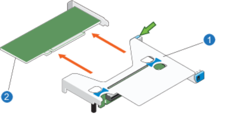
Note: If expansion card ports extend off the back of the expansion card, such as for FC ports, gently install the card, as follows:
Do not remove Expansion Card Riser 3 from the motherboard prior to installing the Slot 3 Expansion Card. If you do, you will be unable to reinstall Expansion Card Riser 3 due to the FC ports that extend off the port end of the card.
Additional Notes
Figure 3: Expansion Card in Slot 3
|
|||
|
|||
|
|||
|
|||
|
Note: Use this procedure only if an expansion card was pre-installed in slot 2, and you need to install an expansion card in slot 1.
- Disconnect any cables connected to the expansion cards.
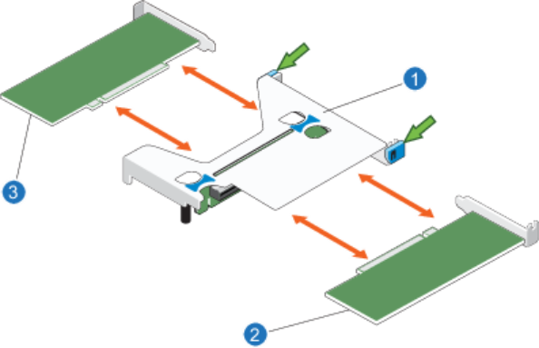
- Rotate one of the two blue tabs for the expansion card being removed (indicated by the two green arrows below).
- Grasp the expansion card or slot filler brackets for the slot used for the expansion card, if installed by its edges and remove it from the connector on expansion card riser 1.
Note: If you are removing the card permanently, you must install a slot filler brackets over empty expansion slots to maintain Federal Communications Commission (FCC) certification of the system. The brackets also keep dust and dirt out of the system and aid in proper cooling and airflow inside the system.
Figure 4: Remove Expansion Card for Slot 2 from Expansion Card Riser 1 (looking toward the back of the server)
|
|
Note: You must install the expansion card in slot 1 before installing the expansion card in slot 2. If you install the expansion card in slot 2 first, you will be unable to install the expansion card in slot 1.
- Unpack the expansion card(s) and prepare it for installation.
- Open the blue sliding tab, and remove the blue hinged card retainer on the Slot 1 or Slot 2 side of the bracket.
- Holding the expansion card by its edges, position the card so that the card edge connector aligns with the expansion card connector.
Note: If installing cards in both slot 1 and slot 2, install the expansion card in slot 1 first, followed by the expansion card in slot 2.
- Insert the card edge connector firmly into the expansion card connector until the card is fully seated.
- Replace the blue hinged card retainer back into its original position, making sure that it is pushed securely into Expansion Card Riser 1.
Note: Install slot brackets in empty expansion slots to maintain Federal Communications Commission (FCC) certification of the system. The brackets also keep dust and dirt out of the system and aid in proper cooling and airflow inside the system.
- Rotate one of the two blue tabs for the expansion card being installed (indicated by the two green arrows below.
-
Note: If this tab is not moved back into place, the riser card cannot be installed into the server node.
- If slot blockers were used, replace them all.
- If you removed SFPs from the expansion card, put them back into the ports.
Additional Notes
- Do not attach the 10 Gbe network cables yet. You will attach these cables with guidance from the StorNext Connect Install App.
- If your configuration uses 10 GbE or 10 GbE Base-T cards, install the required SFP+ transceivers into the network ports of both server nodes prior to connecting the network cables.
Figure 5: Remove Expansion Cards from Expansion Card Riser 1 (Looking toward the back of the server)
|
|||
|
|||
|
- Push the card retention tab on the side of the Slot 1 expansion card inward.
You cannot install the card into the Expansion Card Riser 1 slot on the system board unless this tab is pushed in.
- Align the expansion card riser with the connector and the riser guide pin located on the system board.
- Lower the expansion card riser into place until the expansion card riser connector is fully seated in the connector.
- Using the 2 blue touch point locations on the top of Expansion Card Riser 1, push Expansion Card Riser 1 back into position.
Figure 6: Expansion Card Riser 1
|
|||
|
|||
|
Review the information about Expansion Cards – Logical Port Numbers and Slots >>
OR
Continue to Install the Server Memory >>
* Back to Checklist: Server Installation *
* Back to Xcellis Foundation Hardware Installation Overview and Checklist (for systems). *
*Return to Hardware Installation Overview and Checklist *