|
How to Create a PDF |
VS2124 Installation
Step 1: Choose a Location
When choosing an installation site for the VS2124, make sure the location meets the requirements of VS2124 Site Planning, which contains detailed physical and environmental requirements.
Step 2: Prepare for the Installation
VS2124 default network IP addressses and initial installation credentials are available at Access Default Login Credentials. In addition, you can print a copy of the blank Networking IP List to help you record your IP addresses. If you are installing multiple VS2124 systems, Quantum recommends that you record all IP address and login information.
Before you begin the installation procedure, make the preparations described in the following sections:
 Necessary Tools
The following tools are required for unpacking and installing the VS2124 system:
- #2 Phillips screwdriver
- Small flat head screwdriver
- Notebook computer or USB keyboard, USB mouse and VGA Monitor
Taking ESD Precautions
Some components within the VS2124 system contain static-sensitive parts. To avoid damaging these parts while performing installation procedures, always observe the following precautions:
- Keep the VS2124 system turned off during all installation procedures.
- Keep static-sensitive parts in their original shipping containers until ready for installation.
- Do not place static-sensitive parts on a metal surface. Place them inside their protective shipping bag or on an anti-static mat.
- Wear anti-static wrist bands when unpacking and handling the units, and avoid touching connectors and other components.
Note: Dry climates and cold-weather heating environments have lower relative humidity and are more likely to produce static electricity.
VS2124 Safety Information
Caution: Before installing or configuring the system, read the safety information.
Step 3: Unpack the VS2124
By following these unpacking instructions, you help ensure that the system will continue to be safeguarded after it arrives at the installation site. Your VS2124 is delivered ready to power-on and connect to your network infrastructure. The server and rail kit arrive in a single box, requiring a single shipping pallet.
Contents and Packaging
Your VS2124 server arrives in a box with the following items:
| Item | Description |
|---|---|
| VS2124 Quick Start Guide |
|
| Rack mount rails | |
| Cable Management Arm Kit |
Includes:
|
| Accessory Kit |
Includes:
|
Carefully unpack and remove the components from the packing materials.
Caution: Make sure to retain all packing materials, as well as the documentation and other items included in the shipping box. The packaging materials must be used if the system is relocated.
WARNING: The VS2124 weighs approximately 120 pounds. Either a server lift or a minimum of two people are required to lift the chassis.
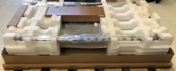
Node, Rail Kit, and Accessory Kit
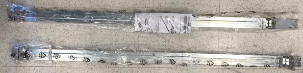
Rail Kit
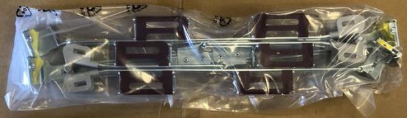
Cable Management Arm Kit
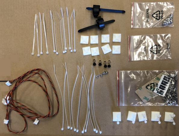
Accessory Kit
Step 4: Install the VS2124 System in the Rack
This section provides instructions on installing the VS2124 chassis into a rack unit with the quick-release rails provided.
Note: A rack is not included with the VS2124. See the Rack Requirements in VS2124 Site Planning for rack specifications.
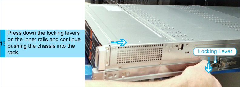
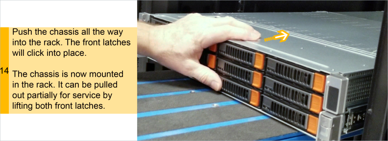
Procedure: Install the VS2124 System in the Rack
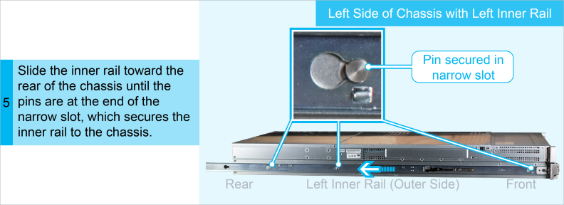
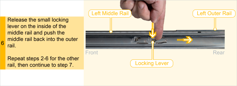
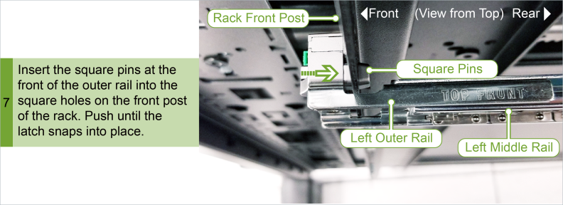
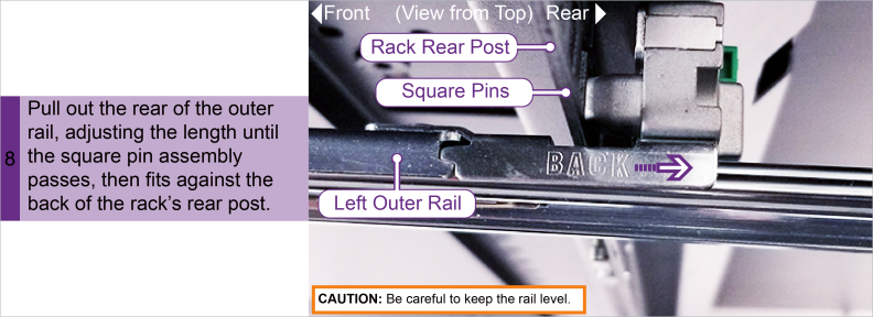
To help ensure that you correctly cable the system and to reduce the possibility of tipping over the rack, install your VS2124 as low in the rack as possible, leaving enough space in the rack for future system expansion.
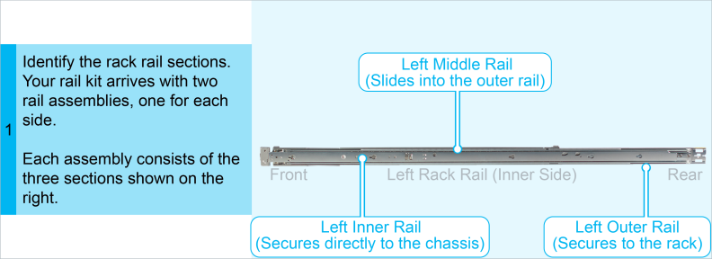
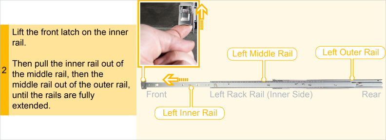
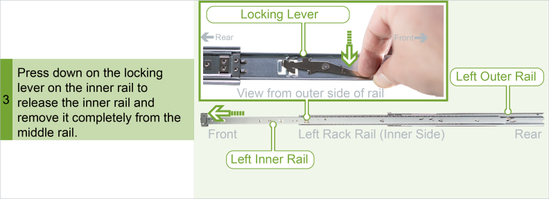
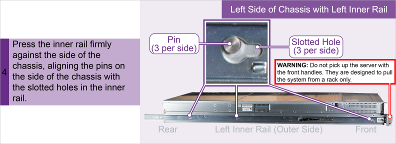
WARNING: Due to its weight and to prevent potential tip-over, Quantum recommends installing the server as low as possible in an empty rack.
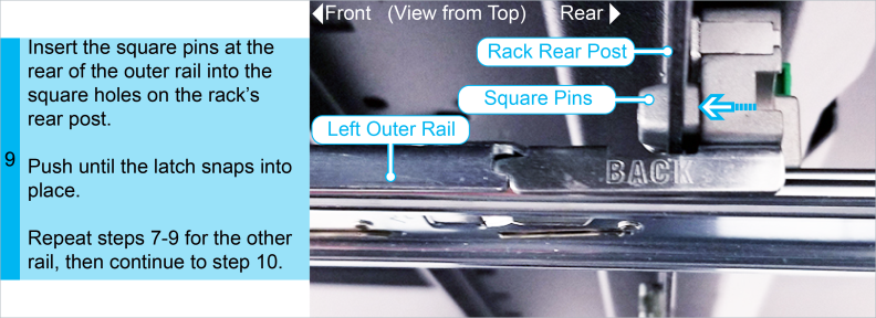
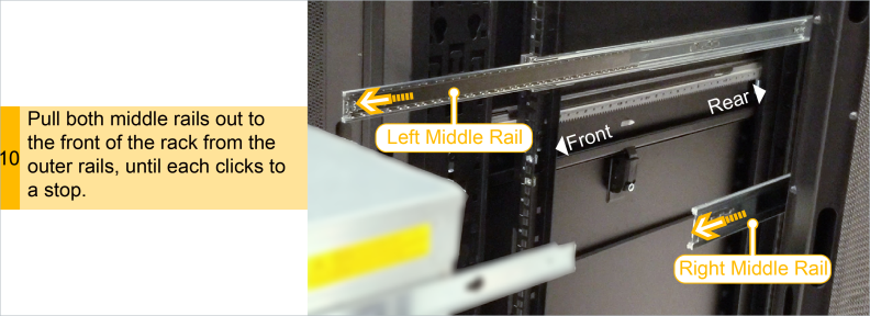
WARNING: The VS2124 weighs approximately 120 pounds. Either a server lift or a minimum of two people are required to lift the chassis.
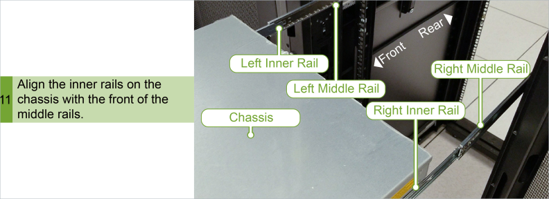
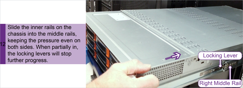
Step 5: Install the Cable Management Arm
Procedure: Installing the Cable Management Arm
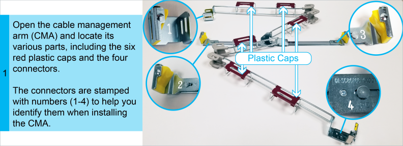
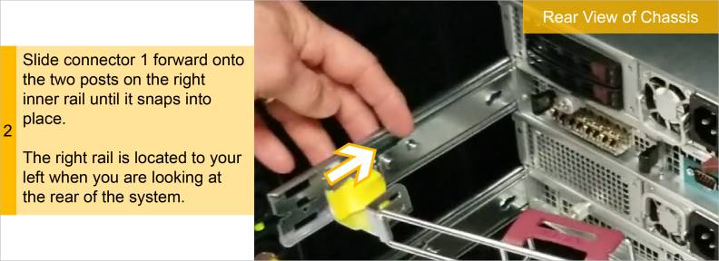
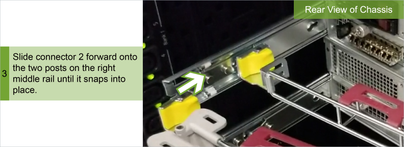
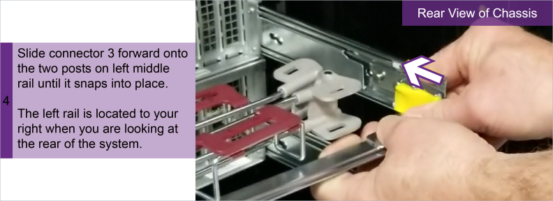
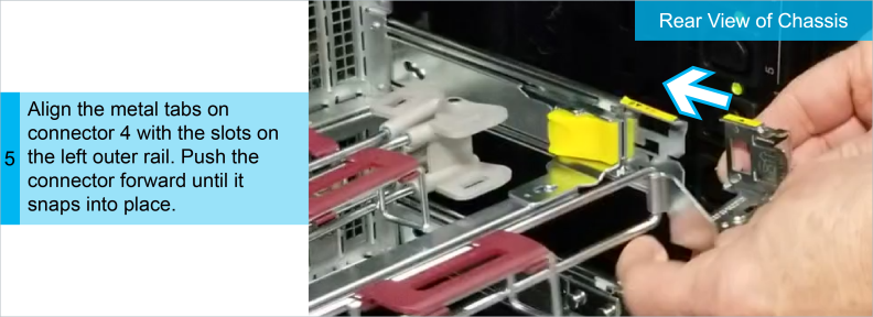
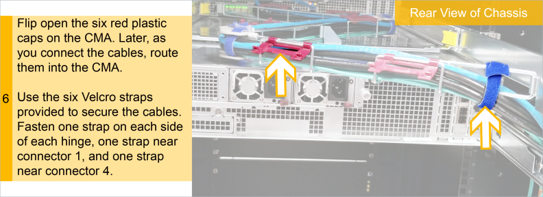
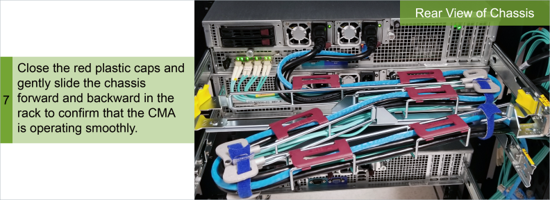
Your VS2124 uses a one-piece cable management arm (CMA) that can be serviced while the server is running. The CMA keeps the rear cables organized and clear of the rail mechanisms when the system is extended out from the rack. The CMA attaches to your VS2124 rails using four numbered connectors.
Step 6: Connect Power Cords and Power On
Step 6a: Connect System to Power and Management Laptop
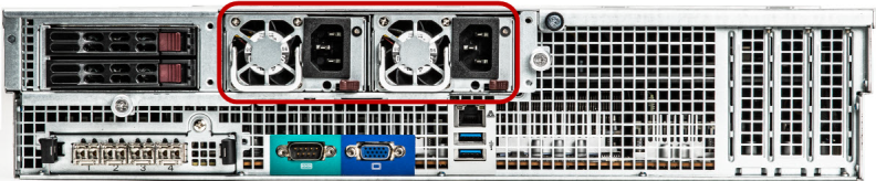
- Connect each power supply to a primary and secondary AC power source using the provided power cables. Use the attached straps to secure the power cords to the chassis.
- The power cord retaining clip can block full insertion of the power cord connector. Pull the clip forward before attempting to connect the power cord.
- Quantum recommends connecting each power cord to a separate AC circuit to ensure system availability in case of a power failure. Power supplies should be checked periodically for audible and LED warnings.
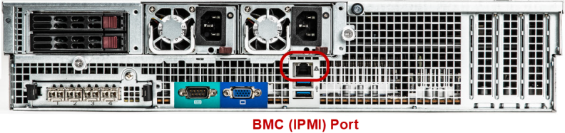
- To configure the management laptop's network settings to remotely connect to the server using the BMC (IPMI) interface, connect your laptop to the BMC (IPMI) port.
Additional Information
Additional Information
Check that all drives are correctly seated in all enclosures before powering on the node.
Caution: If you do not connect your management laptop to the BMC (IPMI) port at this point, the system may drop the default DHCP connection.
Step 6b: Power-on the VS2124
- To power-on the VS2124, press the Power button on the front of the Node.
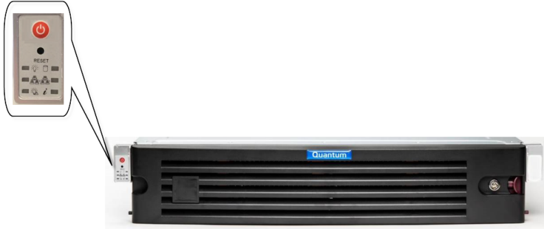
Note: After pressing the Power button, wait approximately 5 minutes for initial full power-up.
Step 7: Perform Initial Configuration
This section describes how to configure the network settings and enable the Windows Virtual Machine (VM) so you can access the network interfaces from outside the VS2124.
Note: This procedure assumes you are running Windows 7 on the computer. The steps might be different if you are using another operating system.
VS2124 default network IP addresses and initial installation credentials are available at Access Default Login Credentials. In addition, you can print a copy of the Networking IP List to help you record your IP addresses. If you are installing multiple VS2124 systems, Quantum recommends that you record all IP information.
Prerequisite: Connect and Configure Management Laptop
At this point in the procedure, the server is not connected to a network (LAN). All external-facing ports on the VM and host operating systems are set by default to DHCP. Use this section to connect to the Windows desktop to configure your network settings.
For Mac Laptops
- Select the Apple menu > System Preferences> Network, and select the Ethernet connection.
- In the Configure IPv4 drop-down list, select Manually.
- Enter the IP address and subnet mask values (leave gateway blank):
-
TCP/IPv4 address - 192.168.17.20
-
Subnet mask - 255.255.255.0
- Click Apply.
- Close the Network dialog.
- Wait at least two minutes for the laptop to enable the network connection.
For Windows Laptops
- Access the Network Connections control panel. To do this, press the Windows key on the keyboard, type
view network connectionsand press Enter. - Right-click on the network connection that corresponds to the Ethernet port on the computer (for example, Local Area Connection), and click Properties.
- Select Internet Protocol Version 4 (TCP/IPv4) in the list of connections, and then click Properties.
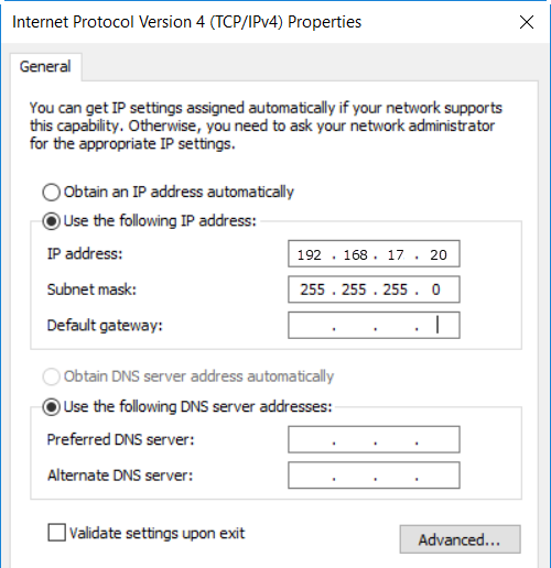
- The Internet Protocol Version 4 (TCP/IPv4) Properties window displays.
- Select Use the following IP address and then enter the following information:
- IP address - 192.168.17.20
- Subnet mask - 255.255.255.0
- Click OK, and then click Close.
- Wait at least two minutes for the computer to set the IP addresses on the local computer.
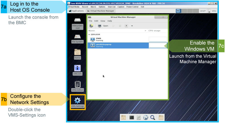 Step 7a: Login and Launch the Host Operating System (OS) Console
This section describes how to log into the BMC, launch the Host OS Console, and accept the EULA for the Virtual Machine Manager.
The easiest way to access the BMC is to configure the network settings on your laptop to use static network settings to create the direct, local link connection from the laptop to the VS2124 server. For details, refer to Prerequisite: Connect and Configure Management Laptop.
Note: The baseboard management controller (BMC) manages the interface between system-management software and platform hardware.
- In your browser, type the BMC IP address for the server, 192.168.17.21, in the address bar and press Enter.
-
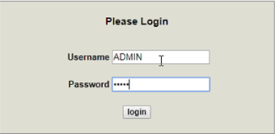
The login dialog appears.
Additional Information
- For web browsers, the VS2124 supports Firefox 26 or higher, Chrome 40 or higher, or Internet Explorer 11 or higher.
- If the Login window does not display, verify that you entered the correct IP address (192.168.17.21) and that the network settings on the computer are correct. Wait 10 minutes, then try again. If the Login window still does not display, contact Quantum Customer Support.
- Using the Default BMC information provided in Access Default Login Credentials:
- Type ADMIN for the Username.
- Type ADMIN once more for the Password and click login.
-
Note: If you want to change your BMC IP address, see Change the BMC IP Address (Optional).
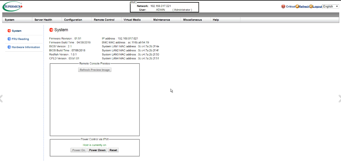
- Click on the Remote Control dropdown to change the left-side navigation to remote control options.
- Continue with the next section to use either an HTML5 or Java viewer to access the Windows VM console.
The Server home screen appears.
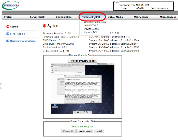
Access Windows VM using the HTML5 Viewer
Use these steps to access the BMC console using HTML-based viewer and controls.
- Select iKVM/HTML5 from the Remote Control dropdown.
- Click the iKVM/HTML5 button to access the Host OS.
- Check I read and accept the terms and click OK to close the EULA dialog.
- Click Close at the bottom of the dialog.
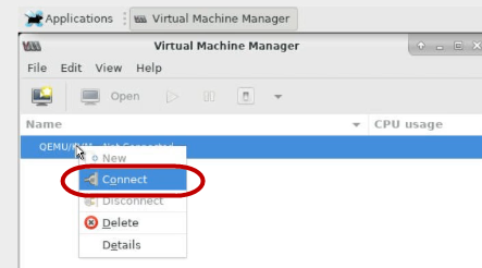
- In the Virtual Machine Manager window, right-click on <xxxx>/KVM and select Connect.
-
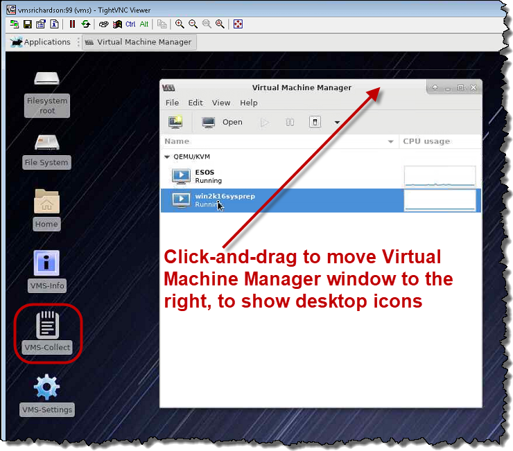
Click and drag the Virtual Machine Manager window to the right on the screen, to show the VMS-Settings icon.
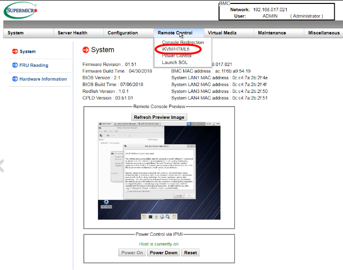
The iKVM/HTML5 screen appears.
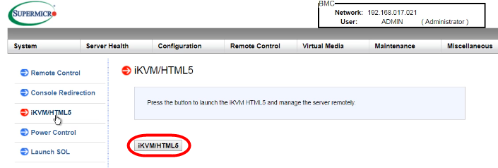
Note: At this point and only during initial installation, the Quantum End User License Agreement (EULA) appears.
For the HTML5 access method only, the Virtual Machine Manager screen appears with a message stating Unable to connect to <xxxx> system. Verify that the <xxxx> daemon is running.
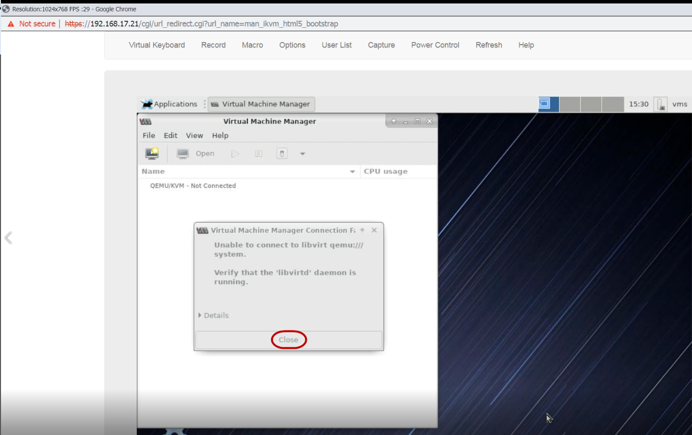
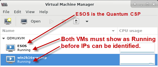
The VM is now connected and displays the Host OS Console, containing the ESOS (do not access or change) and win2k16sysprep VMs. Both VMs should have the status of Running below the VM name.
Access Windows VM using the Java Viewer
Use these steps to access the BMC console using the java-based viewer and controls.
Note: You must have Java version 8 or later installed to use this option.
- From the left-side navigation, click on Console Redirection, then click the Launch Console button.
- Click Keep to continue downloading, then click on the downloaded launch.jnlp file to launch it.
- Click Continue, then click Run on the Java viewer Do you want to run this application? dialog.
- Click and drag the Virtual Machine Manager window to the right on the screen, to show the VMS-Settings icon.
- Check I read and accept the terms and click OK to close the EULA dialog.
- Check the I read and accept the terms box and click OK.
A download confirmation message appears.
An Opening File message appears, then a Security Warning confirmation.
The Host OS Console displays.
Note: The desktop will show with the End-User License Agreement (EULA) window. The EULA only appears at first login.
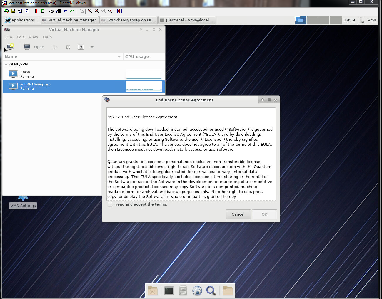
The VM is now connected and displays the Host OS Console, containing the ESOS (do not access or change) and win2k16sysprep VMs. Both VMs should have the status of Running below the VM name.
Step 7b: Configure Your Network Settings
This section describes how to configure your network settings.
Note: For setting the server's time zone, Network Time Protocol (NTP) is automatically set as part of this process.
Set IP Addresses
- Click and drag the Virtual Machine Manager window to the right, to show the VMS-Settings icon on the left side of the Host OS Console.
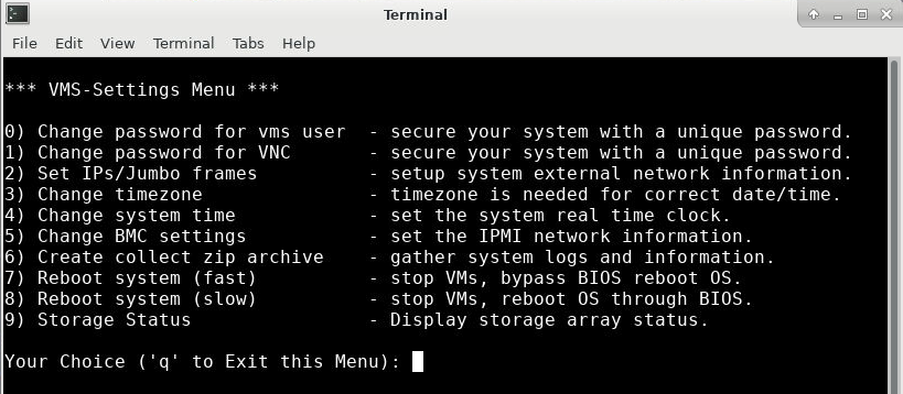
- Double-click the VMS-Settings icon to display the VMS-Settings Menu in a terminal (VNC console) window.
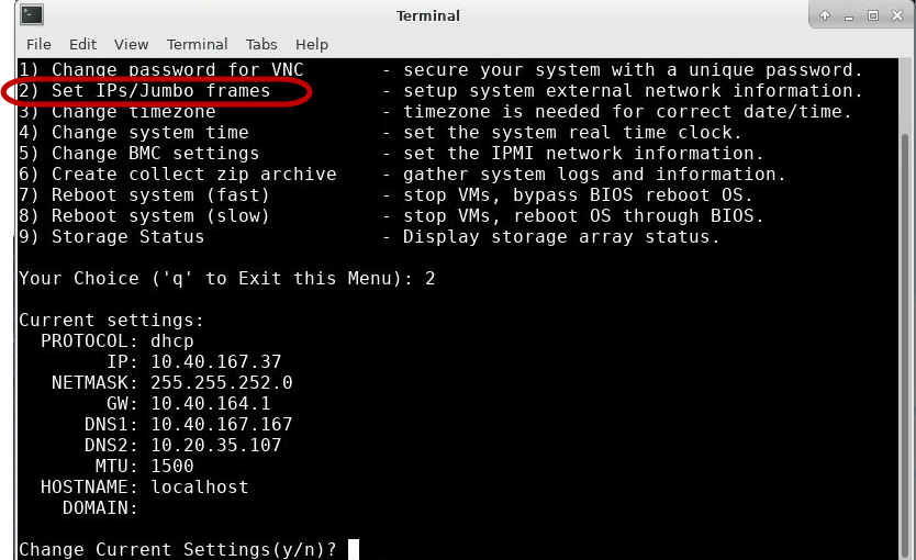
- In the VMS-Settings Menu, select option 2) Set IPs/Jumbo Frames and press Enter.
- Type y at the Change Current Settings (y/n)? prompt and press Enter.
- Press Enter at the Protocol 'manual' or 'dhcp'? [dhcp] prompt.
- Press Enter at each of the following prompts to use the default settings for:
-
IP address
-
Network Mask
-
Gateway
-
DNS1
-
DNS2
- If you are enabling jumbo frames, type y at the Enable Jumbo Frames? (y/n) prompt and press Enter.
- Select or change the default Hostname at the Hostname prompt.
- Type <your optional domain name> at the Domain prompt and press Enter.
- To apply all settings and restart the network connection, type y after Apply New Settings (y/n).
Note: What is VNC? Virtual Network Computing (VNC) is a remote control function for your server. A VNC Viewer (or client) is installed on the local (remote) computer and connects to the server, allowing the two to communicate and view/enable/adjust server settings from the computer. The server transmits its settings to the remote computer's viewer console.
VNC is an open-source interface using Remote Frame Buffer Protocol. Free clients are available for download. For example, Real VNC at https://www.realvnc.com.
The VMS-Settings menu appears. See Use the VS-Settings Menu for specifics on all VS-Settings Menu and submenu commands.
The current default settings are displayed.
Note: What are Jumbo Frames? A jumbo frame is an Ethernet frame with a payload greater than the maximum transmission unit (MTU) of 1,500 bytes. Jumbo frames are used on local area networks that support at least 1 Gbps and can be as large as 9,000 bytes, allowing an increase in the server's ingest capacity, thus increasing performance.
Caution: Before you choose to enable jumbo frames, you must have your network switch for the port enabled for jumbo frames. If not, communication issues between the server and destination will result.
The default setting is shown in brackets. Pressing Enter without an entry applies the default.
Note: You can change these settings per your company's standards/preferences as needed. Contact your network administrator for details.
Set the System Timezone
Complete the steps in this section to set your VS2124 to the local timezone for accurate status and reporting.
- From the VMS-Settings Menu, select option 3) Change timezone and press Enter.
- Continue using the menu options to set the system to your local timezone and press y to confirm.
- Enter q to exit the menu.
See Use the VS-Settings Menu for specifics on this menu option.
Note: Setting local time using option 4 is optional and typically not needed after the timezone has been set using option 3, since NTP services are already set.
Step 7c: Enable the Windows VM
This section describes how to enable the Windows VM so you can access the network interfaces from outside the VS2124.
- In the Virtual Machine Manager window, double-click on the Windows VM to open the Windows console.
- Switch to fullscreen view by clicking on the icon in the top-right corner.
- Click Next to continue.
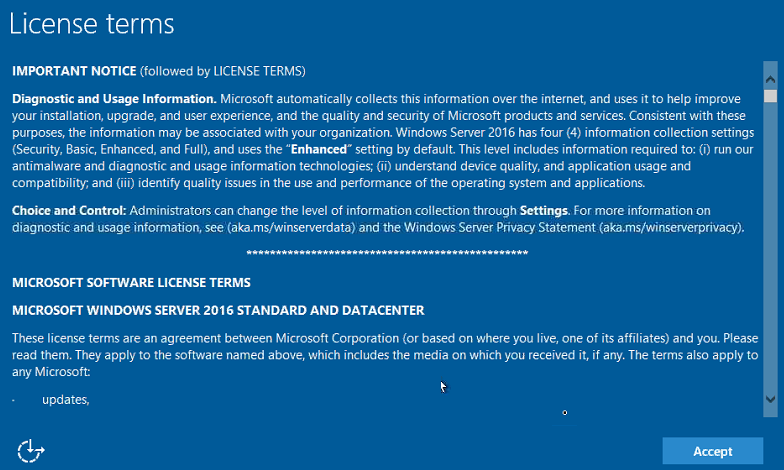
- Click Accept to continue.
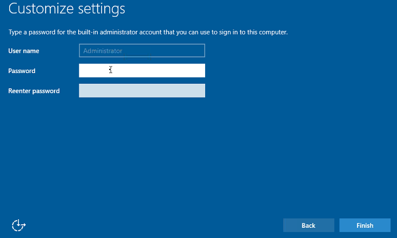
- Enter and reenter the new Windows Account Administrator password, then click Finish to complete your account setup.
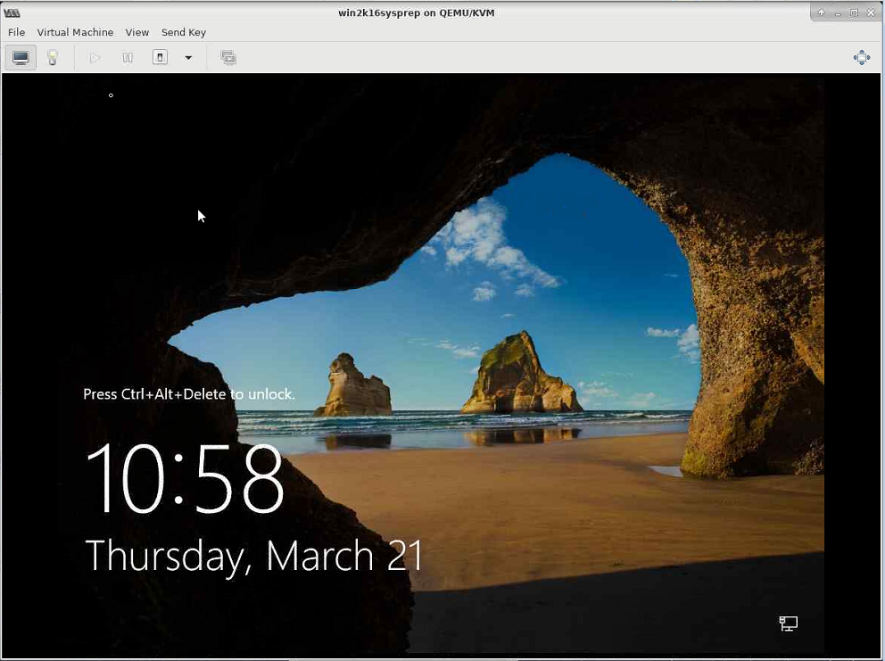
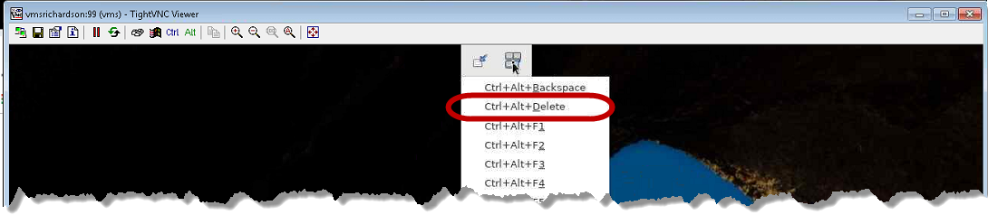
- To log on to the Windows Console as Administrator, move your mouse to the top-middle on the screen to show the dropdown controls.
- Select the Send key combination icon and select Ctrl-Alt-Delete.
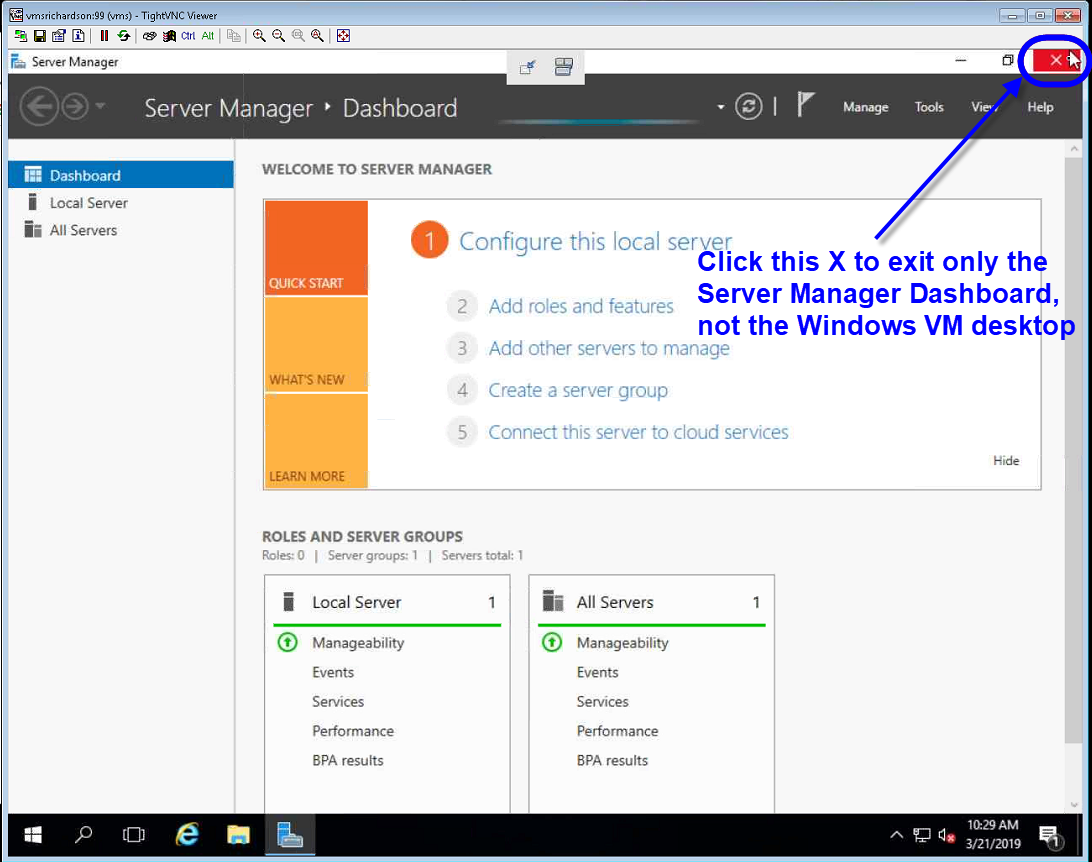
- To close only the Server Manager window (which is not used for the installation), click the X in the top-right corner of the Server Manager window (not the Windows Desktop window).
Note: You may need to move your mouse to activate the VM screen and view the icon.
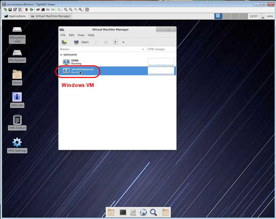
Note: Your screen controls may vary.

Note: To return from fullscreen view and access the Host OS Console, move your mouse to the top-center of the screen until a control appears (next image following) which allows you to leave fullscreen view. If using the BMC Java console, you may need to hold down the Shift key and left-click in the top-center of the screen until the control appears.

Note: At your first Windows login, you will see the following Windows startup screens:
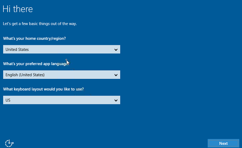
The Windows EULA appears.
The Customize Settings screen appears, where you set your Windows Account Administrator password for the VS2124. The username is Administrator.
Note: Be sure to separately note your new Windows Account Administrator password.
After a VMS Initialization - Customizing network port names confirmation appears briefly on the first login, the Windows lock screen is displayed.
Note: You may need to press and hold Shift, move your mouse to the top-middle of the window, left-click and release both keys at once to show the dropdown controls.
Also: Also, pressing the Ctrl-Alt-Del key combination on your keyboard does not work in the Windows VM screen. Your screen sizing controls may vary.
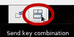
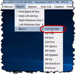
Note: Depending on your Windows VM screen configuration, you can also display the Windows desktop by selecting Macro > Macro > Ctrl-Alt-Del from the toolbar.
The Windows desktop is displayed and the Server Manager automatically opens.
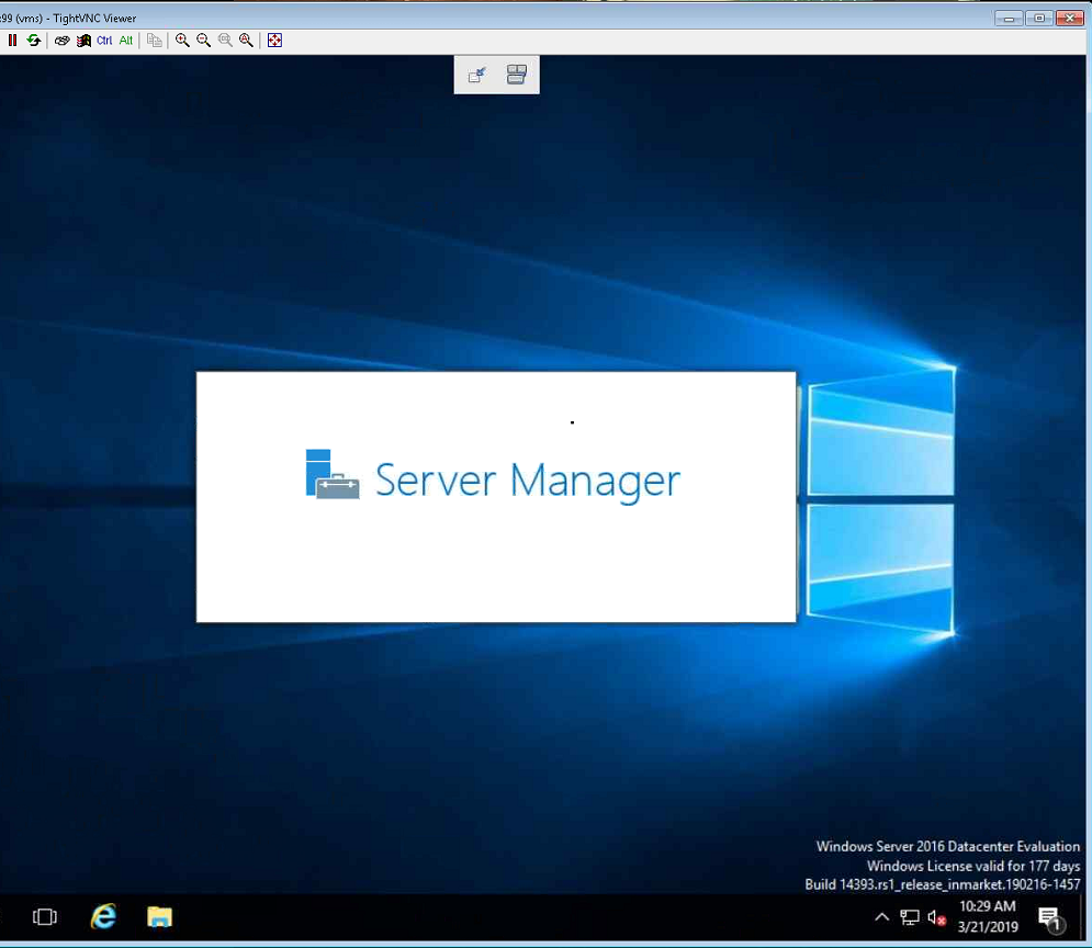
WARNING: As noted in the bottom-right corner of the screen, the Windows version provided is a 180-day trial. Quantum Customers are responsible for obtaining a Windows license. If not, Windows will not be accessible after the trial period expires.
Step 8: Identify Network Connections and Configure CameraNet Interfaces
To see existing network interfaces, on the desktop, right-click on the Windows icon and select Network Connections.
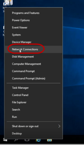
The Network Connections dialog is displayed.
Note: Five network interfaces are available. Not all interfaces are configured to a network.
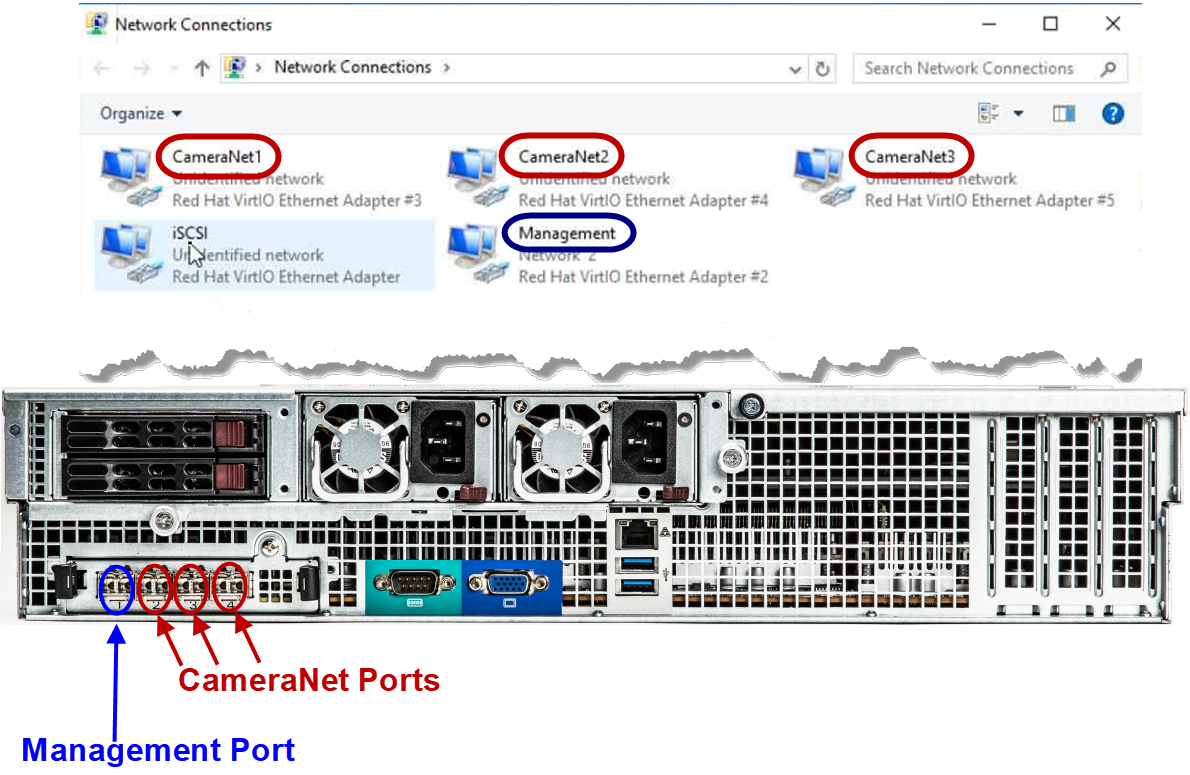
WARNING: DO NOT change the iSCSI port settings. This is an internal network only.
Note: The physical Management Port (interface set to DHCP by default) is the far-left Ethernet port (Port 1 as numbered on the rear panel) of the four ports on the lower-left rear panel of the server.
Configure Camera Interfaces
- To configure a static IP address instead of using the default DHCP settings (optional), if required by your company for the Management interface, double-click on Management.
- Configure the CameraNet interfaces as needed for your company's network and physically connect to the server CameraNet ports.
Note: The CameraNet1, CameraNet2, and CameraNet3 interfaces (set by default to DHCP) are mapped in Windows to the remaining three physical 10 GB Ethernet ports (left to right) on the physical server. The three CameraNet ports may also be bonded together in Windows to allow for a single network, allowing faster data throughput. Bonded network port settings may also require configuration changes in the customer network switch for these ports.