|
|
Connect the QXS RAID Chassis to the Expansion Chassis |

Note: This does not apply to Xcellis Foundation systems, since the system is shipped with a single QXS RAID chassis and no expansion chassis. For systems, continue to Connect the Power Cables and Power on the QXS Chassis.
After the QXS SFPs have been installed, you can connect the SAS cables between the RAID and expansion chassis, as appropriate. If your configuration does not include expansion, continue to Connect the Power Cables and Power on the QXS Chassis.
Considerations
Before cabling the chassis, review the following information.
- Keep in mind that QXS chassis support 6-Gbit/s expansion port data rates.
Some 6-Gbit/s disks may not consistently support a 6-Gbit/s transfer rate. In such cases, the system automatically adjusts transfer rates to those disks to 3-Gbit/s. This adjustment increases reliability and reduces error messages with little impact on system performance. In addition, this adjustment persists until the RAID chassis is power-cycled.
-
Use only Quantum or OEM-qualified SAS cables appropriate for connecting the drive chassis.
- Use cables providing 6-Gbit/s data rate for each lane with four lanes (4x) per SAS connector:
When connecting a RAID chassis to an expansion chassis, the cable length should not exceed 2.0 meters.
When connecting chassis to one another, cable lengths should not exceed 2.0 meters.
-
You can use qualified cables of 0.6 meter length for cabling stacked components in cascaded fashion
-
You may need to order additional or longer cables when reverse-cabling a fault-tolerant configuration.
-
You must purchase required cables if they are not included with your order.
-
You will connect the RAID chassis to expansion chassis with mini-SAS to SAS cables.
Note: For clarity, the images in this topic show only relevant details such as face-plate outlines and expansion ports.
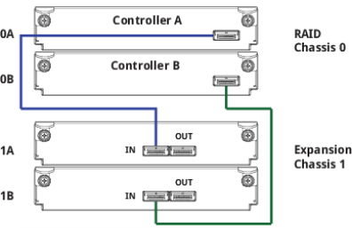
Cable the RAID Chassis to the Expansion Chassis as shown in the following image.
- Use the reverse cabling method shown in the following image to ensure the highest level of fault tolerance.
This cabling method enables the RAID Chassis to maintain access to other Expansion Chassis if any Expansion Chassis fails or is removed.
- Note the following:
- The upper RAID Controller I/O Module is connected to the upper Expansion Controller I/O Module.
- For 12 and 24 drive chassis, Controller A and B are located as indicated in the following diagram.
- For 56 drive chassis, Controller A is located on the right side of the RAID chassis, and Controller B is located of the left side of the RAID chassis, as viewed from the back of the chassis.
- Consult with Quantum technical support when mixing and matching the QXS-3 and QXS-4 Series expansion chassis.
Figure 1: SAS Cabe Connections Between a QXS RAID Chassis with Dual Controller I/O Modules and an Expansion Chassis
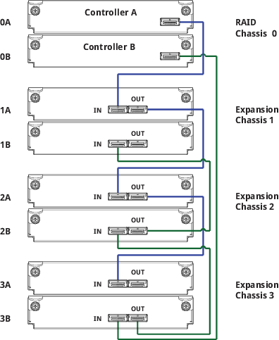
Cable the RAID Chassis to the Expansion Chassis as shown in the following image.
- Use the reverse cabling method shown in the following image to ensure the highest level of fault tolerance.
This cabling method enables the RAID Chassis to maintain access to other Expansion Chassis if any Expansion Chassis fails or is removed.
- Note the following:
- Controller I/O Module 0A is connected to expansion module 1A, with a chain of connections cascading down (blue).
- Controller I/O Module 0B is connected to the lowest expansion module of the last drive chassis, with connections returning to the RAID chassis, in the opposite direction (green).
- Consult with Quantum technical support when mixing and matching the QXS-3 and QXS-4 Series expansion chassis.
Figure 2: Reverse Cabling Connections Between a RAID Chassis with Dual Controller I/O Modules and 3 Expansion Chassis
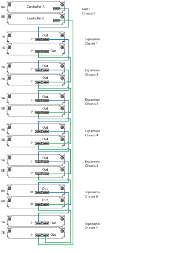
Cable the RAID Chassis to the Expansion Chassis as shown in the following image.
- Use the reverse cabling method shown in the following image to ensure the highest level of fault tolerance.
This cabling method enables the RAID Chassis to maintain access to other Expansion Chassis if any Expansion Chassis fails or is removed.
- Note the following:
- Controller I/O Module 0A is connected to expansion module 1A, with a chain of connections cascading down (blue).
- Controller I/O Module 0B is connected to the lowest expansion module of the last drive chassis, with connections returning to the RAID chassis, in the opposite direction (green).
- Consult with Quantum technical support when mixing and matching the QXS-3 and QXS-4 Series expansion chassis.
Figure 3: Reverse cabling between a dual-controller RAID chassis and 7 expansion chassis
Continue to Connect the Power Cables and Power on the QXS Chassis >>
* Back to Checklist: QXS Chassis Installation *
* Back to Xcellis Foundation Hardware Installation Overview and Checklist (for systems). *
*Back to Hardware Installation Overview and Checklist *