Install System into the Data Center
|
|
How to Create a PDF |
When a customer orders the Quantum R3000 System, it ships in two boxes:
- A box for the drive magazine
- A box for the chassis
The system includes the following components:
- Chassis (with power supply, fan, and circuit boards)
- Drive magazine (with six drives installed)
- Drives (2.5" SSDs or 3.5" HDDs)
- Applicable cables (power and 4 Ethernet cables)
Additional Information
- The drive magazine will need to be installed into the chassis at the site.
- The system ships with the six (6) drives installed in the drive magazine and configured as RAID 5. The customer will have to mount the file system and also set up NFS once installed within the vehicle.
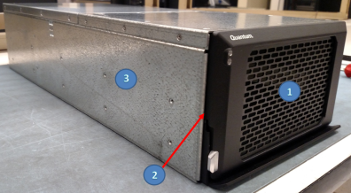
| Item | Description |
|---|---|
| 1 | Drive Magazine |
| 2 | Drives (6 drives each in Drive Magazine) |
| 3 | Chassis |
- Locate the drive magazine box (drive magazine boxes shown below).
Drive magazine box is smaller than the chassis box.
Drive magazine box dimensions:
Shipping Specifications Height 10.5 inches (26.67 cm) Width 13.5 inches (34.29 cm) Length 13.5 inches (34.29 cm) 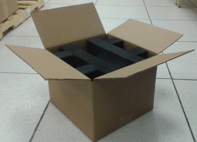
- Remove the drive magazine from the shipping box.
- Place on an ESD mat.
- Locate the chassis box (chassis boxes shown below).
Chassis box is larger than the drive magazine box.
Chassis box dimensions:
Shipping Specifications Height 10.5 inches (26.67 cm) Width 16.25 inches (41.28 cm) Length 25.5 inches (64.77 cm) 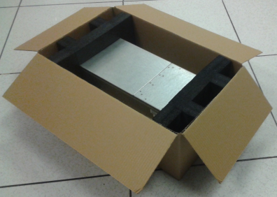
- Remove the chassis from the shipping box.
- Place on an ESD mat.
You can either install the R3000 onto a tabletop (or another flat surface) or into a rack cabinet using a rack shelf that was designed for the R3000. Ensure the drive magazine in not installed within the chassis.
Install Rack Shelf and Chassis into a Cabinet
Note: Before installing the rack shelf within a cabinet, ensure you have enough “U” space to allow installation of the rack shelf. Also, ensure you have enough "U" space to install the chassis on to the rack shelf (chassis height is 5.25 inches, 12.34 cm, 3U).
The chassis height is 5.25 inches (12.34 cm, 3U) and the rack shelf thickness is 1.375 inches (3.5 cm, .9U).
- You must combine the height of the chassis and the rack shelf for installation.
- The height of the chassis 5.25 inches (12.34 cm, 3U) and the thickness of the rack shelf 1.375 inches (3.5 cm, .9U) equals 6.625 inches (16.8 cm, 3.8U).
- This requires at least 4U of rack space for this system to accommodate the chassis and rack dimensions.
Complete the following procedure to in stall the rack shelf and chassis into a cabinet.
-
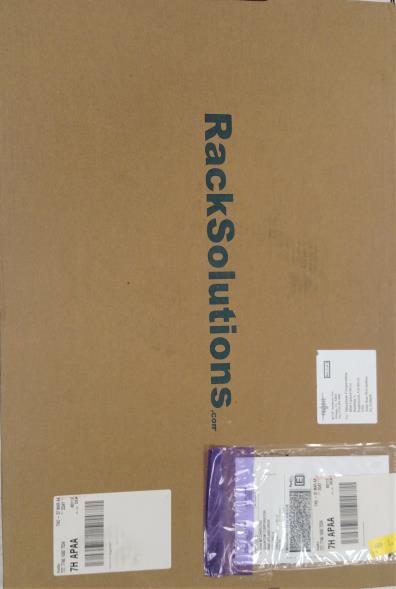
Locate the rack shelf (flat and thin box).
-
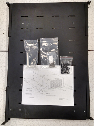
Remove the rack shelf, hardware, and diagram from its shipping box.
-
Inventory all the rack shipping contents (including all sections of the rack, brackets, nuts and screws/bolts).
-
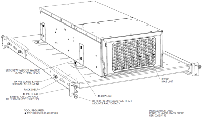
Locate the diagram titled “Installation DWG - R3000 Chassis to Rack Shelf”; review the diagram.
-
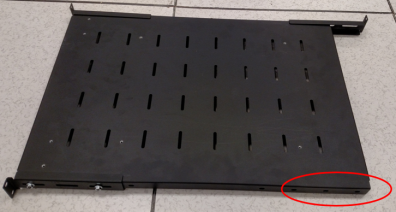
Remove the right-rear extender from the rack shelf.
- This enables the rack shelf to be installed into the cabinet (if only 4U of space is available).
- This step might not be necessary if the cabinet has 5U or more space available for the rack shelf installation.
-
Move the left-rear extender screws to the two back two holes on the rack shelf.
-
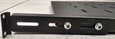
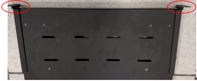
Adjust the two front extenders on the rack shelf to the position as shown below.
Tighten the two screws in each front extender to secure them to the rack shelf.
-
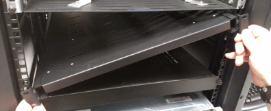
Tilt the rack shelf and place it within the cabinet.
-
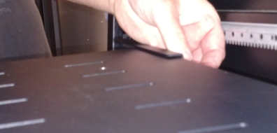
Install the right-rear extender onto the rack shelf (if removed previously).
-
Insert two nut-plates in the front of the cabinet to mount the rack shelf.

-
Insert two nut-plates in the rear of the cabinet to mount the rack shelf.

- Secure the two front extenders (two screws each side of rack shelf) to the cabinet.

- Secure the two rear extenders (two screws each side of rack shelf) to the cabinet.

-
Ensure you have enough “U” space to allow for the chassis on the rack shelf.
Note: The height of the chassis 5.25 inches (12.34 cm, 3U) and the thickness of the rack shelf 1.375 inches (3.5 cm, .9U) equals 6.625 inches (16.8 cm, 3.8U). Allow 4U of rack space to install the chassis and rack shelf.
-
Install two L-brackets on the left side of the chassis as shown below (second and last set of pre-drilled holes from front of chassis).

-
Install two L-brackets on the right side of the chassis as shown below (second and last set of pre-drilled holes from front of chassis).

-
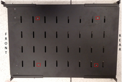
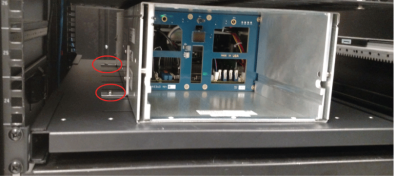
Refer to rack shelf below for the four pre-drilled holes used to secure the L-brackets (chassis) to the rack shelf.
-
Slide the chassis onto the rack shelf.
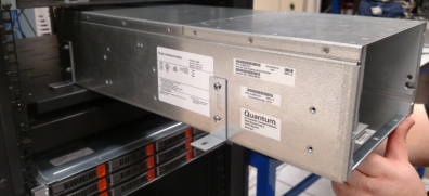
- Align the L-brackets screw holes as close to the pre-drilled holes of the rack shelf as possible.
- Install a single screw (loosely) into one of the L-brackets and rack shelf.
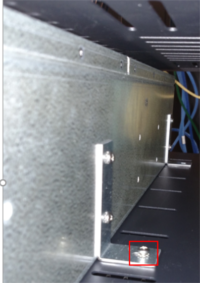
- Install the other three screws into the L-brackets and tighten all four screws.
Left side of R3000: screws located within the L-brackets.
Rear of R3000: screws located within the L-brackets.
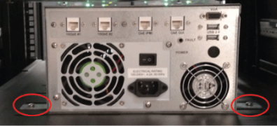
That completes the installation of the rack shelf and the chassis into a cabinet.
To install the drive magazine within the chassis, complete the following steps.
-
Ensure the drive magazine handle is in the fully up position.
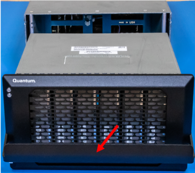
- Align the drive magazine with the chassis.
- Place one hand on the handle and the other hand under the drive magazine.
-
Slowly slide the drive magazine into the chassis.
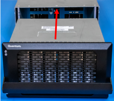
-
Slide the drive magazine into the chassis until it stops.
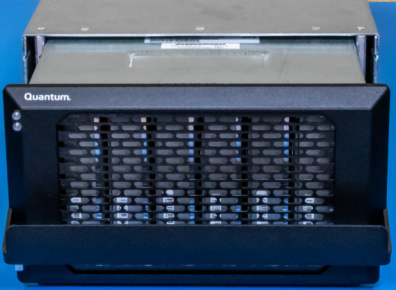
- Push on the front of the drive magazine while pushing down on the handle to lock the unit in the chassis.
-
Ensure the quick-release lock (Callout 3) on the front-left side of the drive magazine handle pops out.
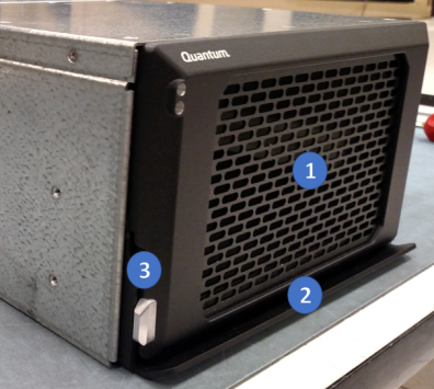
Item Description 1 Drive Magazine 2 Handle 3 Quick-Release Lock - Verify that the quick-release lock is engaged and the handle/drive magazine is locked in place.
-
Locate the labels on the back of the chassis and ensure the power switch (Callout 5) is in the off position (0).
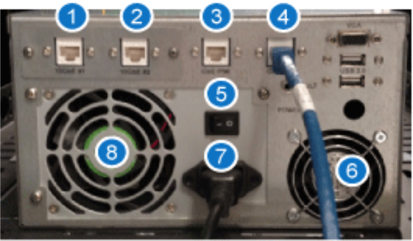
Item Description 1 10GbE RJ-45 Data Port 1 2 10GbE RJ-45 Data Port 2 3 IPMI RJ-45 1GbE Port 4 GUI RJ-45 1GbE Port 5 Power Switch 6 Chassis Cooling Fan 7 100-240 VAC 8 Fan - Connect the following cables to the rear of the chassis as shown above.
- 1GbE GUI cable: Callout 4 (direct connect from laptop/computer)
- 100-240VAC power cable: Callout 7
Note: The system above uses AC (voltage range: 100-240VAC, 2-4A, 50-60Hz).
Once the system is installed within the rack or placed on a data center table, you are ready to power-on the system.
Note: Once power is applied to the unit, the system automatically powers up. If the system does not power up, the power switch might be in the "OFF" position. Refer to the following steps to turn "ON" the power switch.
Complete the following to turn "ON" the system power switch on and AC system.
-
Locate the power switch and move it to the "1" (ON) position.
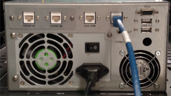
Item Description 1 10GbE RJ-45 Data Port 1 2 10GbE RJ-45 Data Port 2 3 IPMI RJ-45 1GbE Port 4 GUI RJ-45 1GbE Port 5 Power Switch 6 Chassis Cooling Fan 7 100-240 VAC 8 Fan -
If the system does not power up, verify input voltage and/or check input power connections.
Note: The condition where cycling the power switch activates the system is when power is already applied, the system has been shut down (e.g. for a magazine change), and access to the IPMI is not available. In this case, cycling the power switch will re-activate the system.
The following events occur:
- The fan in the power supply and the fan begins to spin.
- The green light on the front (top-left) of the system illuminates.
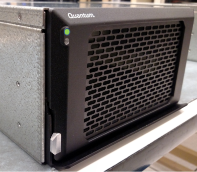
Note: The blue light on the front of the system blinks when data is transferred to/from the system.
Note: Quantum recommends that you configure your R3000 on the same subnet as your target system (example: Xcellis).
Note: The system ships with the six (6) drives installed, configured as RAID 5, and has a label name of "QMSMAG".
The OMV/GUI is an out-of-the-box NAS solution that everyone can install and administer without needing expert level knowledge of networking and storage systems.
-
The system is built on a modular design and can be easily extended with plugins available right after installation of the base system.
- This documentation center provides guidance on using the basics features of the OMV/GUI with the R3000.
- For documentation about additional menu options, refer to the OMV open source documentation: https://openmediavault.readthedocs.io/en/latest/
Configure the IP addresses. The default IP addresses on the R3000 needs to be changed to addresses that are compatible with your network.
Refer to the following illustration for location of the data ports (two), IPMI port, and GUI port on the rear of the R3000 system.
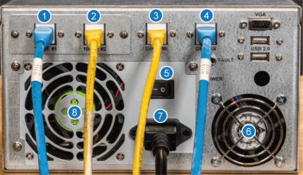
| Item | Description |
|---|---|
| 1 | 10GbE RJ-45 Data Port 1 |
| 2 | 10GbE RJ-45 Data Port 2 |
| 3 | IPMI RJ-45 1GbE Port |
| 4 | GUI RJ-45 1GbE Port |
| 5 | Power Switch |
| 6 | Chassis Cooling Fan |
| 7 | 12 VDC |
| 8 | Power Supply |
The two system 10GbE data port IP addresses and the default GUI and IPMI IP addresses, with default passwords, are shown below.
| Data Ports | |
|---|---|
| eno3 (10 GbE#1) | 10.2.2.1 |
| eno4 (10 GbE#2) | 10.2.2.2 |
| GbE GUI | |
|---|---|
| Default IP address | 10.0.0.1 |
| Default user name | admin |
| Default password | password |
| Subnet mask | 255.255.255.0 |
| GbE IPMI | |
|---|---|
| Default IP address | 10.17.21.51 |
| Default user name | admin |
| Default password | Qa@Ip00! (That is a capital "I", as in India, after the "@" symbol.) |
| Subnet mask | 255.255.255.0 |
Refer to Set Computer to Communicate with System GUI if you need assistance on setting up your computer to communicate with the OMV/GUI.
Note: Change the IP addresses to the designated addresses for you company and/or location. Use the system GUI to change all applicable IP addresses (example: two data ports, and GUI).
Complete the following process to change and/or set up IP addresses.
- Access the GUI (if not already logged in).
- Default Address: 10.0.0.1
- Default Username: admin
- Default Password: password
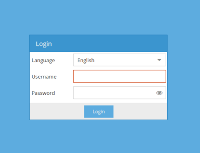
-
Ensure the following screen appears.
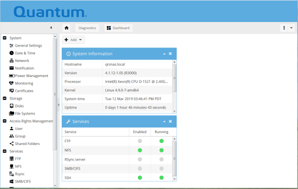
-
Select the following and ensure the following screen appears:
System > Network > Interfaces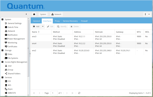
Note: We recommend you configure the ens2 management port (OMV/GUI) first and then refer to the next section to configure the eno3 and en04 (10 GbE data ports).
-
Click the
ens2and clickedit(representative screen when changing ens2 port) and ensure the following screen appears.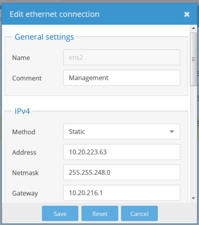
-
Enter the desired
Method, Address, Netmask, and Gateway.Note: The value you enter for the gateway becomes the default gateway for all three ports managed through the OMV/GUI (ens2, eno3, and eno4).
-
Click on "
Save,Apply,Confirm" and ensure the following screen appears.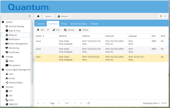
That completes the OMV/GUI IP address change.
-
The address is active as soon as you apply the changes.
-
Currently, after you configure the ens2 (GUI port), you will get an error screen; this basically means you have lost contact with the R3000 and must reconfigure your computer to access the GUI port or access the GUI via the network (new address).
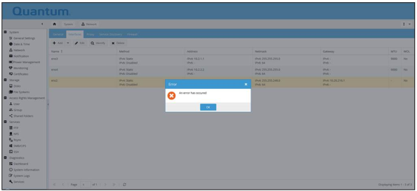
Caution: Do not apply gateways to the 10GbE data ports (eno3 and eno4). If you apply gateways to these ports, you will get an error and will need to contact Quantum Support.
Refer to Set Computer to Communicate with System GUI if you need assistance on setting up your computer to communicate with the OMV/GUI.
Note: Change the IP addresses to the designated addresses for you company and/or location. Use the system GUI to change all applicable IP addresses (example: two data ports, and GUI).
Complete the following process to change and/or set up IP addresses.
- Access the GUI (if not already logged in).

-
Ensure the following screen appears.

-
Select the data port you wish to change (eno3 or eno4) and ensure the following screen appears:
System > Network > Interfaces
-
Click the
en03 or eno4interface and clickedit(representative screen when changing eno4 port) and ensure the following screen appears.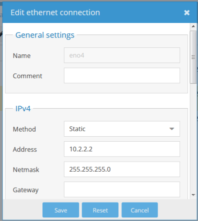
Note: Do not enter a Gateway address as you will get an error and will need to contact Quantum Support.
-
Enter the desired
Method, Address, and Netmask. -
Click on "
Save,Apply,Confirm" and ensure the following screen appears.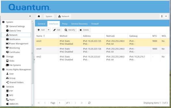
That completes the data port IP addresses change.
-
The address is active as soon as you apply the changes.
-
Repeat the above procedure for the eno4 data port IP address.
Note: Since you have changed the default IP addresses, you will need to direct connect through the GUI port on the back of the system; or, you can access the system via the network.
-
Connect the 10GbE ports, IPMI port (if its network settings were changed), and GUI port to your network.

Item Description 1 10GbE RJ-45 Data Port 1 2 10GbE RJ-45 Data Port 2 3 IPMI RJ-45 1GbE Port 4 GUI RJ-45 1GbE Port 5 Power Switch 6 Chassis Cooling Fan 7 12 VDC 8 Power Supply -
Open a browser and log into the GUI using the new IP address, user name, and password.
- IP address: ______________
- User name: ______________
- Password: ______________

-
The following screen appears.

-
Select Storage > File Systems and ensure you have a file system mounted (QMSMAG).
Note: Factory new magazines have the file system initialized. Creating a file system on the magazine is not needed. If a file system is created, it will take up to 24 hours to complete. If you remove power from the system during file system creation, the file system will become corrupted and will need to be recreated.
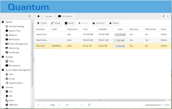
- Set up a share.
Select Access Rights Management > Shared Folders > Add.
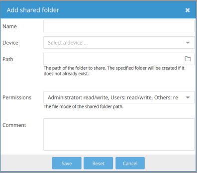
Define a name (Example: QMSShare, no spaces).
From the Device pulldown, select the file system you created (QMSMAG).
The Path will auto-populate with the name you defined above(e.g., QMSShare/).
Click on Permissions pull-down and set permissions (or leave as default or recommended permissions).
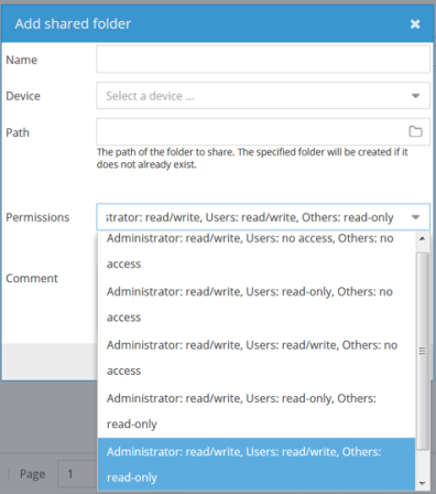
Enter a "Comment" to describe the share or leave blank.
Click
Save,Apply, andConfirm.
- Apply privileges.
In Access Rights Management > Shared Folders, click on the share.
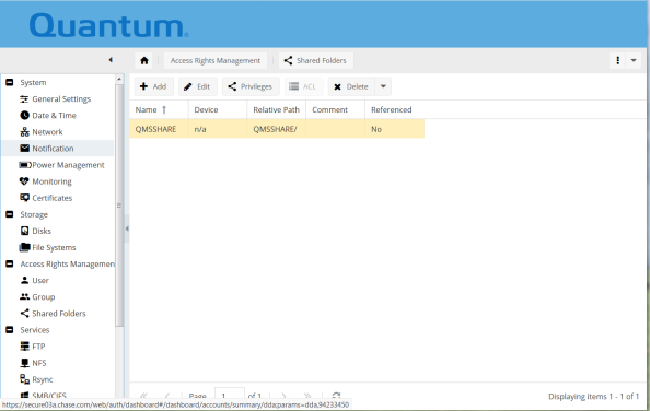
Click the Privileges button.
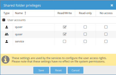
Give Read/Write privileges to user quser and group quser.
Click
Save,Apply, andConfirm.
- Set up a Service (e.g. Network File System [NFS]).
Caution: The R3000, when accessed via the NFS protocol, does not allow the root user of a client system to have access to root privileges on the R3000. When using the NFS protocol, the client system should use the credentials assigned to the share in the
>Access Rights Management>Shared Folders>Privilegesmenu. By default, if the root user of a client system tries to interact with an NFS share, the user’s access to the share will be limited.Refer to the following locations for additional information on other services:
- SMB-CIFS: Set Up a SMB-CIFS Service
- Additional information: https://openmediavault.readthedocs.io/en/latest/
Select Services > NFS.
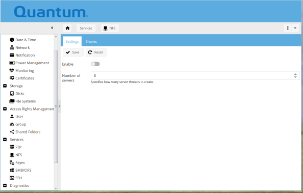
Click the Shares tab and click
Add.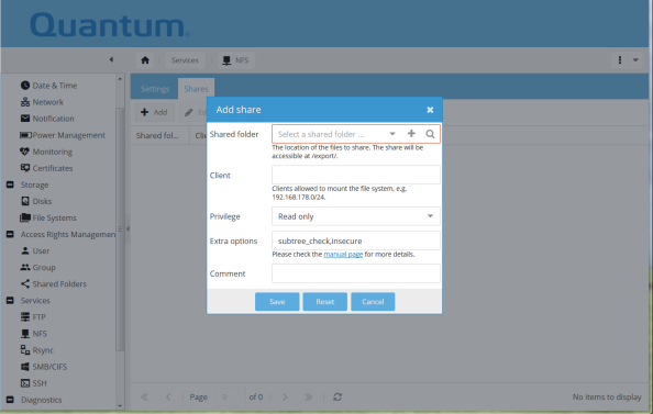
Click on Shared folder drop-down and select the share your created previously (QMSShare).
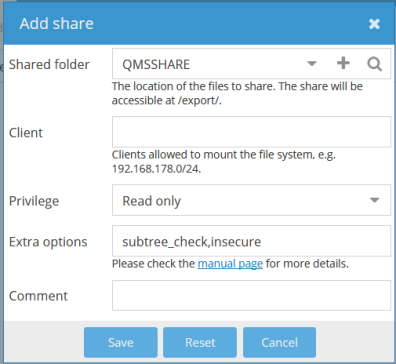
Insert the Client IP addresses (as required) and select Read/Write privileges (as required).
Note: This allows clients to mount the file system.
Leave the "Extra options" default.
Save, Apply, and
Confirmthe configuration changes.
- Enable the Service.
In Services > NFS click the Settings tab.
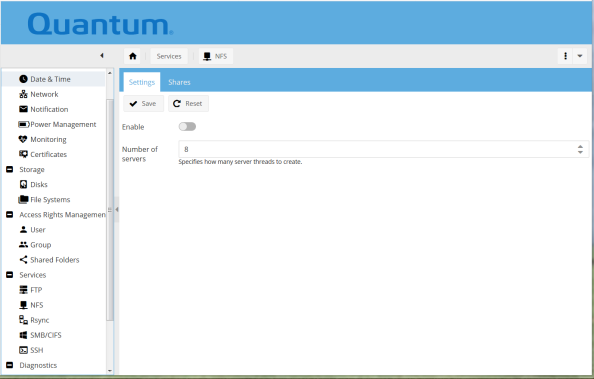
Specify how many server threads to create (or take default of 8).
- Click the Enable toggle.
Save, Apply, and
Confirmthe configuration changes.
Step 8a: Configure FlexSync
Note: You will get best performance for data replication using the 10GbE ports on your R3000 system. Consult with your network administrator to determine the configuration that best suits your requirements.
FlexSync is already installed on the R3000. However, it also needs to be installed on the StorNext appliance (Xcellis) that will serve as your target system.
Before you configure data replication, FlexSync must be installed on your StorNext appliance, which means that you must complete the following two steps, if you haven’t already.
-
Obtain and Install the FlexSync License - If you need to obtain and install a FlexSync license on your StorNext appliance, refer to the “Before you Install FlexSync” section of the FlexSync Documentation Center.
FlexSync uses a count-type license.
- The count in the license file is the number of hosts expected to be required for all activity.
- You must install the license on the MDC where the FlexSync administrative daemon process (flexsyncadmind) is running, which is where the license check is performed.
- If any of the Tasks are between more than one MDC pair, the only pair that requires the FlexSync license is the one with the running FlexSync administrative daemon process.
Note: You must install the StorNext license file that includes the number of hosts (data movers) available to perform replication tasks on the Xcellis or M-series appliance that you are using to configure your FlexSync replication tasks.
-
Install FlexSync on your StorNext appliance - If you need to install FlexSync on the StorNext appliance (Xcellis), refer to the “Install FlexSync” section of the FlexSync Documentation Center.
Below is a glance at the key steps with some basic information to help you understand the process.
- Step 1: Download the FlexSync installer file
- Step 2: Install or upgrade the FlexSync application
- Step 3: Activate FlexSync daemons
- Step 4: Manage FlexSync users
We will assume you have completed steps 1 - 3 above, and start with creating a FlexSync user on your target (Xcellis) system. If you need further information about completing steps 1-3, refer the FlexSync Documentation Center.
Additional Information
- Log in to your Xcellis (using Xcellis login credentials) to create a FlexSync user and the user’s login credentials.
- Later, when you want to configure FlexSync on your Xcellis, you will log in the Xcellis (using FlexSync login credentials) to open the FlexSync dashboard.
- You will create the user twice, once using the flexsyncd daemon, and once using the flexsyncadmind daemon.
- The FlexSync user credentials (login, password) that you create on the Xcellis will also need to be used when you create a FlexSync user on the R3000.
Information required (this refers to your Xcellis, so we can’t provide it):
- IP address for the Xcellis system: _______________
- Login for the Xcellis system through SSH: _______________
- Password for the Xcellis system through SSH: _______________
- You will create FlexSync login credentials. You may wish to record them here, as you will use the same credentials when you create the FlexSync user on the R3000.
- Login: _______________ (example: TJONES)
- Password: _______________ (example: TjPassword!)
-
Open an SSH client (PuTTY, Terminal.app, etc.), and connect to your target StorNext system.
-
At the command prompt, enter the following command to create a FlexSync user account for the FlexSync service using the flexsyncd daemon:
Command format
/opt/quantum/flexsync/bin/flexsyncauth -a -U <USERNAME> -P <PASSWORD> -d <daemon>Example
/opt/quantum/flexsync/bin/flexsyncauth -a -U TJONES -P TjPassword! -d flexsyncd -
Repeat the command using the flexsyncadmind daemon:
Example
/opt/quantum/flexsync/bin/flexsyncauth -a -U TJONES -P TjPassword! -d flexsyncadmind -
You can use the following command to check that you have successfully created a user:
Command format
/opt/quantum/flexsync/bin/flexsyncauth -l -d <daemon>Example
/opt/quantum/flexsync/bin/flexsyncauth -l -d flexsyncdor
/opt/quantum/flexsync/bin/flexsyncauth -l -d flexsyncadmind
Your R3000 also needs to have a FlexSync user.
-
The FlexSync user you create on the R3000 needs to have the same login credentials as the FlexSync user you just created on the Xcellis.
- Information required:
- IP address for the R3000: ______________
- Login for the R3000 through SSH (default: quser): ______________
- Password for the R3000 through SSH (default: password): ______________
- You will create login credentials for FlexSync user that match those used on the FlexSync system.
- Login (example: TJONES): ______________
- Password (example: TjPassword!): ______________
-
Open an SSH client (PuTTY, Terminal.app, etc.), and connect to your R3000 system.
Login using the
quseraccount. -
You need to use
sudoto execute these commands on the R3000.You will be asked to re-enter the password (password) every time you execute a command using sudo.
-
At the command prompt, enter the following command to create a FlexSync user account for the FlexSync service:
sudo /opt/quantum/flexsync/bin/flexsyncauth -a -U <USERNAME> -P <PASSWORD> -d <daemon>
Example
sudo /opt/quantum/flexsync/bin/flexsyncauth -a -U TJONES -P TjPassword! -d flexsyncd
- You can use the following command to check that you have successfully created a user:
Command Format
sudo /opt/quantum/flexsync/bin/flexsyncauth -l -d <daemon>Example
sudo /opt/quantum/flexsync/bin/flexsyncauth -l -d flexsyncd - Next you need to use the FlexSync user to login to the FlexSync GUI on your Xcellis and complete the basic configuration.
IP Address: ______________
Username (Example: TJONES): ______________
Password (Example: TjPassword!): ______________
Note: Not all browsers are supported by FlexSync. We recommend Google Chrome version 58 or later, or Apple macOS Safari version 10 or later.
There are three basic steps to configure FlexSync to replicate your data.
To begin, log in to the FlexSync dashboard.
- Open a browser, and enter the Xcellis IP address followed by the FlexSync port number (9091).
- For example: 10.0.0.1:9091.
- Use the FlexSync user credentials to log in.
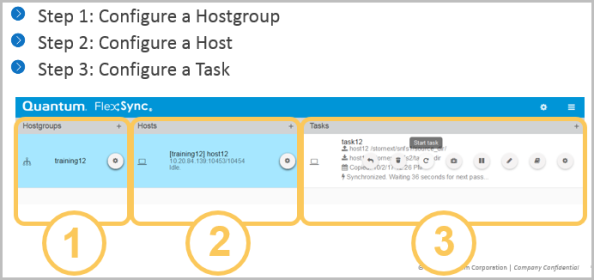
Note: We provide default settings for the hostgroup, hosts, and task you will create. Most users will not need to modify these settings. For information about advanced settings refer to the following: FlexSync Documentation Center
The hostgroup is a container for the hosts that will be the source and target systems.
-
If you have multiple systems you want to replicate, you can configure multiple Hostgroups.
-
To start configuring FlexSync, you must first add a hostgroup.
-
Click the plus button in the Hostgroups column.
-
In the Add a hostgroup window, enter a hostgroup label in the Name field.
-
Click "
Submit".The FlexSync dashboard displays your configured hostgroup in the Hostgroup column.
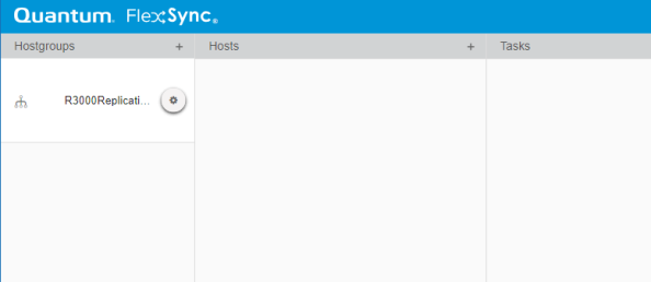
Two hosts need to be added to your hostgroup. You will perform the procedure described below twice: once for the Xcellis (the target), and once for the R3000 (the source).
-
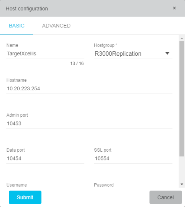
Select your hostgroup and then click the plus button in the Hosts column. The Host configuration Basic tab window appears.
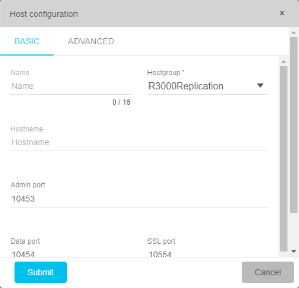
- Complete the fields in the Host configuration window under the
Basictab:- Enter a label for a host in the
Namefield (Example: TargetXcellis or SourceR3000). - Select a hostgroup from the
Hostgroupdrop-down list. The hostgroup that you just created will appear in the list. - Enter the IP address of your host in the
Hostnamefield. - The default settings for the Admin port - used for management communications, the Data port - used for data port communications and the SSL port - used for SSL communications can be changed or left at the default values.
- Scroll down and enter the FlexSync
usernameandpassword.
- Enter a label for a host in the
- Click Submit.
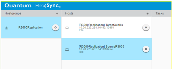
- Ensure the FlexSync dashboard now displays your configured hosts in the Hosts column.
- Repeat the procedure for the other host.
If you configured the target host first, now configure the source host. If you first configured the source host, now configure the target host.
Note: After creating the two hosts, the FlexSync dashboard should resemble the figure below.
A Task defines defines which files and directories to replicate from the source system (the R3000) to a location you choose on the target system(s) (Xcellis).
-
To configure a task, select your hostgroup and one of the hosts (it doesn’t matter which one), and then click the plus sign in the Tasks column to start configuring a task.
-
Ensure the Task configuration window appears.
- Complete the fields in the Basic Settings tab.
- Enter a label for the task in the Task name field.
- From the Source drop-down list, select your source host.
- In the
/source/pathfield, enter the file system mount and relative path of the source host to replicate.
Format:
/srv/dev-disk-by-label-QMSMAG/<sharename>/Example:
/srv/dev-disk-by-label-QMSMAG/QMSSHARE/Note: A forward slash at the end of the path tells the system to replicate all the files within the source directory. If you do not include the last forward slash, it will replicate the source directory and all of its contents.
- From the Destination drop-down list, select the destination (or target) host.
- In the /destination/path field, enter the file system mount and relative path of the destination host to replicate data to.
Note:
/destination/pathis configured by the Xcellis user; we can’t tell you what it is. You can find the file system mount in an SSH client using the command:mount | grep cvfs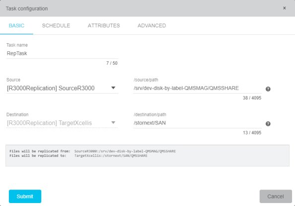
Note: The target directory does not need to exist; the system will automatically create the directory if you did not include the last forward slash in the source directory path field.
-
Click the
Scheduletab to display the Schedule tab items. You may modifiy these items or keep them at their default settings.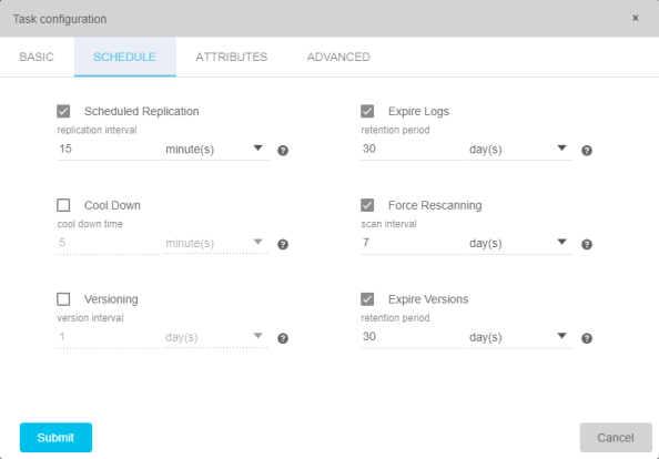
Make sure the Scheduled Replication box is checked to schedule replication.
Replication IntervalThe is the time between replication passes.
- If the current pass takes longer than this, the next pass will start immediately after the current pass ends.
- The default time is 15 minutes, entering 0 disables replication intervals.
Log RetentionThe minimum amount of time before a replication pass log is deleted.
- The default time is 30 days, enter 0 to keep logs forever.
Cool Down TimeThe minimum file age before a file is replicated.
- Use this setting to skip replication of temporary files.
- The default is 0, which disables this setting.
Forced Scan IntervalThe number of days to force file system scans.
- FlexSync does not scan the file system with every replication pass.
- The default is 0, which disables this setting.
Version IntervalThe smallest interval between version creations of replicated data.
The default is 0, which disables this setting.
- Click
Submit.
Step 8b: Configure for Non-StorNext Solution
Note: If you are not using StorNext, you can use FTP, SSH, NFS, SMB, and RSync from your data center to mount and retrieve data.

