minute read
Drive Replacement
Use this procedure to replace a tape drive in a Scalar i6000 library.
If a drive fails, the library will issue a RAS ticket. From the RAS ticket, write down the Repair Link or Error Code number.
WARNING:
-
Before performing any of the steps listed in this document, contact Quantum Service for help diagnosing the problem.
-
To use this procedure, all drives must be connected to an Ethernet Expansion Blade (EEB) or an FC I/O blade.
Before You Begin
Important Information - Drive Acclimation
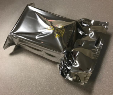
Before opening the sealed ESD bag, the drive should be acclimated to the climate inside the facility or room location where the drive will be installed. Changes in temperature and humidity can cause condensation. It is recommended to leave drives in the packaging for a minimum of 24 hours before opening the sealed bag.
Place the sealed bag away from direct sources of air convection to minimize condensation.
If any external or internal condensation is seen on the sealed bag after 24 hours, remove the drive from the bag and acclimate the drive in the planned location for an extra 12 to 24 hours, or until no visible condensation remains.
Figure 1: Drive in Sealed Bag
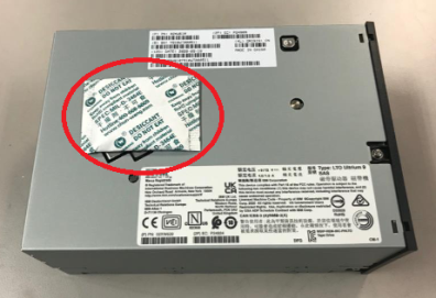
Once the bag has been opened, the drive should never be moved to a new location where temperature differences are greater than 5 degrees Celsius. If this type of drive relocation needs to occur, the drive should be placed in a sealed bag with desiccant and allowed to acclimate to the new location for a minimum of four hours.
Figure 2: Drive with Dessicant
Drive temperature and humidity specifications are as follows:
Note: The temperature and humidity specifications below are for LTO drives. For LTO media temperature and humidity specifications, refer to the Environmental Specifications in the Site Planning Guide.
| Mode | Air Inlet Temperature | Relative Humidity (Non-Condensing) | Altitude (Max) |
|---|---|---|---|
| Operating Mode |
10°C to 40°C (50°F to 104°F) |
20% to 80% 26°C (79°F) Wet Bulb Max |
3048 m |
| Recommended Operating Mode |
20°C to 25°C (68°F to 77°F) |
40% to 50% | 3048 m |
| Storage |
-40°C to 60°C (-40°F to 140°F) |
10% to 90% Non-Condensing |
3048 m |
| Shipping |
-40°C to 60°C (-40°F to 140°F) |
10% to 90% Non-Condensing |
12192 m |
Locating a Drive
When a drive fails, a RAS ticket is generated by the library that will identify the malfunctioning drive using a coordinate system. This section will explain the basics of locating a drive using the coordinate system so when you are replacing the drive, you will be able to identify the correct drive. Removing a drive incorrectly can impact data on your library.
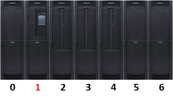
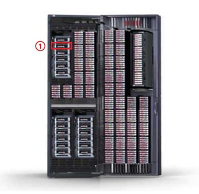
The drive coordinate system has five (5) numbers. In the example below, we are going to locate a drive with the coordinates 1,1,11,1,1 in a library that is configured with the following:
-
1 Left Parking Module (LPM)
-
1 Control Module (CM)
-
4 Expansion Modules (EM)
-
1 Right Parking Module (RPM)
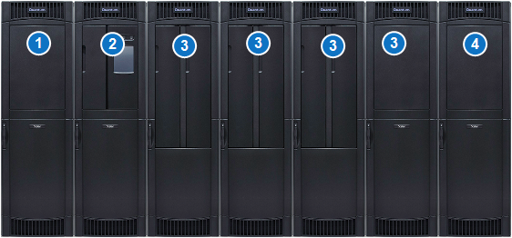
| Item | Name |
|---|---|
| 1 | Left Parking Module (LPM) |
| 2 | Control Module (CM) |
| 3 | Expansion Modules (EMs) |
| 4 | Right Parking Module (RPM) |
Important Information: 6 Drive Number Coordinates
In the LMC and some RAS tickets there will be 6 coordinate numbers. The first number in a six number coordinates is the aisle number and will always be one. Disregard this number and read the next 5 numbers in the drive coordinate. For example, a coordinate that is displayed as 1,1,1,1,2,1 in the LMC or RAS ticket should be read as 1,1,1,2,1.
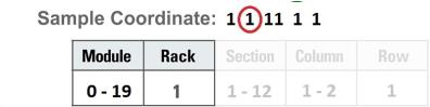
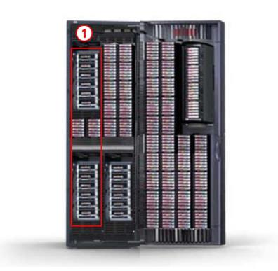
The first number in the sequence identifies the module. The module number can be from 0-19. This applies to both single- and dual-robot libraries. The left parking module (module 0) is only for dual-robot libraries and cannot contain drives. A high-density expansion module (HDEM) also cannot contain drives.
A maximum of 18 drives can be installed in each control module (CM) and a DREM can contain a maximum of 24 drives
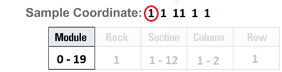
The second number in the sequence represents the rack. Since drives can only be contained in rack 1, this number will always be 1.
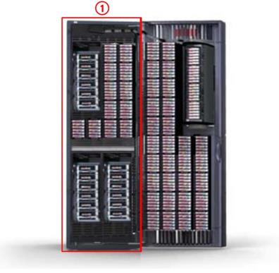
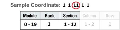
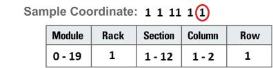
The third number in the sequence indicates the section. Each control module can contain 18 drives so with drives, this number can range from 1-12 in each column. Drives are counted from bottom to top.
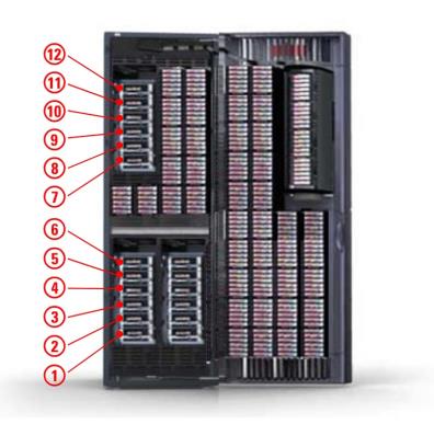
The fourth number in the sequence identifies the column. Since drives can only be contained in a single column, they will always reside in column 1 or 2.

The fifth number in the sequence denotes the row and will always be 1. Drives have a connection point at the lower portion of the drive sled that connects to the library. Therefore, the sled is logically in row 1.
Remove and Replace the Drive
This procedure is used to replace a drive with the same drive model. Drive upgrades must be performed by Quantum service personnel. If the failed drive is an EDLM drive, it must be replaced by Quantum service personnel.
Caution: Before starting this procedure, verify that you have received the same make and model drive as the drive you are replacing. The outside of the box will indicate the drive make and model that was shipped.
Required tool: Phillips screwdriver - use this if the thumbscrews are too tight.
-
Stop any processes on the host that are communicating with the drive that is being replaced.
-
Log on as an administrator from the library’s touch screen (LMC).
-
Locate the drive identified as needing replacement on your call with Quantum Service:
-
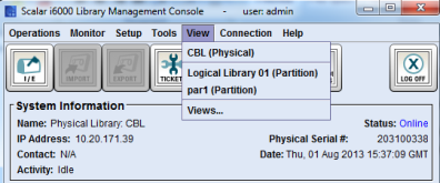
Select View > Physical Library.
-
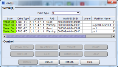
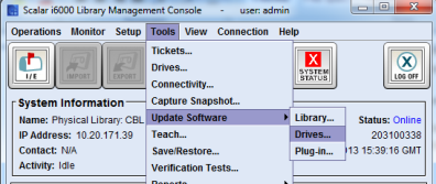
Select Tools > Drives. The Drives screen displays.
-
Using the coordinates, select the drive to be replaced.
-
Scroll over to the Firmware Version column.
-
Write down the four digit firmware level.
-
-
Click Cancel to close the Drives screen.
-
Double check that there is no tape in the drive you are removing. If there is a cartridge in the tape drive:
-
Select View > Partition. You will select the partition that contains the drive you are replacing.
-
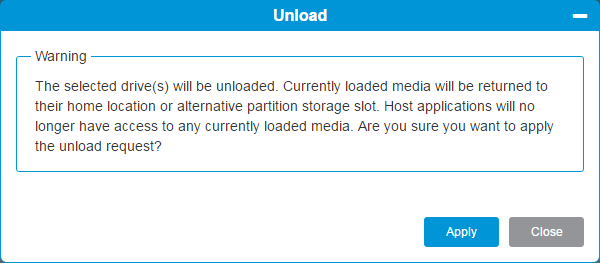
Select Operations > Drives > Unload. This will eject the tape from the drive and return it in its storage slot in the library. If a tape is in the drive and cannot be ejected, call Quantum support before proceeding.
-
-
Go back to library view by selecting View > Physical Library.
-
Select Tools > Drives. The Drives screen displays.
-
Vary off the drive:
-
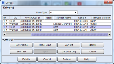
From the Drives screen, use the Drive Type drop-down menu to display the drives by drive type.
-
Select the drive, and then click Vary Off.
-
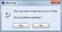
Click Yes.
-
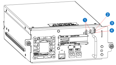
Go to the rear of the module containing the drive to be replaced, open the back door, locate the drive using the coordinates from the ticket and observe the blue LED on the rear of the drive. When the blue LED stops blinking and remains constantly lit, you can continue.
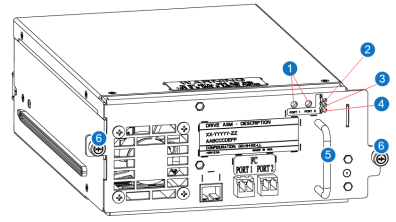
Item Name 1 Green Port LED1 2 Blue LED 3 Amber LED 4 Green LED 2 5 Drive Handle 6 Thumbscrews
-
-
Disconnect all cables from the drive. Note which cables go to which connections for reference during drive replacement.
-
Loosen the two thumbscrews on the drive.
-
Grip the drive handle and pull the drive toward you to remove it.
-
Use the guide rails on the replacement drive to slowly slide it in until flush.
-
Tighten the two thumbscrews.
-
Reconnect the cables.
-
Confirm the following status LEDs:
-
Blue LED light on the back of the drive is constantly lit.
-
Green LED 2 light on the back of the drive is blinking slowly and in cadence with the LEDs on the other drives.
Note: The LEDs should take less than 5 minutes to get to this state.
-
-
If the LEDs are displaying properly, you can vary on the drive. From the Drives screen:
-
Select the newly installed drive.
-
Click the Vary On button.
-
Click Cancel.
-
-
The library may update the drive sled firmware. Wait a few minutes to see if a dialog box appears. If this happens, wait until it is complete before continuing. The drive sled firmware update will take approximately 5 minutes.
-
Go to the rear of the module and observe the drive status LEDs and wait for the following conditions to occur:
-
Green LED 1 - solid green indicating port connectivity to either the FC I/O blade or the customer FC switch.
-
Amber LED - off
-
Blue LED - blinks one time per 10 seconds.
-
Green LED 2 - blinks at the same cadence as the other green LEDs on the other drives in the module.
Item Name 1 Green Port LED1 2 Blue LED 3 Amber LED 4 Green LED 2 Close the access doors.
-
-
Close the ticket that was generated for the failed drive.
-
Stop any processes on the host that are communicating with the drive that is being replaced.
-
Log on to the WebGUI as an administrator.
-
Locate the drive identified as needing replacement on your call with Quantum Service:
-
From the Navigation panel, select Drives.
-
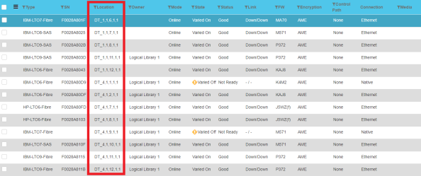
In the North Panel, refer to the drive coordinates under the Location column, and select the check box next to the drive(s) you want to replace.
-
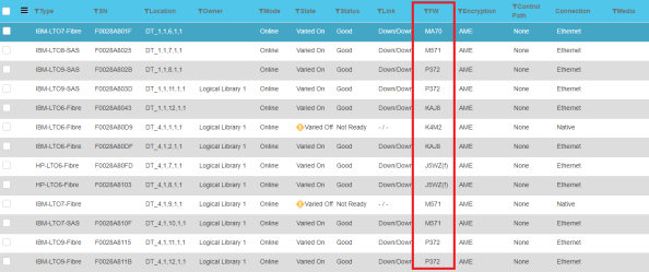
Write down the four digit firmware level located in the FW column.
-
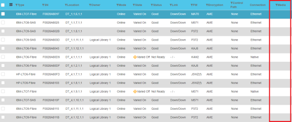
Check the Media column of the selected drive to ensure that there is no tape in the drive you are removing.
If there is a tape in the drive, select Unload from the Operations panel. This will eject the tape from the drive and return it in its storage slot in the library.
Note: If a tape is in the drive and cannot be ejected, call Quantum support before proceeding.

-
-
Vary off the drive:
-
From the Operations panel, select Remove/Vary Off button.
-
Go to the rear of the module containing the drive to be replaced, open the back door, locate the drive using the coordinates from the ticket and observe the blue LED on the rear of the drive. When the blue LED stops blinking and remains constantly lit, you can continue.
Item Name 1 Green Port LED1 2 Blue LED 3 Amber LED 4 Green LED 2 5 Drive Handle 6 Thumbscrews
-
-
Disconnect all cables from the drive. Note which cables go to which connections for reference during drive replacement.
-
Loosen the two thumbscrews on the drive.
-
Grip the drive handle and pull the drive toward you to remove it.
-
Use the guide rails on the replacement drive to slowly slide it in until flush.
-
Tighten the two thumbscrews.
-
Reconnect the cables.
-
Confirm the following status LEDs:
-
Blue LED light on the back of the drive is constantly lit.
-
Green LED 2 light on the back of the drive is blinking slowly and in cadence with the LEDs on the other drives.
Note: The LEDs should take less than 5 minutes to get to this state.
-
-
If the LEDs are displaying properly, you can vary on the drive. From the Drives screen:
-
Select the newly installed drive in the North Panel.
-
Select the Replace/Vary On button in the Operations Panel.
-
-
The library may update the drive sled firmware. The drive sled firmware update will take approximately 5 minutes.
-
Go to the rear of the module and observe the drive status LEDs and wait for the following conditions to occur:
-
Green LED 1 - solid green indicating port connectivity to either the FC I/O blade or the customer FC switch.
-
Amber LED - off
-
Blue LED - blinks one time per 10 seconds.
-
Green LED 2 - blinks at the same cadence as the other green LEDs on the other drives in the module.
Item Name 1 Green Port LED1 2 Blue LED 3 Amber LED 4 Green LED 2
-
-
Close the access doors.
-
Close the RAS ticket that was generated for the failed drive.
Update the Drive Firmware
Important Information
-
This procedure should only be used if drive auto-leveling is turned off.
-
If you are viewing a partition, drive firmware update operations affect drives that are within the partition only.
-
You can only perform firmware updates for drives of the same product, such as IBM LTO-4 or HP LTO-5.
-
If you load a firmware image onto a drive that is the same version that is currently running on the drive, the upgrade will fail.
-
The appropriate drive firmware image must be uploaded to your library prior to beginning the update process (see Update or Remove Drive Firmware).
Federal Information Processing Standard (FIPS) Firmware
FIPS firmware is indicated by _f and (FIPS) in the firmware name.
- FIPS firmware example -
IBM_LTO7_H9E2.fcp_fh_f.fmrz (FIPS) - Non-FIPS firmware example -
IBM_LTO7_G9Q4_fcp_fh.fmrz - Drives in a FIPS partition cannot have non-FIPS firmware loaded.
-
From the View menu, select the partition that contains the replacement drive.
-
Select Tools > Update Software > Drives. A warning dialog box displays stating the partition needs to be taken offline.

-
Click Yes.
-
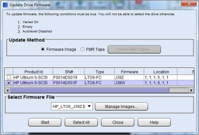
From the Update Drive Firmware screen, ensure the option selected in the Update Method area is set to Firmware Image.
-
Click the check box next to the replacement drive.
-
Compare the four digit firmware level you wrote down earlier with the four digit firmware version listed in the Firmware column of the selected drive. If they match, go to step 12. If not, continue on to step 7.
-
From the Select Firmware File drop-down menu, select the firmware image you want to install.
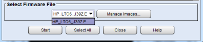
The drop-down list includes all drive firmware images that are currently stored on the library, regardless of drive type. Be careful to select a drive firmware image that is compatible with the type of drive that you want to update. See the library's Release Notes for compatibility information or contact Quantum technical support.
-
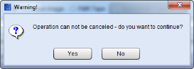
Click Start. A warning dialog box displays stating the operation cannot be canceled.
-
Click Yes. The library automatically logs off other users so they cannot perform library operations while the drive firmware update is in progress.
Note: On the back of the drive, the Green LED 2 will flash rapidly while the firmware update is in progress.
-
The library updates the firmware on the selected drive.Updating drive firmware could take up to 20 minutes to complete.
-
When finished, the Status column of the drive will state Update Complete and the LEDs on the back of the drive will display:
-
Green LED 1 - solid green indicating port connectivity to either the FC I/O blade or the customer FC switch
-
Amber LED - off
-
Blue LED - blinks one time per 10 seconds
-
Green LED 2 - blinks at the same cadence as the other green LEDs on the other drives in the module
-
-
Click Close.
-
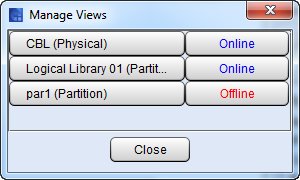
Select View > Views. The Manage Views screen displays.
-
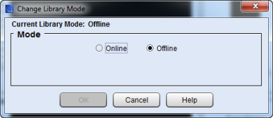
Click the Offline button for the partition that contains the replacement drive. The Change Library Mode screen displays.
-
In the Mode area on the Change Library Mode screen, select Online and click OK. The Manage View dialog shows the partition now Online.

-
Click Close.
-
From your applications, bring the replacement drive online and perform any necessary tests to ensure it is working properly.
-
Call Quantum Service to confirm that drive replacement was successful and to perform any further troubleshooting.
- From the Navigation panel, select Drives.
- In the North Panel, select the check box next to the drive(s) you want to update.
Review the firmware in FW column.
If the firmware matches the previous firmware from replaced drive, go to step 6.
If the firmware does not match the previous firmware from the replaced drive, go to step 3.
-
In the Operations panel, click Firmware Update.
Item Description Action Drive Firmware Area Allows you to select the version of drive firmware you want to use.
Note: If you have Drive Leveling enabled, you cannot manually update drive firmware. See Drive Leveling for details.
Note: If a drive is unassigned, you cannot downgrade drive firmware.
Select the checkbox next to the firmware you want to use. Click Apply to begin updating the drive firmware. Progress Area Displays the drive(s) that are currently being updated, the drive serial number and location as well as status of the update. -
During the drive firmware update, the library automatically logs off other users so they cannot perform library operations while the drive firmware update is in progress. On the back of the drive, the Green LED 2 will flash rapidly while the firmware update is in progress.
-
Click Close to exit the window when the firmware is complete.
-
When finished, the FW column of the drive indicated the new drive firmware version and the LEDs on the back of the drive will display:
-
Green LED 1 - solid green indicating port connectivity to either the FC I/O blade or the customer FC switch.
-
Amber LED - off
-
Blue LED - blinks one time per 10 seconds.
-
Green LED 2 - blinks at the same cadence as the other green LEDs on the other drives in the module.
-
-
From your applications, bring the replacement drive online and perform any necessary tests to ensure it is working properly.
-
Call Quantum Service to confirm that drive replacement was successful and to perform any further troubleshooting.
Note: When the drive replacement is complete, refer to the documentation that was included in the drive packaging for how to return the failed drive to Quantum.