Site Planning Guide
Overview
The Scalar i6000 library automates the retrieval, storage, and control of cartridges. The cartridges are mounted and retrieved from tape drives using a robotic assembly that is driven by application software from the host without operator intervention. The library is designed for ease of installation, configuration, and field upgrades.
- For Gen2, dual-robot systems using i11, the two robots work in an Active/Active manner, where both robots are available to perform all move commands and operations. Also new for i11 is the availability of High-Density Expansion Modules (HDEM) that allow for increased media storage.
- Dual robotics libraries require special modules on either end called parking modules, which house the robots when not in use.
- You can upgrade an existing single robotics library (Gen 1 or Gen 2) to a Gen 2 dual-robotics library and you can also upgrade a Gen 1 library to a Gen 2 library.
- You can tell which generation robot you have via the library WebGUI. The library displays which generation of robot hardware is installed. Select Devices from the Navigation menu and then select a robot from the North Panel. In the Information panel, the Description will list what generation the robot is.
- The library can be installed on a solid or a raised floor. The library has a standard 19-inch rack footprint and can be placed in a standard server rack space. Access is from doors located at the front and back so the library can be placed with either side against a wall, or between racks.
- To determine what generation electronics your library is running, select Monitor > System from the menu, click the Components tab and look in the Name column. If you have MCB2 and RCU2, you have Gen2 electronics. Any other MCB or RCU level means Gen1 electronics.
- The maximum library can be configured to accommodate from 100 LTO cartridges to 7,146 LTO cartridges (for a single-robot library) or 7,224 LTO cartridges (for a dual-robot library). For libraries containing high-density expansion modules, the maximum capacities are 12,006 LTO cartridges (for a single-robot library) or 11,760 LTO cartridges (for dual-robot libraries).
Select the following Scalar tape library license agreements below:
Components
Aisle lights are used to illuminate the inside of a module and can be used in conjunction with a webcam to monitor activity within the library. Aisle lights can be configured to turn on at various time intervals and for specific durations. If a webcam is installed, the aisle lights will turn on automatically when the webcam is accessed and turn off when stopped.
Additional Information
- Aisle lights are available for i2000/i6000 libraries. However, not all i2000’s have the necessary hardware features. The Control Module serial number in your i2000/i6000 library configuration must be at least 203102253 or begin with 263.
- For the aisle lights to automatically come on when the webcam is accessed, the minimum library firmware code is i10.2 (640Q.GS08801).
- An aisle light cannot be in the same frame as a webcam.
All libraries contain a control module. A single-frame library consists of a control module only. The control module manages library operations via the library management module and includes an operator panel touch screen for local operator use.
The control module always occupies module position 1 in the library. (In dual-robot configurations, the left parking module is in position 0.)
Additional Information
- A control module can only contain a 24-slot I/E station.
- Series 3 modules require i12.2.1 or later firmware as well as Gen2 electronics and robotics.
Control modules in dual-robotics libraries can take advantage of two columns of storage (up to 14 additional magazines) that are unavailable in single-robotics configurations. Extra magazine slots are only available if the drive slots are not in use.
A dual-robotics library requires Gen 2 robotics hardware. A dual-robot library requires, at a minimum, a control module, a left parking module, and a right parking module.
For a dual-robot library that includes an HDEM, it requires, at a minimum, a left parking module (shipped with dual-robots), a control module, an HDEM and a right parking module.
The left and right parking modules have the same size and appearance as standard expansion modules, but they function differently. Each parking module contains a “parking space” in which the respective left or right robot resides when not in use. The parking space occupies four magazine columns which cannot be used for storage.
The left parking module is located to the left of the control module in position zero. It is referred to in the user interface as “module 0.” The left parking module does not contain tape drives, I/E stations, or power supplies. The control module supplies it’s power. If you are upgrading to dual-robotics, you will receive a left parking module to add onto your existing system (the LPM and second robot ship together when ordering the Dual Robot option). This increases your system size, so you must take this into account when planning for an upgrade.
The right parking module is a converted SEM or DREM and is the right-most module in the system. As with standard expansion modules, in i11 the right parking module may contain a maximum of 12 drives, power supplies, and up to one 24-slot I/E station no matter how may frames make up the library. The only restrictions are that right parking modules may not contain a 72-slot I/E station and an HDEM cannot be used as a right parking module.
If you are upgrading a single-robot library to a dual-robot library, the existing right-most expansion module can, in most cases, be converted into a right parking module. However, if the existing right-most expansion module contains a 72-slot I/E station or is an HDEM, you will need another module to be added to the right of your system which becomes the right parking module. If space considerations prohibit the addition of another module, then the right-most module will be swapped with another module in the library that does not contain a 72-slot I/E station.
The Scalar i6000 supports library managed encryption systems. These encryption systems use a centralized key manager application to generate, protect, store, and manage encryption keys. These keys are used by HP or IBM LTO-4 or later tape drives to encrypt information being written to, and decrypt information being read from, tape media. Policy control and keys pass through the library-to-drive interface; therefore encryption is transparent to the host application software.
You must have an Encryption Key Management (EKM) license installed on the library to encrypting data using library managed encryption.
The Scalar i6000 supports the following encryption key management systems.
| Encryption System | Supported Tape Drives |
|---|---|
| Quantum Encryption Key Manager (Q-EKM) Must purchase Q-EKM library licenses per tape drive used1. |
|
| Scalar Key Manager (SKM) Must purchase SKM library licenses per tape drive used1. |
|
| SafeNet key management (KMIP-compliant) (Not provided) Must purchase 3rd party library licenses per tape drive used1. |
|
| Thales Must purchase 3rd party library licenses per tape drive used1. |
|
| IBM TKLM Must purchase 3rd party library licenses per tape drive used1. |
|
| 1Encryption license keys are activated for the number of drives installed in the library. These license keys are library licenses and do not transfer with the tape drives. | |
Note: The library does not support using more than one encryption key management server on a single library.
Expansion modules enable the library to expand by adding space for tape drives, an I/E station, and storage. Each expansion module from 96 to 780 LTO cartridge slots depending on the number of tape drives installed and whether an I/E station is installed.
Quantum offers three different expansion modules (EMs) used with the Scalar i6000:
| Expansion Module | Description |
|---|---|
| Drive Ready Expansion Module (DREM) |
This module is required when drives will be installed into the module. It has the power and network components needed to support tape drives. The DREM supports up to 24 tape drives and up to 456 cartridge slots, but the slots are reduced when drives or an I/E station are installed in the module. A new Series 3 DREM (DREM3) module was introduced with the i12.2.1 code base. DREM3 modules installed in libraries with Gen2 robots, Gen2 electronics and running 12.2.1 or higher code will support up to 24 tape drives. |
| Storage Expansion Module (SEM) |
This module is used when drives will not be installed in the module and high-density is not needed. While the SEM does not support drives, it can be field upgraded to a DREM if drives are needed in the future. The SEM supports up to 456 cartridge slots, but the slots are reduced when an I/E station is installed in the module. A new Series 3 SEM (SEM3) module was introduced with the i12.2.1 code base. SEM3 modules can be field converted to a DREM3. |
| High-Density Expansion Module (HDEM) |
This module is used when it is important to minimize the floor space. The HDEM supports up to 780 cartridge slots, but does not support drives. The slots are reduced when an I/E station is installed in the module. |
Note: When referencing expansion modules in all Scalar i6000 documentation it includes all three module types: drive-ready, storage and high-density. When referencing standard expansion modules, it includes just the drive-ready and storage expansion modules. Parking Modules are also used to expand the library, but these modules are only used when the dual-robot is installed
The library control path is used to send SCSI commands to the library. The Scalar i6000 offers several different control path options:
| Control Path Option | Description |
|---|---|
| HP and IBM LTO-5 or later Native Fibre Channel (Ethernet Expansion Blade included) |
A tape drive hosts the library control path and forwards media changer commands to the library controller. Commands for both the tape drive and the library are received by the drive. This shared SCSI protocol link uses the Fibre Channel connection on the drive so a dedicated port for library control is not needed. You must have at least one HP or IBM LTO-5 or later FC drive installed in the library. The drive must be attached to an Ethernet Expansion blade. For more information, see the Scalar i6000 User’s Guide. Additional Information
|
| HP LTO-5 and LTO-6 drives support control path connectivity in version i8 and higher. | IBM LTO-5 and later drives support control path connectivity in version i12 and higher and only with Gen2 libraries (robot and electronics). |
| Path Failover (previously Native Storage Networking (nSNW)) (Ethernet Expansion Blade Attached) | Path failover can be used to provide redundant or multiple control paths. A tape drive hosts the library control path and forwards media changer commands to the library controller. Commands for both the tape drive and the library are received by the drive. This shared SCSI connection uses the Fibre Channel connection on the drive so a dedicated port for library control is not needed. Path failover licenses can be added to a library that has IBM or HP nFC LTO-5 or higher drives. If control path failover is used, a minimum of two path failover licenses are required. The control path fails over to the second port on a drive and then to another drive that is configured for control path failover. If a customer is interested in minimizing the ports used on their FC switches, the second port on the drives do not need to be used. In this case, the failover would go directly from the primary drive to the failover drive. |
| Storage Networking (SNW) (Fibre Channel I/O Blade Attached) |
The host connects to the library through a dedicated 4 Gb FC port on an FC I/O blade. However, using I/O blades in the data path prevents the use of EEBs and path failover licenses. A second, dedicated 4 Gb FC port on the FC I/O blade can be used for control path failover. Drives must be SNW tape drives and attached to an FC I/O blade. |
| Library MCB Port (not available for versions i10.x or higher) |
The MCB has one dedicated 1 Gb FC port that can be used for host connectivity. This port can be used even if the nSNW or SNW options are purchased. Note: This port is not supported in version i10.x or higher. If upgrading a library to i10.x, a newer generation drive or I/O blade may need to be ordered to provide a supported library control path. |
The data paths are used to send commands and data to tape drives. The Scalar i6000 offers three different data path options:
| Data Path Option | Description |
|---|---|
| Native Fibre Channel (nFC) (Direct Attach) |
Depending on the LTO generation, LTO tape drives include a single FC port or dual FC port. On dual port drives, port A is the default active port. Dual port drives include:
Single port drives include:
|
| Serial Attached SCSI (SAS) (Direct Attach) |
|
| Path Failover (Previously Native Storage Networking (nSNW) (Ethernet Expansion Blade Attached) | Applies to nSNW HP LTO-5 FC or LTO-6 drives connected to an Ethernet Expansion blade only. The native 8 Gb FC port on the drive is used. These drives also support basic or advanced data path failover using a second FC port on the tape drive, so if you want to use data path failover, two ports per drive are required. |
| Storage Networking (SNW) (Fibre Channel I/O Blade Attached) | The data paths connect to the library through a dedicated 4 Gb FC port on an FC I/O blade. Drives must be SNW tape drives and attached to an FC I/O blade. Up to four tape drives can be supported per FC I/O blade. |
Path Failover (previously Native Storage Networking or nSNW) is a set of features that increase control path and data path availability. There are three path failover options:
- Advanced Path Failover for IBM LTO-5 and later drives
- Advanced Path Failover for HP LTO-6 drives
- Basic Path Failover for IBM and HP LTO-5 and later drives
Advanced path failover supports multiple FC fabrics and requires a specific Quantum driver installed on host computers.
Basic path failover either uses 1) NPIV technology supporting a single FC fabric with no driver needed or 2) the path management solution of the application.
All three path failover options support library control path and/or data path failover. IBM and HP LTO-5 and later drives have two FC ports on the drive. When a path failover license is added to the library, the second FC port on one drive is enabled. The second port is needed for data path failover but is not necessary for control path failover.
The control path fails over to the second port on a drive and then to another drive that is configured for CPF. If a customer is interested in minimizing the ports used on their FC switches, the second port on the drives do not need to be used. In this case, the failover would go directly from the primary drive to the failover drive.
The library management interface uses an 10/100 Ethernet port on the MCB for network connectivity. For i11.x, the MCB 2.0 is available with a 1 Gb Ethernet port and for i12.x, the MCB 2.0 has two 1 Gb Ethernet ports. This port is shared for connectivity of the remote user interface and any encryption key management solution used for library managed encryption.
Libraries running 815 libary firmware and above support the Ethernet Management Blade (EMB). The EMB combines the functionality of both the CMB and EEB into one blade. The EMB provides both Ethernet connectivity to tape drives (CMB + EMB) in addition to local CAN bus communication (CMB) to drive sleds.
The EMB removes the I/O Management Chassis that contains the CMB and EEBs and replaces it with an EMB chassis.
The I/O management unit is an optional component that provides connectivity and data path management to a SAN fabric and the hosts. The I/O management unit houses up to four FC I/O blades, which provide FC connections for the Fibre Channel drives in the module.
The I/O management unit also houses up to two Ethernet Expansion blades, which handle internal Ethernet communication between the MCB and LTO-5 and later drives. (The control module and each of the expansion modules can contain up to 12 FC drives.) The I/O management unit performs all tape drive and library host communication functions in a library that is attached to a SAN.
When FC I/O blades or Ethernet Expansion Blades (EEBs) are installed in the library, the following rules regarding control management blades (CMBs) apply:
Any module (including the control module) that contains FC I/O blades or EEBs must also contain a CMB.
A CMB must be installed in the control module and all modules that contain drives. Modules that don’t contain drives, blades or network chassis will contain drive and network jumpers that maintain communications between the MCB located in the control module and the modules that contain drives, FC I/O blades and EEBs.
I/O management units may be installed in the control module and expansion modules. The I/O management unit supports the following blades:
The CMB performs unit status monitoring including power and I/O present conditions, and internal network switch functions connecting I/O blades with the library management module.
There is a single Fibre Channel (FC) I/O blade type: 7404 that auto-negotiates up to 4 Gbps. Each FC I/O blade has an embedded controller that provides connectivity and features that enhance the performance and reliability of tape operations. Each blade provides two host communication ports and four connection ports to drives.
Additional Information
- Fibre Channel LTO-1, LTO-2, LTO-3, LTO-4, LTO-5, LTO-6, LTO-7, LTO-8, LTO-9, and LTO-10 drives can be connected to drive-aggregating Fibre Channel I/O blades or directly attached to a host. If library firmware is at level 630Q or later, DLT tape drives are no longer supported.
- We recommend that you connect directly to the host FC to take advantage of the maximum possible throughput.
The EEB provides the option for Ethernet connectivity to each LTO-5 or later drive (for MCB-to-drive communication purposes only). The EEB provides a control path to the drive for commands as well as facilitates taking drive logs and downloading drive firmware. Each EEB has 6 Ethernet ports to allow attachment to 6 LTO-5 or later drives. The EEB provides Ethernet connectivity to the library's internal Ethernet only and should not be connected to an external Ethernet source.
I/E stations enable you to import and export cartridges without interrupting normal library operation. There are two types of I/E stations:
- 24-slot
- 72-slot.
Each 24-slot I/E station has a capacity of 24 LTO cartridges that are located in four removable magazines. The 72-slot I/E station consists of two side-by-side 36-slot I/E stations that can operate independently or as a single 72-slot I/E station. Each 36-slot I/E station provides I/E capacity of 36 LTO cartridges in six removable magazines.
The I/E station is installed on the front of the control module or any of the standard expansion modules or HDEMs and a 24-slot I/E station can be installed in a right parking module.
Additional Information
- The I/E station cannot be configured as a storage location, but can be part of a a logical division of library resources known as partitions.
- Libraries running 830 firmware and above allows the configuration of more than 240 I/E element addresses. For libraries running firmware below 830, the maximum number of I/E element addresses in any partition is 240. This includes both physical slots and extended I/E virtual slots.
The library management module is located in the control module. It controls system hardware and enables external devices to perform configuration and obtain system status. The library management module contains the following boards:
| Board | Description |
|---|---|
| Management control blade (MCB) |
Manages the library, passing commands to and from the robotics control unit as well as the storage area network (SAN) components. It is also the interface for managing the library remotely and handles encryption key management (EKM). Note: An MCB 2.0 is required for any system to upgrade to i11.x. |
| Robotics control unit (RCU) |
Controls the picker and accessor functionality. Note: An RCU 2.0 is required for any Gen 2 system to upgrade to i11.1.1 or greater. |
| Library motor drive (LMD) (Gen 1 libraries only) | Distributes power to the picker along with the X and Y-axis circuits. It also distributes power to the touch screen. |
| Library power control (LPC) (Gen 2 libraries only) | Distributes power to the robot through the power rails. It also distributes power to the touch screen. |
The operator panel is located on the front of the control module and consists of, buttons, indicators and a touch screen.
Buttons and Indicators
The buttons are for library control and power while the indicators provide library status.
| Robotics Enabled | This feature allows you bring a robot offline and back online. The robotics is automatically disabled when aisle doors on the system are opened. |
| Status |
Indicates current library status.
|
| Power | Turns on and off all power for the control module and attached expansion modules. See Power System below. |
Touch Screen
The touch screen is the library navigation point and provides access to the Library Management Console (LMC). The LMC consists of five primary areas:
- Title bar–provides the library name
- Menu bar–provides menu access to all library management commands
- Tool bar–provides quick access to the most commonly executed functions
- Library information panel–provides real-time library information
- Overall system status–provides real-time status information for the six subsystems of the physical library
The library supports single and redundant power configurations. The single configuration has either a single AC or DC line input with a single DC power supply. The redundant configuration has either a dual AC or DC line input with dual DC power supplies. You can hot swap a power supply if you have a redundant power supply. You can hot add a second power supply.
Note: Power supplies cannot be mixed with other power supplies. AC power supplies and power distribution units must be housed in an AC power chassis and DC power supplies and power distribution units must be housed in a DC power chassis.
The power system may consist of the following:
A single power switch, located on the front door of the control module, turns on and off all power for the control module and attached expansion modules. Each power distribution unit has a second circuit breaker, located in the rear of the module, that controls the module power supply output. The power supply has three LEDs that provide status information. The power system also has four fuses for system protection.
The control module and all expansion modules or right parking modules that contain drives must contain a power system. If an expansion module or right parking module contains only cartridges, its power is derived from the control module and a power system is not needed.
The robot moves cartridges between storage cells, tape drives, and the I/E station. A picker is used to get or put cartridges in a storage cell or a tape drive slot. The picker moves along an X and Y axis and can pivot 180 degrees. A barcode scanner on the picker assembly identifies cartridges located in storage cells. The library can be configured for either one or two robots.
There are two types of slot capacities in Scalar i6000: physical capacity and licensed capacity. Physical capacity is added to a library by adding expansion modules to a configuration. Either DREMs, SEMs or HDEMs can be added, depending on the need.
Capacity on Demand allows you to purchase and license physical slots in 100-slot blocks. Any number of slots can be licensed between 100 and 12,000. You do not need to license all the physical slots, but only licensed slots can be assigned to host managed partitions. It is often desirable to have more physical slots installed than will be licensed.
Expansion modules are sold separately from the slot licensing. This separation provides the flexibility to order the exact modules needed (DREM, SEM or HDEM).
Note: Maximum numbers assume only one drive and one 24-slot I/E station in the control module.
To gain the use of additional storage slots, you must purchase a Capacity on Demand license for the desired number of slots. Expansion modules may also be needed to add more physical capacity.
Active Vault and Extended Data Lifecycle Management (EDLM) features do not require the use of licensed slots. You may purchase additional expansion modules to accommodate these features without the need to increase your COD license.
The Tower Barcode Scanner is an optional upgrade for the HDEM. One scanner can be installed in each HDEM and is used to inventory cartridges residing on the tower. The scanner improves operations by conducting all inventory operations on the tower independent of the rest of the library. Thus all tower inventory operations (e.g., library initialization, cartridge imports, or cartridge moves) have little or no impact on other library operations.
A webcam is an optional component that can be installed to any expansion module within a library. In conjunction with aisle lights, a webcam is used to monitor activity within the library.
Requirements for installing a webcam include:
- External 110v power source
- Cable from external Ethernet port to webcam interface module
- Aisle lights
- Scalar i6000, Gen2 robotics, version 10.2 or higher
- If the webcam port is not in use, it can be used as a Fire Suppression port (see Fire Suppression).
Additional Information
- It is recommended that version i10.2 be used so that the aisle lights turn on automatically when the webcam is activated. Previous versions will require that the aisle lights be turned on independently from the webcam.
- Webcams are available for i2000/i6000 libraries. However, not all i2000’s have the necessary hardware features. The Control Module serial number in your i2000/i6000 library configuration must be at least 203102253 or begin with 263.
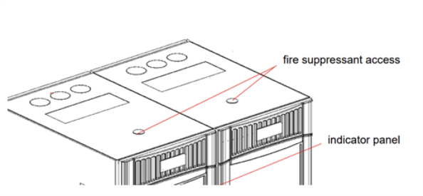
If an optional webcam is not installed in an expansion module, the webcam port can be used to install a fire suppression system. The port has the following specifications:
-
Port Width: The webcam/fire supression port has a maximum width of 1.75 inches (44.5 mm).
-
Maximum Installation Depth: The maximum depth that a fire suppression system can extend into the library is 2.48 inches (63 mm).
Specifications
Quantum recommends a 6 + 2 barcode format (for example, 6 digits plus 2 characters assigned as the standard LTO media identifier) that follows the label standard ANSI MH10.8M-1983. For advanced uses, your Quantum library supports label lengths of up to 16 characters allowing you to create custom labels. You may wish to use special labels on cleaning tapes to make them easier to distinguish from data tapes.
The use of high-quality labels is critical for trouble-free system operation. Quantum strongly recommends that you purchase pre-printed barcode labels from your media supplier or another trusted source. For added convenience, consider purchasing pre-labeled media.
The use of high-quality labels is critical for trouble-free system operation. Quantum strongly recommends that you purchase pre-printed barcode labels from your media supplier or another trusted source. For added convenience, consider purchasing pre-labeled media.
Quantum tape libraries support media barcode labels per USS-39 (Code-39) specification. Quantum recommends the use of a 6 + 2 barcode format (6-character barcode, followed by a 2-character media identifier) that meet labeling and print quality standards ANSI MH10.8M-1983 and ANSI X3.182. Barcode labels require a matte finish (no glossy reflection).
Quantum tape libraries support barcode lengths from 5 to 15 characters, inclusive of any optional media identifiers. Barcode labels may embed an RFID tag but may not include checksum characters.
- Proper barcode label identification can be affected when using barcodes longer than 13 characters in length as print quality becomes even more important for longer labels that need to fit within the tape cartridge’s recessed area where the label is affixed.
- For Scalar i40, i80 and i500 tape libraries: A maximum of 12 characters is recommended to allow the camera/scanner system to read media barcodes reliably when created/printed for the limited space to where the label is affixed to the tape cartridge.
The use of high-quality labels is critical for reliable system operation. Quantum branded, pre-labeled media can be ordered from Quantum or any other trusted source such as Tri-Optic. Regardless of barcode label source, media barcode labels are supported if the labels meet the following requirements:
- Labeling standard: ISO/IEC 16388:2007 (formerly ANSI MH10.8M-1983)
- Barcode print quality – Guideline: ISO/IEC 15416:2016 (formerly ANSI X3.182 -1990 (R2000))
- Symbology: Code 39 (3 of 9).
- Characters: uppercase letters A to Z, numeric values 0 to 9.
- Special characters “%”, “$”, “+”, “-“, “.” and space “ “
- Number of characters: 5 to 15, including media identification. No checksum characters.
- Barcode quality: ANSI Grade A and B.
- Barcode symbol Height: greater than 8 mm.
- Background reflection: greater than 75%
- Barcode symbol reflection: less than 25%
- Print contrast: greater than 75%
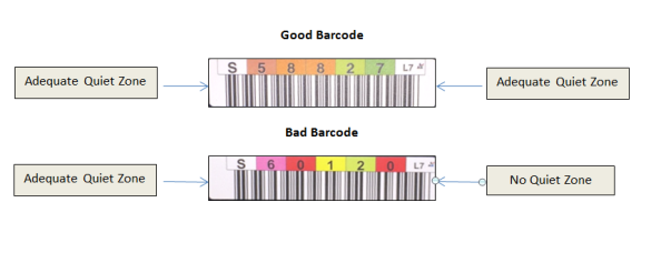
- Quiet zones: 5.25 mm, ± 0.5 mm.
-
Print quality: no print defects.
- No visible black marks/spots in background spaces or rest zones.
- Not more than 5 visible voids or white spots on barcode symbols with a combined total of less than 0.25 mm².
- No scratches, smudge or scuff marks on background or barcode.
- No visible blotchy spots affecting label reflection on background or barcode symbols.
-
Barcode label application. Barcode labels:
- Should be applied and read in a uniform direction.
- Must be attached horizontally and centrally within recessed label area.
-
Additional barcode label provider requirements: Barcode label providers should test and validate barcode labels for use in Quantum tape library products to assure the following:
- Intermec EV12 and EV14 scanners mounted at an angle of about 10 degrees, pointing down, at a distance of about 6 inches from the tape cartridge.
- Report a minimum of 5 “scans” when scanning vertically at a scan speed of 30 cm/sec.; with each reported scan being comprised of 2 consecutive and identical scanner reads.
Additional Information
- Quantum strongly recommends using labels with a matte finish, such as the recommended Tri-Optic barcode labels, rather than a high gloss finish as glossiness as well as blotchy spots affect reliable scanner operation.
- Glossiness can be observed by reflecting a bright light directly, straight onto the label or by taking a flash picture and checking for wash out.
- Glossiness of Quantum recommended Tri-Optic labels were measured with a Zehntner Glossmeter (model ZGM 1020) and had gloss values < 10.
If you wish to print the barcode labels, the individual media labels are supported if the labels meet the following requirements:
- ANSI MH10.8M-1983 Standard.
- Type font: Code 39 (3 of 9).
- Characters: Only uppercase letters A to Z and/or numeric values 0 to 9.
- Number of digits: 5 to 16 (default for LTO is 6+2).
Note: A maximum of 12 characters is recommended. A barcode label with more than 12 characters may not be printable according to the Code 39 label specifications for the tape cartridge area to which the label is attached. The effective tape cartridge barcode label length, including any media ID, may be limited to a maximum of 12 characters.
- Background reflection: greater than 25 percent.
- Print contrast: greater than 75 percent.
- Ratio: greater than 2.2.
- Module: .254 mm (10 mil).
- Print tolerance: ± 57 mm.
- Length of the rest zones: 5.25 mm ± 0.25 mm.
- No black marks may be present in the intermediate spaces or rest zones.
- No white areas may be present on the bars.
- Bars should read in a uniform direction. Non-uniform reading directions are feasible in principle, but have a detrimental effect on performance.
- Each label should be applied in the upper right corner of the tape cartridge recess (when oriented vertically).
- Checksum characters are not supported on barcode labels.
Compliance with these specifications can be checked and documented with the Ergilaser 3000 High Density barcode measuring device that is manufactured by the Laetus Company.
Additional Information
- Quantum strongly recommends using labels with a matte finish, such as the Quantum recommended Tri-Optic barcode labels, rather than a high gloss finish for more reliable scanner readability.
- Glossiness can be observed by reflecting a bright light on the label or by taking a flash picture and checking for wash out
- While no industry ratified spec is available for glossiness, for reference Quantum recommended Tri-Optic labels were measured with a Zehntner Glossmeter (model ZGM 1020) and had Gloss Values < 10
- Quantum branded, pre-labeled media can be ordered from Quantum or you can order customer labels from Tri-Optic
Printed Barcode Examples
| Connection | Connector | Speed |
|---|---|---|
| Fibre Channel drive (control path bridging; IBM LTO-10only) | LC | 32 Gbps |
| Fibre Channel drive (control path bridging; IBM LTO-5 and later and HP LTO-5 and LTO-6 only) | LC | 8 Gbps |
| Fibre Channel on FC I/O Blade (tape drives can be connected to the I/O blade but is not required to use the I/O blade for control path communications) | LC | 4 Gbps (7404) |
| Ethernet on System Control Blade (SCB) | RJ45 | 1 Gb |
Note: Scalar i6000 uses single phase power only. Three phase power is not supported.
| Scalar i6000 Modules | Amp @ 110V | Amp @ 220V | Min Watts | Max Watts | Min BTU/Hr |
Max BTU/Hr |
|---|---|---|---|---|---|---|
|
Control Module (CM3)¹ As shipped. Includes:
|
2.35 | 1.13 | 237 | 247 | 808 | 842 |
| Storage Expansion Module (SEM3) | 0 | 0 | 0 | 0 | 0 | 0 |
|
Drive Expansion Module (DREM3) As shipped. Includes:
|
1.95 | .98 | 212 | 212 | 273 | 723 |
|
High-Density Expansion Module (HDEM) As shipped. Includes:
|
.64 | .32 | 26 | 70 | 89 | 239 |
|
Control Module (CM2)¹ As shipped. Includes:
|
2.62 | 1.31 | 277 | 287 | 945 | 979 |
| Storage Expansion Module (SEM2) | 0 | 0 | 0 | 0 | 0 | 0 |
|
Drive Expansion Module (DREM2) As shipped. Includes:
|
2.32 | 1.15 | 252 | 252 | 859 | 859 |
| Scalar i6000 Options/Upgrades | Amp @ 110V | Amp @ 220V | Min Watts | Max Watts | Min BTU/Hr | Max BTU/Hr |
|---|---|---|---|---|---|---|
| CM3 and DREM3 Redundant Power Supply | .075 | .037 | 8 | 8 | 27 | 27 |
| CM2 and DREM2 Redundant Power Supply | .73 | .36 | 8 | 8 | 27 | 273 |
| HDEM Redundant Power Supply | .1 | .05 | 11 | 11 | 38 | 38 |
| Dual Robot¹ ² | .3 | .15 | 25 | 35 | 85 | 119 |
| HDEM Scanner | .048 | .024 | 3 | 5.28 | 10 | 18 |
| Scalar i6000 Tape Drives | Amp @ 110V | Amp @ 220V | Watts | BTU/Hr |
|---|---|---|---|---|
|
Tape Drive Ethernet Blade (EEB) One EEB should be added for every 6 tape drives (round up). |
.1 | .05 | 10 | 34 |
| IBM LTO-10 Drive (writing)¹ | .47 | .23 | 40 | 136 |
| IBM LTO-10 Drive (no tape) | .36 | .19 | 30 | 102 |
| IBM LTO-9 Drive (writing)¹ | .31 | .16 | 39 | 133 |
| IBM LTO-9 Drive (no tape) | .17 | .16 | 28 | 95 |
| IBM LTO-8 Drive (writing) ¹ | .29 | .15 | 37 | 126 |
| IBM LTO-8 Drive (no tape) | .11 | .10 | 18 | 61 |
| IBM LTO-7 Drive | .32 | .16 | 35 | 119 |
| IBM LTO-6 Drive | .3 | .15 | 34 | 116 |
| IBM LTO-5 Drive | .4 | .2 | 48 | 154 |
| IBM LTO-4 Drive | .35 | .18 | 38 | 130 |
| HP LTO-6 Drive | .25 | .13 | 28 | 96 |
| HP LTO-5 Drive | .25 | .13 | 28 | 96 |
| HP LTO-4 | .3 | .15 | 35 | 119 |
For HDEM and CM3, DREM3 and the applicable 2N option ship worldwide with two power cords
| Cord |
|---|
| L6-20/C19 for North America, 14 ft., Part Number 1-03260-4 |
| IEC 60309/C19 for International, 14 ft., Part Number 1-03260-2 |
For CM2 and DREM2 Modules, one (1) of the following cables will be sent:
| Cord |
|---|
| L6-30 for North America, 14 ft., Part Number 9-02919-01 |
| IEC 60309 for International, 14 ft.,Part Number 9-02925-01 |
Electrical Specifications for HDEM and Series 3 Modules
| Location | Voltage (Single Phase, 50-60 Hz) | Required Protective Service | Delivered Power Connectors | AMPs |
|---|---|---|---|---|
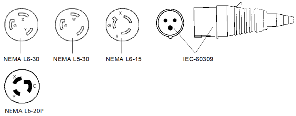
| North America | 110 | 20 | NEMA L5-20 | 20 |
| Internationalc | 240 | 16 | IEC 60309 | 20a or 16b |
| North America | 110 | 20 | NEMA L5-20 | 20 |
| North Americac | 208 | 20 | NEMA L6-20 | 20 |
| International | 240 | 16 | CEE 7/7 European Shunko | 16 |
|
a 20 amps in North America b 16 amps international c Default power cords that ship with modules |
||||
Electrical Specifications for Series 2 Modules
| Location | Voltage (Single Phase, 50-60 Hz) | Required Protective Service | Delivered Power Connectors | AMPs |
|---|---|---|---|---|
| North America | 110 | 30 | NEMA L5-30 | 30 |
| North Americac | 208 | 30 | NEMA L6-30 | 30 |
| North America | 208 | 20 | NEMA L6-20 | 20 |
| North America | 208 | 15 | NEMA L6-15 | 15 |
| Internationalc | 240 | 16 | IEC 60309 2P+E | 20a or 16b |
|
a 20 amps in North America b 16 amps international c Default power cords that ship with modules |
||||
Supported Power Connectors - HDEM and Series 3 Modules

Support Power Connectors - Series 2 Modules
| Environmental Factor | Recommended¹ | Allowed² | Shipping³ |
|---|---|---|---|
|
Dry-Bulb Temperature |
LTO-5, -6, -7. -8:
LTO-9, -10:
|
LTO-5, -6, -7. -8:
LTO-9, -10:
|
-23 to 49°C (-9 to 120°F) |
| Relative Humidity |
20 to 50% (non-condensing) |
20 to 80% (non-condensing) |
5 to 80% (non-condensing) |
| Maximum Temperature Change |
5° C per hour |
5° C per hour |
N/A |
| Maximum Humidity Change |
5% per hour |
5% per hour |
N/A |
| Temperature Limitation for Humidity Conditions |
LTO-5, -6, -7. -8:
LTO-9, -10:
|
LTO-5, -6, -7. -8:
LTO-9, -10:
|
Wet Bulb Temp <= 26°C (79°F) |
| Maximum Altitude |
3048 m (10000 ft) |
3048 m (10000 ft) |
12192 m (40000 ft). |
| Particulate Requirements |
Data centers should meet the cleanliness level of ISO 14644-1 class 8. For data centers without air-side economizers, the ISO 14644-1 class 8 cleanliness can be meet by choosing one of the following filtration methods:
For data centers with air-side economizers, the choice of filters to achieve ISO class 8 cleanliness depends on the specific conditions present at that data center. The deliquescent relative humidity of the particulate contamination must be more than 60% RH. Data centers must be free of zinc whiskers. For more information on ISO 14644-1 class 8, refer to the International Organization for Standardization (ISO) at https://www.iso.org. |
||
| Gaseous Contamination |
Severity level G1 as per ANSI/ISA 71.04-1985,¹ which states that the reactivity rate of copper coupons shall be less than 300 Angstroms per month (Å/month, ≈ 0.0039 µg/cm² - hour weight gain).² In addition, the reactivity rate of silver coupons shall be less than 300 Å/month (≈ 0.0035 µg/cm² - hour weight gain).³ The reactive monitoring of gaseous corrosivity should be conducted approximately 5 cm (2 inches) in front of the rack on the air inlet side at one-quarter and three-quarter frame height off the floor or where the air velocity is much higher. |
||
Definition of Terms:
¹ Recommended: The recommended operational/storage environmental envelope provides guidance on the environmental range for optimal performance and high reliability. This environmental range protects for 30-year archival storage. (Derate the maximum recommended dry-bulb temperature by 1°C/300 m above 1,800 m (1.8°F/1,000 feet above 6,000 feet)).
² Allowed: The allowable operational/storage environmental envelope defines the test limits to verify that the equipment will function within the environmental envelope. This environmental range is defined for operational storage of less than 6 months. (Derate the maximum dry-bulb temperature by 1°C/300 m above 900 m (1.8°F/1,000 feet above 3,000 feet)).
³ Shipping: When shipping media over extended environmental ranges, shipping times should be limited to minimize the duration of media being exposed to varying environmental conditions at lower and upper ranges.
Additional Information
-
The prolonged exposure to conditions outside the recommended range, especially approaching the extremes of the allowable operating environment, can result in decreased equipment reliability and longevity. An occasional short-term excursion into the allowable envelope is generally acceptable but may result in performance and reliability implications and higher power consumption. For additional information regarding tape cartridge storage, shipping and operational requirements, including acclimation requirements, please visit www.quantum.com/lto-media, or refer to specific LTO tape media specifications provided by the LTO consortium at www.lto.org or specifications provided by the media manufacturer.
-
Airflow on the Scalar i6000 is front to back.
The table below describes the port and network details for site-to-site firewall settings:
| Port | Protocol | Direction | TCP/UDP |
Description |
|---|---|---|---|---|
| 22 | SSH | Inbound | TCP | SSH access for CLI usage. Can disable SSH on the library. |
| 25 | SMTP | Outbound | TCP |
Email client. Can override this default port by putting the port on the back of the email host name. For example, |
| 53 | DNS | Outbound | UDP + TCP | DNS client model. |
|
67 68 |
DHCP | Outbound | UDP | DHCP client. |
| 80 | HTTP | Inbound | TCP | Library is a web server for administrative purposes. |
| 123 | NTP | Inbound/Outbound | UDP | NTP client |
| 161 | SNMP | Inbound/Outbound | UDP | SNMP queries and management. |
| 162 | SNMP | Outbound | UDP | Trap output. |
| 389 | LDAP | Outbound | TCP | Non-secure LDAP client. |
| 443 | HTTP | Inbound | TCP | Secure web server. |
| 636 | LDAPS | Outbond | TCP | Secure LDAP client. |
| 5696 | KMIP | Outbound | TCP | KMIP communication port on the server. Library uses non-priviledged ports. |
|
6000 6001 |
SKM | Outbound | TCP | SKM tape encryption protocol. |
Inventory time varies based on the number of modules and module type. The inventory times for each module are provided below:
- CM: 72 seconds
- DREM: 72 seconds
- SEM: 72 seconds
- HDEM (no scanner): 136 seconds
- HDEM (with scanner): 34 seconds
- LPM/RPM: 34 seconds
- Dual Robot feature generally reduces the inventory time by 50%.
Exchange performance is highly dependent on library configuration. Key performance factors include the number of modules, number of drives, placement of drives, use of HDEMs, and the number of partitions in the library. The library can be configured to meet specific robot performance. These configurations may require modules and other components that differ from standard configurations. Make sure any specific performance requirements are communicated prior to ordering the library and again prior to installation.
The Scalar i6000 is capable of performing up to 239 exchanges per hour with a single robot and single partition.
This section contains the physical specifications for all possible library configurations.
The maximum weight, distributed load, and point load figures provided in the sections below were calculated using the heaviest configurations for a given frame count. Where differences between Gen 1/Gen 2 or single robotics/dual robotics exist, the heaviest number was used.
Note: If the library is installed on a raised floor, the raised floor should be stabilized to prevent any horizontal movement. The library has four point loads each on the control and expansion modules.
The Scalar i6000 is a highly configurable library. Standard configuration rules are used for the placement of drives and modules. If specific configuration requirements are needed, e.g. placing drives in specific modules, then these requirements must be communicated before the library/upgrade order is placed so all the components needed to support the configuration are ordered and shipped. The standard configuration rules are listed below (orientation is based on facing the front of the library):
| Library Generation | Configuration | Modules |
|---|---|---|
| Gen 1 | Single Robot |
|
| Gen 2 | Single Robot |
|
| Gen 2 | Dual Robots |
|
| Gen 2 | Dual Robots with an HDEM |
|
| Library Generation | Configuration | Modules |
|---|---|---|
| Gen 1 | Single Robot |
|
| Gen 2 | Single Robot |
Note: HDEMs require Gen 2 electronics. |
| Gen 2 | Dual Robot |
Note: HDEMs require Gen 2 electronics. |
| Module | Library Location |
|---|---|
| Control Module | Location is always the first module on the left, except when Dual Robots are installed. When Dual Robots are installed, the CM is the second module from the left. |
| Expansion Modules | Drive Ready Expansion Module (DREM) are always installed to the right of the CM. If there are multiple DREMs to be installed, the order of the DREMS is a 72 slot I/E station is first, then a 24 slot I/E station and finally a DREM without an I/E station. High-Density Expansion Modules (HDEM) are placed after the CM and DREMs. If there are multiple HDEMs to be installed, the order of the HDEMS is a 72 slot I/E station is first, then a 24 slot I/E station and finally a HDEM without an I/E station. Storage Expansion Module (SEM) are placed after the CM, DREMs and HDEMs. If there are multiple SEMs to be installed, the order of the SEMS is a 72 slot I/E station is first, then a 24 slot I/E station and finally a SEM without an I/E station. Additional Modules added to existing systems are added to the right. One exception is if an HDEM or DREM3 is added to a Dual Robot library, in this case the HDEM or DREM3 is inserted to the left of the Right Parking Module. |
| Parking Modules |
Left Parking Module (LPM) is only used when Dual Robots are installed and is always located on the far left of the library. Note, the LPM is not ordered separately, it is shipped with the Dual Robot. Right Parking Module (RPM) is only used when Dual Robots are installed and is always located on the far right of the library. The RPM is a converted SEM or DREM. Note: An HDEM or DREM3 cannot function as a parking module. |
- The Control Module always ships with a 24 slot I/E station and there are no other options.
- Optional 24-slot I/E Station can be installed in any DREM, SEM, HDEM or RPM.
- Optional 72-slot can be installed in DREMs, HDEMs or SEMs, but not in the RPM.
- The LPM cannot support I/E Stations.
- A maximum of 16 I/E stations (including the CM I/E Station) can be installed in a library, but with the restrictions listed above.
- I/E Stations are installed left to right, with the 72-slot I/E Stations installed closest to the CM followed by 24-slot I/E Stations.
- The library supports a maximum of 192 tape drives.
- Tape drives are only installed in CMs and DREMs.
- SEMs, HDEMs and the LPM do not support tape drives, but SEMs can be converted to DREMs for drive support. Note that DREMs can only be used as a RPM in a Dual Robot library if they do not have the full compliment of 24 drives.
- A maximum of 18 drives can be installed in each control module and a DREM can contain a maximum of 24 drives.
- While drives can be installed in any module configured to accept them, it is recommended that they are installed left to right, with the first drives installed in the CM and moving to the next DREM to the right.
- The default power cords are sent with each CM, DREM and HDEM. If redundant power is ordered, an extra cord is sent. If any of the optional power cords are needed, they must be ordered.
The table below provides specifications for the common building blocks to help you calculate your specific configuration.
Details Specific to Single-Robot Configuration
Fully loaded: robot, drives, redundant power, 24-slot I/E, media
| Weight | Point Load | Height | Width | Depth |
|---|---|---|---|---|
|
899 lb 409 kg |
71.5 lb/in. 5.0 kg/cm |
77.4 in 196.6 cm |
24.3 in 61.7 cm |
38.3 in 97.3 cm |
Details Specific to Dual-Robot Configuration
Fully loaded: robot, drives, redundant power, 24-slot I/E, media
| Weight | Point Load | Height | Width | Depth |
|---|---|---|---|---|
|
897 lb 408 kg |
71.4 lb/in. 5.0 kg/cm |
77.4 in 196.6 cm |
24.3 in 61.7 cm |
38.3 in 97.3 cm |
Fully loaded: drives, redundant power supplies, 24-slot I/E, and media.
| Weight | Point Load | Height | Width | Depth |
|---|---|---|---|---|
|
623 lb 283 kg |
49.6 lb/in. 3.5 kg/cm |
77.4 in 196.6 cm |
23.6 in 59.9 cm |
38.3 in 97.3 cm |
Media only
| Weight | Point Load | Height | Width | Depth |
|---|---|---|---|---|
|
723 lb 339 kg |
78.3 lb/in. 5.5 kg/cm |
77.4 in 196.6 cm |
23.6 in 59.9 cm |
38.3 in 97.3 cm |
Fully loaded: drives, redundant power supplies, 24-slot I/E, and media.
| Weight | Point Load | Height | Width | Depth |
|---|---|---|---|---|
|
820 lb 373 kg |
65.2 lb/in. 4.6 kg/cm |
77.4 in 196.6 cm |
23.6 in 59.9 cm |
38.3 in 97.3 cm |
Fully loaded with LTO media.
| Weight | Point Load | Height | Width | Depth |
|---|---|---|---|---|
|
985 lb 448 kg |
78.3 lb/in. 5.5 kg/cm |
77.4 in 196.6 cm |
23.6 in 59.9 cm |
38.3 in 97.3 cm |
Details Common to Both Configurations
Empty SEMS
| Weight | Point Load | Height | Width | Depth |
|---|---|---|---|---|
|
586 lb 266 kg |
46.6 lb/in. 3.3 kg/cm |
77.4 in 196.6 cm |
23.6 in 59.9 cm |
38.3 in 97.3 cm |
Media Only
| Weight | Point Load | Height | Width | Depth |
|---|---|---|---|---|
|
820 lb 373 kg |
65.2 lb/in. 4.5 kg/cm |
77.4 in 196.6 cm |
23.6 in 59.9 cm |
38.3 in 97.3 cm |
Fully loaded: drives, redundant power, and media.
| Weight | Point Load | Height | Width | Depth |
|---|---|---|---|---|
|
882 lb 401 kg |
70.2 lb/in. 4.9 kg/cm |
77.4 in 196.6 cm |
23.6 in 59.9 cm |
38.3 in 97.3 cm |
Fully loaded: drives, redundant power, 24-slot I/E, and media.
| Weight | Point Load | Height | Width | Depth |
|---|---|---|---|---|
|
882 lb 401 kg |
70.2 lb/in. 4.9 kg/cm |
77.4 in 196.6 cm |
23.6 in 59.9 cm |
38.3 in 97.3 cm |
Fully loaded: drives, redundant power, 72-slot I/E, and media.
| Weight | Point Load | Height | Width | Depth |
|---|---|---|---|---|
|
894 lb 406 kg |
71.1 lb/in. 5.0 kg/cm |
77.4 in 196.6 cm |
23.6 in 59.9 cm |
38.3 in 97.3 cm |
Empty
| Weight | Point Load | Height | Width | Depth |
|---|---|---|---|---|
|
627 lb 284 kg |
49.6 lb/in. 3.5 kg/cm |
77.4 in 196.6 cm |
23.6 in 59.9 cm |
38.3 in 97.3 cm |
Fully loaded with LTO media.
| Weight | Point Load | Height | Width | Depth |
|---|---|---|---|---|
|
994 lb 451 kg |
78.3 lb/in. 6.5 kg/cm |
77.4 in 196.6 cm |
23.6 in 59.9 cm |
38.3 in 97.3 cm |
Full loaded: redundant power, media, 24-slot I/E
| Weight | Point Load | Height | Width | Depth |
|---|---|---|---|---|
|
977 lb 443 kg |
80.3 lb/in. 5.6 kg/cm |
77.4 in 196.6 cm |
23.6 in 59.9 cm |
38.3 in 97.3 cm |
Full loaded: redundant power, media, 72-slot I/E
| Weight | Point Load | Height | Width | Depth |
|---|---|---|---|---|
|
949 lb 430 kg |
78.0 lb/in. 5.5 kg/cm |
77.4 in 196.6 cm |
23.6 in 59.9 cm |
38.3 in 97.3 cm |
The smallest library configuration consists of the control module only. The minimal configuration contains one I/E station and one drive.
Note: This configuration applies to single-robot systems only.
The maximum Gen 1 library configuration is 12 frames and the maximum Gen 2 library configuration is 20 frames. The maximum Gen 1 and Gen 2 single-robotics configurations are shown in Figure 29 and Figure 30.
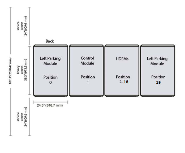
The smallest dual-robotics library configuration is a three-frame system. It consists of one control module, a left parking module, and a right parking module. The minimum with an HDEM is a four-frame system since an HDEM cannot be a parking module.
Note: This configuration is only available for a dual-robot setup.
The maximum library configuration is 20 frames. A dual-robotics seventeen frame configuration consists of the control module, left parking module, right parking module, and 17 expansion modules. The maximum dual-robotics configurations are shown below.
Note: 24.3” (61.7 cm) is Quantum’s minimum physical clearance requirement. Consult local building code enforcement agency to determine your building’s minimum working space.
Figure 1: Gen 1 Single-Robot Configuration
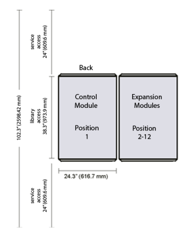
Figure 2: Gen 2 Single-Robot Configuration
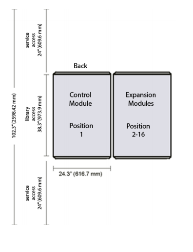
Figure 3: Dual-Robot Configuration
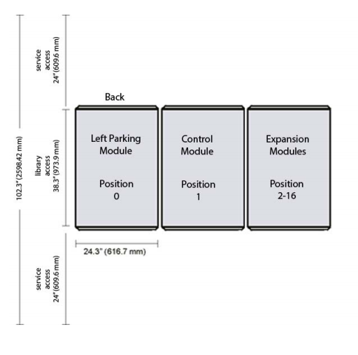
Figure 4: Dual-Robot HDEM Configuration
The library control modules, expansion modules, and parking modules are each shipped on the same type of specially designed pallet. For dual-robot new installs or upgrades, the robots will be shipped inside the module.
The pallet’s dimensions are listed below.
| Height | Width | Length |
|---|---|---|
| 87 in. (221.0 cm) | 42.5 in. (108.0 cm) | 48 in. (121.9 cm) |
The library foot pad positions looking down from the top are show in the figure below. The foot pad positions are the same for the control module, expansion modules, HDEMs and parking modules.
Figure 5: Library Module Foot Pad Positions
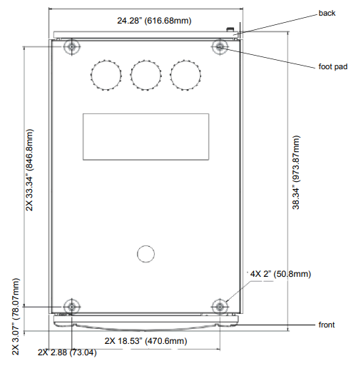
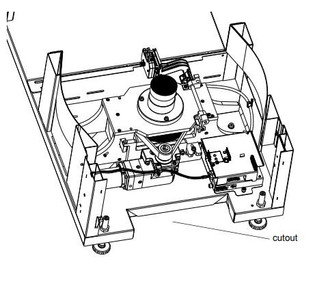
The foot pad positions are shown from underneath the library in Figure 6. The module floor cutouts are the same for the control module, expansion modules, and parking modules. However, the HDEM has a different module floor cutout, as seen in Figure 8 and Figure 9.
Note: Floor cutouts can be used for cable access as well as the access hole at the top of the module.
Figure 6: Module Floor Cutout (Bottom View)
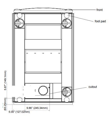
Figure 7: Module Floor Cutout (Front View)
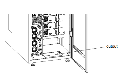
Figure 8: HDEM Floor Cutout (Front View)
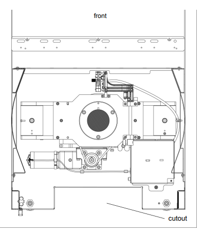
Figure 9: HDEM Floor Cutout (Bottom View)
The tape drives are enclosed in a universal drive sled. The library supports the following tape drives types:
- IBM LTO-1 or LTO-2 LVD–SCSI
- IBM LTO-1, LTO-2, LTO-3, LTO-4, LTO-5, LTO-6, LTO-7, LTO-8, LTO-9, and LTO-10 FC Multi-mode
- IBM LTO-9 and LTO-10 SAS
- HP LTO-3, HP LTO-4, LTO-5, and LTO-6 FC Multi-mode
For i11 and above, the control module and the drive ready expansion modules have two sets of upper and lower drive clusters. Each library must have at least one tape drive. Each drive cluster can house up to six tape drives for a total of 24 drives per module. While additional drives can be added to any DREM in the configuration, the maximum number of drives is 192. In dual robotics systems, the left parking module cannot contain drives.
Even though tape drives can be installed in any module (except LPM and HDEM), it is recommended that tape drives be installed in bottom-to-top order in the control module before any are added to other expansion modules. Once the control module has 18 drives installed from bottom to top, you should move to bottom drive position of a drive-ready expansion module.
Additional Information
- Library firmware versions 630Q (i10) and later do not support DLT tape drives, media, or magazines. If you upgrade to these library firmware versions, make arrangements to remove and/or replace all DLT tape drives, media, and magazines in your library. If you want to continue to use DLT tape drives and media, your library firmware must be at version 617G.GS01001 (i8.4) or earlier.
- Standard expansion modules in positions 9 through 16 are no longer storage-only expansion modules.
- The term drive cluster defines a grouping of up to six tape drives below or above the middle X-axis rail.
-
When you add drives, you lose storage slots.
-
The Scalar i6000 library configured with tape drives over Native Fibre Channel connectivity, allows the utilization of all tape drives simultaneously without loss of performance when utilizing direct connectivity of the Tape Drives with Customer SAN Fabric and Backup Servers environment. The compatibility matrix between LTO tape drives, Scalar Tape Libraries and SAN Switches can be found at http://www.quantum.com/swcompguide.aspx.
The control module and any drive ready expansion module (including the right parking module in dual-robot configurations) can each contain up to 12 FC linear tape-open format tape drives (LTO-1, LTO-2, LTO-3, LTO-4, LTO-5, LTO-6, LTO-7, LTO-8, LTO-9, and LTO-10).
Although all seven generations of LTO drives are supported in the library, the drives are not fully compatible (both read/write).
|
LTO-4 | LTO-4 WORM |
LTO-5 | LTO-5 WORM |
LTO-6 | LTO-6 WORM |
LTO-7 | LTO-7 WORM |
||
|---|---|---|---|---|---|---|---|---|---|---|
| LTO-4 Drives |
Reads/ Writes | Write Once, Read Many | N/C | N/C | N/C | N/C | N/C | N/C | ||
| LTO-5 Drives | Reads/ Writes |
Write Once, Read Many | Reads/ Writes |
Write Once, Read Many | N/C | N/C | N/C | N/C | ||
| LTO-6 Drives | Reads | Reads | Reads/ Writes |
Write Once, Read Many | Read / Writes |
Write Once, Read Many | N/C | N/C | ||
| LTO-7 Drives | N/C | N/C | Reads | Reads | Reads/ Writes |
Write Once, Read Many | Reads/ Writes |
Write Once, Read Many | ||
| LTO-8 Drives | N/C | N/C | N/C | N/C | N/C | N/C | Reads/ Writes |
Write Once, Read Many | ||
| LTO-9 Drives | N/C | N/C | N/C | N/C | N/C | N/C | N/C | N/C | ||
| LTO-10 Drives | N/C | N/C | N/C | N/C | N/C | N/C | N/C | N/C |
|
LTO-8 | LTO-8 WORM |
LTO-8 M8 | LTO-9 | LTO-9 WORM | LTO-10 | LTO-10 WORM | ||
|---|---|---|---|---|---|---|---|---|---|
| LTO-4 Drives | N/C | N/C | N/C | N/C | N/C | N/C | N/C | ||
| LTO-5 Drives | N/C | N/C | N/C | N/C | N/C | N/C | N/C | ||
| LTO-6 Drives | N/C | N/C | N/C | N/C | N/C | N/C | N/C | ||
| LTO-7 Drives | N/C | N/C | N/C | N/C | N/C | N/C | N/C | ||
| LTO-8 Drives | Reads/ Writes |
Write Once, Read Many | Reads/ Writes |
N/C | N/C | N/C | N/C | ||
| LTO-9 Drives | Reads/ Writes |
Write Once, Read Many | N/C | Reads/ Writes |
Write Once, Read Many | N/C | N/C | ||
| LTO-10 Drives | N/C | N/C | N/C | N/C | N/C | Reads/ Writes |
Write Once, Read Many |
All LTO cartridges are the same size, which means they use the same magazines in the library. LTO drives can be directly attached to hosts, attached to the storage area network (SAN), or connected to FC I/O blades in the I/O management unit.
LTO-8 introduces a new media formatting option, the M format. The M format is used with LTO-8 tape drives and LTO-7 media. When LTO-7 media is M formatted by an LTO-8 tape drive, the data capacity of the LTO-7 media is 9TB native, compared to 6TB of a standard formatted LTO-7 tape.
Type M Media Format Requirements
Scalar i6000 systems have the following requirements when using M format media:
- A new bar code media identifier is used with M formatted LTO-7 tapes.
- The media must be new, not previously used.
- The media must have a bar code label that contains the media identifier M8.
- The last two characters of the bar code are M8.
The Scalar i6000 library supports WORM (write once, read many) technology in LTO-3, LTO-4, LTO-5, LTO-6, LTO-7, LTO-8, LTO-9, and LTO-10 tape drives. WORM requirements include:
- Cartridges
- Firmware
- WORM-supported LTO-4 tape drives
- WORM-supported LTO-5 tape drives
- WORM-supported LTO-6 tape drives
- WORM-supported LTO-7 tape drives
- WORM-supported LTO-8 tape drives
- WORM-supported LTO-9 tape drives
- WORM-supported LTO-10 tape drives
WORM allows non-erasable data to be written once and provides extra data security by prohibiting accidental data erasure. When the library firmware and WORM-supported LTO-4 or later tape drive code are installed on a library with LTO-4 or later tape drives, the WORM feature is supported whenever the operator uses WORM cartridges.
The magazine is a storage assembly that installs on the drive side or door side of the control module, expansion module, or parking module. It contains the cartridge slots and provides flexibility when adding storage cartridges to a module. The LTO magazines hold six cartridges. Magazines are removable and may have moved during shipment; make sure they are seated.
| Type | Magazine Capacity | Cartridge Capacity |
|---|---|---|
| Magazine (LTO) | N/A | 6 |
| Control Module (single-robotics)a | 36 min 51 max |
216 min 306 max |
| Control Module (dual-robotics)a | 42 min 64 max |
252 min 384 max |
| Standard Expansion Modulec | 48 min 76 max |
288 min 456 max |
| Drive Ready Expansion Moduleb | 16 min 76 max |
96 min 456 max |
| High-Density Expansion Modulec | 102 min 130 max |
612 min 780 max |
| Left Parking Module (dual-robotics)d | 38 | 228 |
| Right Parking Module (dual-robotics)e | 12 min 38 max |
72 min 228 max |
|
a Control module: The minimum is based on having 18 drives and one 24-slot I/E station installed. The maximum is based on having one drive and one 24-slot I/E station installed. b Drive Ready Expansion module: The minimum is based on having 24 drives and one 72-slot I/E station and 24 drives installed. The maximum is based on having no drives or an I/E station installed. c Standard and HDEM: The minimum is based on one 72-slot I/E station and 12 drives installed. The maximum is based on having no drives or an I/E station installed. d Left parking module: No drives or I/E stations are allowed. The left parking space takes up 4 columns of storage. There are six empty magazines located in the unusable 4 columns which are used for calibration only. These six magazines are not counted toward the total capacity. e Right parking module: The minimum is based on having 12 drives and one 24-slot I/E station installed. The maximum is based on no drives or I/E station installed. The right parking space takes up 4 columns of storage. |
||
Each magazine has a barcode label that the scanner reads for identification and inventory. An optional, snap-on dust cover is available for the magazines to be used for external storage. The magazines with the dust cover have interlocked stacking that enables easier storage of the media when they are removed from the library.
Site Preparations
All servers or appliances intended to communicate with the Scalar i6000 robotic controller or tape drives must be already installed on the SAN before configuring the library for fiber channel SAN connectivity. Additionally, the World Wide Names (WWNs) of the associated fiber channel HBAs should be visible on the SAN. This is necessary because the Scalar i6000 “Extended Virtual Private SAN” (eVPS) feature can only grant LUN access to WWNs it discovers on the SAN at the time of configuration.
To configure a tape drive for either control path or data path failover, you need the following:
- The library must have a Native Storage Networking license installed.
- The tape drive to be configured for data path failover must be licensed for native storage networking.
- The tape drive must be an HP LTO-5 or LTO-6 Fibre Channel tape drive.
- The tape drive must be connected to an Ethernet Expansion Blade (EEB) via an Ethernet cable. The minimum number of EEBs are included with the Native Storage Networking license. Additional EEBs may be purchased if desired.
- Both tape drive fibre ports MUST be connected to switches that are part of the same fabric. For example, Fabric A to Fabric B failover is NOT supported.
- Switch fabric zoning strategy MUST use the WWPN strategy.
- Both FC ports on the tape drive must be connected to an NPIV-supported switch, and both switch ports MUST have N-Port Virtualization (NPIV) enabled. Neither tape drive port may be connected to a host or Fibre Channel I/O blade.
- Quantum recommends making sure your switches are at the latest firmware version to ensure stable N-Port Virtualization (NPIV) functioning.
- The tape drive topology settings must be set to Point to Point.
- HP LTO-5 and LTO-6 FC tape drive firmware must be at the version qualified with the Scalar i6000 library. See the Scalar i6000 Release Notes for qualified firmware levels.
If you are upgrading your library from a single robot system to a dual robot system (whether from Gen 1 or Gen 2), please understand and address the following requirements before Service arrives to do the upgrade:
| Requirement |
|---|
| Scalar i6000 — Scalar i2000 libraries must be upgraded to Scalar i6000 before upgrading to dual robotics. |
| Gen 2 — Dual robotics libraries use the Gen 2 robot. If you are upgrading from a Gen 1 system, the hardware and robots need to be upgraded to Gen 2. You cannot add a second robot to a Gen 1 system. |
| No DLT tape drives, media, or magazines — Dual robotics libraries do not support DLT tape drives or media. Remove these from the library before the upgrade. |
|
Sufficient physical space — The dual robotics library upgrade requires a left parking module to be installed to the left of the control module. Make sure you have sufficient space for the additional module. If this will require moving the library, ensure the new space is prepared, ready, and level prior to the upgrade. Note: The minimum dual-robot configuration consists of three modules (left parking module, control module, and right parking module). |
| No 72-slot I/E station in right-most module — The right-most module of a dual-robotics system cannot have a 72-slot I/E station. If your current right-most expansion module contains a 72-slot I/E station, notify your Sales representative so that an additional module can shipped and installed on the right end of the system. (If you do not have space for an additional module, then Service will swap your right-most module with an existing module in the library that does not contain a 72-slot I/E station.) |
If you are upgrading a Gen 1 library to a Gen 2 single-robotics library, please understand and address the following requirements before Service arrives to do the upgrade:
| Requirement |
|---|
| Scalar i6000 — Scalar i2000 libraries must be upgraded to Scalar i6000 before upgrading to Gen 2 robotics. |
| No DLT tape drives, media, or magazines — Gen 2 robotics libraries do not support DLT tape drives or media. Remove these from the library before the upgrade. |
| Requirement |
|---|
| Scalar i6000 — Scalar i6000 libraries must be upgraded to i11 before an HDEM can be added. |
| The Scalar i6000 library must contain a Gen 2 Robotics and Electronics Kit to support an HDEM. |


