DXi9100 Capacity Upgrade
This topic provides instructions for upgrading the storage capacity in Quantum DXi9100 disk backup systems. The storage capacity of the system is determined by two factors:
- Physical Storage Capacity is determined by the number of DXi9000/DXi9100 HD Array Modules (RBODs) and Expansion Modules (EBODs) installed in the system. Each module provides 720 TB of raw unformatted storage capacity (60 x 12 TB), up to a system maximum of 2880 TB, using 2 Array Modules and 2 Expansion Modules.
- Licensed Storage Capacity is the amount of storage capacity the customer is allowed to access and use. Each Array Module (RBOD) and Expansion Module (EBOD) can be licensed for 510 TB of usable storage capacity, up to a system maximum of 2040 TB, or 2 PB.
The physical storage capacity of the system can be greater than the licensed capacity. DXi9100 storage capacity is licensed in 102 TB increments. To purchase a storage capacity upgrade license, contact Quantum Customer Support.
Note: DXi9000 HD and DXi9100 systems use DXi9000/DXi9100 HD Array Modules (RBODs) and Expansion Modules (EBODs). The number of array and expansion modules is determined by your configuration.
|
Configuration |
Licensed Usable Capacity1, 2 (TB)3 | System Memory (GB) | 4U60 Array Modules (RBODs) | 4U60 Expansion Modules (EBODs) | Total Rack Space Required |
|---|---|---|---|---|---|
|
204 | 1536 |
1 |
0 | 6U |
| 306 | 1536 | 1 | 0 | 6U | |
| 408 | 1536 | 1 | 0 | 6U | |
| 510 | 1536 | 1 | 0 | 6U | |
| 612 | 1536 | 2 | 0 | 10U | |
| 714 | 1536 | 2 | 0 | 10U | |
| 816 | 1536 | 2 | 0 | 10U | |
| 918 | 1536 | 2 | 0 | 10U | |
| 1020 | 1536 | 2 | 0 | 10U | |
| 1122 | 1536 | 2 | 1 | 14U | |
| 1224 | 1536 | 2 | 1 | 14U | |
| 1326 | 1536 | 2 | 1 | 14U | |
| 1428 | 1536 | 2 | 1 | 14U | |
| 1530 | 1536 | 2 | 1 | 14U | |
| 1632 | 1536 | 2 | 2 | 18U | |
| 1734 | 1536 | 2 | 2 | 18U | |
| 1836 | 1536 | 2 | 2 | 18U | |
| 1938 | 1536 | 2 | 2 | 18U | |
| 2040 | 1536 | 2 | 2 |
18U |
|
| 4Quantum recommends installing the dual port 100 GbE card in slots 1,4, and 8. If those slots are already used by existing 100 GbE cards, then use slot 7 for your fourth 100 GbE card. Slots 8, 4, and 1 have 16 PCIe lanes and slot 7 is has 8 PCIe lanes. | |||||
Make sure the following conditions are met before you continue with the capacity upgrade:
- All backup jobs are completed and there is no pending I/O.
- All replication jobs are completed, and replication is paused (Replication > Actions page).
- All space reclamation tasks are completed without errors (Utilities > Space Reclamation page).
- All healthchecks are completed without errors (Utilities > Space Reclamation page).
- All components in the system display Normal status (Status > Hardware page).
- All outstanding administration alerts are deleted (Alerts > Admin Alerts page).
- All service tickets are closed (Alerts > Service Tickets page).
Note: For more information, click Help in the remote management console to display the DXi online help.
To access the remote management console, do the following:
-
Launch a supported Web browser on a workstation that has network access to the DXi9100.
The DXi GUI is compatible with Chromium-based web browsers. Quantum-tested Chromium-based browsers include Brave, Google Chrome, Microsoft Edge, Opera and Vivaldi. Mozilla Firefox is also compatible with the GUI.
-
In the browser address box, type the IP address of the DXi9100, and then press <Enter>.
The Login window displays.

If the Login window does not display, verify that the IP address is correct and that the network path to the DXi9100 is valid. Also verify that you are using a supported Web browser. Then try again. If you are still unable to access the Login window, contact the DXi GUI administrator.
-
Select the Service login type and enter the corresponding password.
Note: Contact the DXi system GUI Administrator for the Service password.
- Click Login.
-
If a security banner message has been specified for the DXi9100, click Accept.
The Home page displays.

The following tools are required for unpacking and installing the DXi9000 Series system:
- #2 Phillips screwdriver
- Small flat head screwdriver
- Notebook computer
Some components within the DXi9100 system contain static-sensitive parts. To avoid damaging these parts while performing installation procedures, always observe the following precautions:
- Keep the DXi9100 system (including all Node, Array and Expansion Modules if part of your configuration) turned off during all installation procedures.
- Keep static-sensitive parts in their original shipping containers until ready for installation.
- Do not place static-sensitive parts on a metal surface. Place them inside their protective shipping bag or on an antistatic mat.
- Wear anti-static wrist bands when unpacking and handling the units, and avoid touching connectors and other components.
Note: Dry climates and cold-weather heating environments have lower relative humidity and are more likely to produce static electricity.
Capacity Upgrade Overview
To upgrade the storage capacity for an installed Array Module (RBOD) or Expansion Module (EBOD), you must enter the new storage capacity license key. Skip directly to Installing the Storage Capacity License.
Note: DXi9000 HD and DXi9100 systems use DXi9000/DXi9100 HD Array Modules (RBODs) and Expansion Modules (EBODs). The number of array and expansion modules is determined by your configuration.
Tasks
The base DXi9100 system is comprised of one Node and one Array Module (RBOD). To add and upgrade the storage capacity of the DXi9100 by adding a second Array Module (RBOD) or a second Array Module, then 1 or 2 Expansion Modules (EBODs), complete the following major steps in order:
- Shut Down the System
- Unpack the Array Module and Expansion Module(s)
- Install the Array or Expansion Module
- Install the Array and Expansion Drives
- Add the New Storage to the System
- Installing the Storage Capacity License
Note: Each Array Module (RBOD) and Expansion Module (EBOD) can be licensed for 510 TB of usable storage capacity, up to a system maximum of 2040 TB, or 2 PB. For DXi9100 system configurations, see DXi9100 Supported Configurations.
Review and document the current system configuration before you continue with the capacity upgrade.
- Current physical disk capacity (Home page).
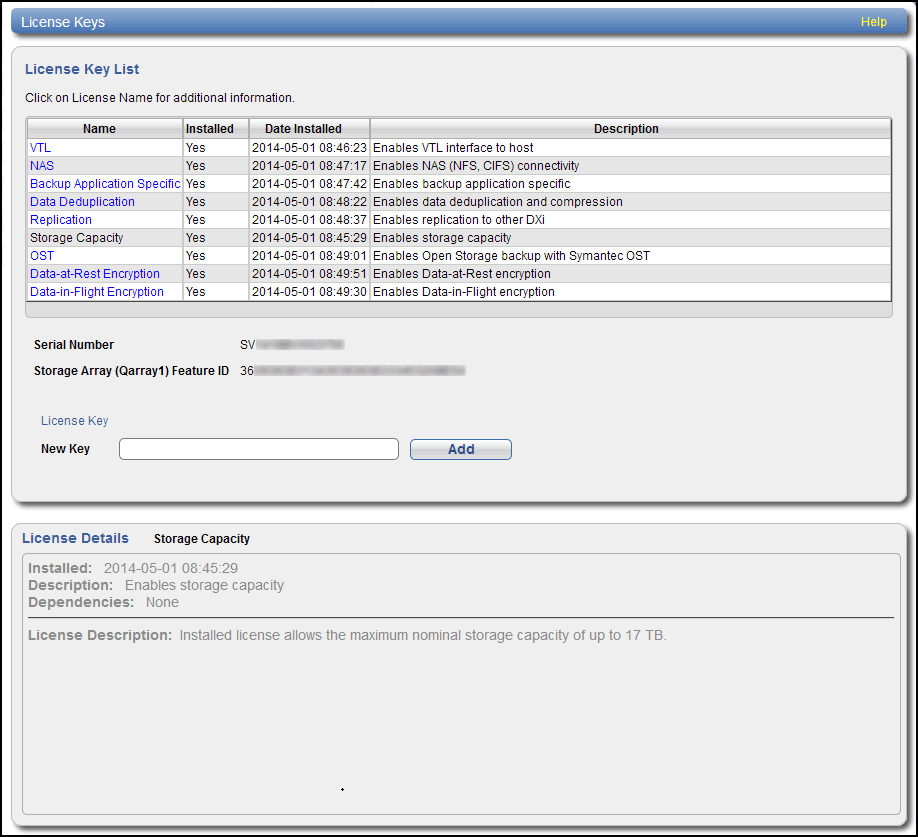
- Current licensed disk capacity (Utilities > License Keys page).
Before adding an Array Module or Expansion Module(s), you must shut down the DXi9100.
Important - Generate and Download System Logs
Generate and download the latest version of the following system logs before shutting down the system. this will provide a record of the system prior to any hardware configuration changes.
- Utilities > Diagnostics > System Diag File
- Utilities > Diagnostics > Storage Array Diag File
-
Shut down the system from the remote management console using the Shutdown option on the Utilities > Reboot & Shutdown page.
Note: Shutting down the system can take up to 30 minutes. Only the Node will completely shut down.
-
After the Node shuts down, turn off both power switches on the back of the Expansion Module and Array Module(s) as applicable for your existing system configuration. For DXi9100 system configurations, see DXi9100 Supported Configurations.
Wait until the seven segment display on the rear of the module turns off.
Array Module (RBOD) Power Switches
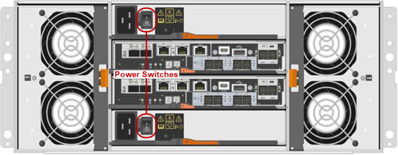
Note: This image shows a quad-port SAS HIC (Host Interface Card). New Array Modules (RBODs) will arrive with a dual-port SAS HIC.
-
Document the seven segment display on each Expansion Module (EBOD 1-1 is 00, etc.). Turn off both power switches on the back of each Expansion Module (EBOD).
Expansion Module (EBOD) Power Switches

Note: DXi9000 HD and DXi9100 systems use DXi9000/DXi9100 HD Array Modules (RBODs) and Expansion Modules (EBODs). The number of array and expansion modules is determined by your configuration.
Carefully unpack and remove the Array Module and/or Expansion Module(s), as well as all accessories, from the packing materials.
The box containing the DXi9000 Series Array Module or Expansion Module contains the following items. MAKE SURE YOU HAVE ALL THE ITEMS BELOW BEFORE YOU BEGIN THE UPGRADE.
Carefully unpack and remove the components from the packing materials.
Caution: Make sure to retain all packing materials, as well as the documentation and other items included in the shipping box. The packaging materials must be used if the system is relocated.
WARNING: The DXi9000/DXi9100 HD Array module and Expansion module (empty) each weigh 132.0 pounds (60.0 kg). A minimum of two people are required to lift the chassis.
Carefully unpack and remove the components from the packing materials.

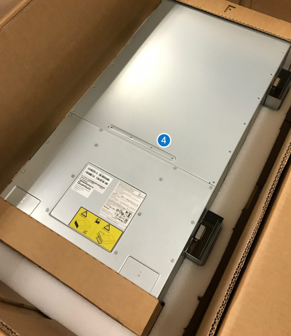
| Item | Description |
|---|---|
| 1 | Rack Rails |
| 2 | Accessory Kit |
| 3 | Bezel (required for EMI shielding) |
| 4 | Array or Expansion Module |
WARNING: Do not install the drives until after the module has been installed in the rack. Each Array Module and Expansion Module weighs 250 pounds (113 kg) when fully configured with all drives.
The box containing the DXi9000/DXi9100 HD Array module (RBOD) or Expansion module (EBOD) contains the following items:
| Item | Description |
|---|---|
| Accessory kit |
Includes the following:
|
| Rack Rails | Includes screws and spacers. |
All necessary license certificates are contained in the upgrade kit:
- Capacity Upgrade License Certificate - A single license is included to enable the total storage capacity of the system after the upgrade.
Tasks
Installing the DXi9000 Series Expansion Modules in a rack consists of the following steps:
Component Installation Recommendations
To make it easier to correctly cable the system, and for safety reasons, follow these recommendations when installing the DXi9100 system in the rack:
- A rack is not included with the DXi9100. A standard 40U rack can be ordered from Quantum as an optional purchase.
- Make sure to leave enough space in the rack for future system expansion. The DXi9100 can be expanded to a maximum configuration requiring 18U of rack space.
Recommended DXi9000 Series Component Rack Order (Maximum Configuration)

The DXi9000 Series system is designed to fit in a standard 19 inch (48.3 cm) wide rack. It is important for the chassis installation to locate the hole pattern in the rack rails. You must allow 4U (6.8 inches or 17.4 cm) of vertical space for the DXi9000 Series Node and an additional 4U for each Array module (RBOD) and Expansion module (EBOD) installed in the rack.
Rack cabinets that meet EIA-310 standards have an alternating pattern of three holes per rack unit with center-to-center hole spacing (beginning at the top hole of a 1U space) of 15.9 mm, 15.9 mm, and 12.7 mm (0.625 inch, 0.625 inch, and 0.5 inch) for the front and back vertical rails. Rack cabinets may have round or square holes. For more information, refer to DXi9000 Series Site Planning.
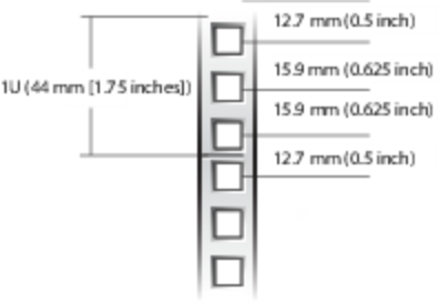
WARNING: If the rack is empty at the time of installation, do NOT install the DXi9000 Series chassis too high in the rack. The weight of the chassis may cause the rack to become “top heavy” and unstable if installed in the top of an empty rack.
To mark the rack, place a mark (or tape) on the rack’s front vertical rails where you want to locate the bottom of the unit you are installing in the rack. The bottom of each 1U space is at the middle of the narrowest metal strip between holes (marked with a horizontal line on some rack cabinets).
- Position the left and right rail end pieces labeled FRONT facing inward, and orient each end piece to seat in the holes on the front side of the vertical rack flanges.
- Align each back end piece in the bottom and top holes of the desired U spaces.
- Engage the back end of the rail until it fully seats on the vertical rack flange and the latch clicks into place. Repeat these actions to position and seat the front end piece on the vertical rack flange.
- Using the screws provided, bolt the rails to the rack on both the front and back.
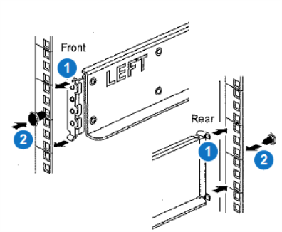
| Item | Description |
|---|---|
| 1 | Latches click into place in rack flange (round or square holes). |
| 2 | Screws |
WARNING: The DXi9000/DXi9100 HD Array module and Expansion module (empty) each weigh 132.0 pounds (60.0 kg). A minimum of two people are required to lift the chassis.
- If you are using a mechanized lift, you do not need the module handles. If you are lifting and moving the module by hand, attach the four handles. Push up on each handle until it clicks into place.
- Place the back of the module (the end with the connectors) on the rails.
- Supporting the module from the bottom, slide it into the cabinet. If you are using the handles, use the thumb latches to detach the handles as you slide the module in.
- Using the provided screws and PEM nuts, secure the module to the front of the rack by inserting two screws in the 1st and 3rd holes (counting down from the top) on each side.
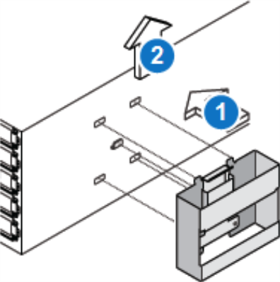
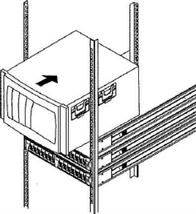
Secure Module to the Rack

Follow these steps to cable the DXi9100:
The following subsections illustrate cabling for the DXi9100 Node, Array Module(s), and Expansion Module(s), based on the storage capacity range for each configuration.
This configuration shows cabling for 204 TB - 510 TB storage capacity systems: Node + Array Module.
Note: The quad-port 1 GbE card in slot 5 is manufactured with port numbering.
| Node | Array Module | |
|---|---|---|
| Connect PCI Slot 2 - Port 0 | → | Controller A - SAS Ch 0c |
| Connect PCI Slot 3 - Port 0 | → |
Controller B - SAS Ch 0c |
| Connect Slot 5 - Port 1 | → | Controller A - Ethernet Management Port 1 |
| Connect Slot 5 - Port 2 | → | Controller B - Ethernet Management Port 1 |

Note: This image shows a quad-port SAS HIC (Host Interface Card). New Array Modules (RBODs) will arrive with a dual-port SAS HIC. The image above and example image below both show the connection from the Node to the quad-port HIC's far-left port, labeled 0c. If your Array Module has the dual-port card installed, the far-left 0c port is still used to connect from the Node.
Example: Array Controller SAS Port Ch 0c

This configuration shows cabling for 204 TB - 510 TB storage capacity systems: Node + 1 Array Module.
Note: The quad-port 1 GbE card in slot 5 is manufactured with port numbering.
| Node | Array Module | |
|---|---|---|
| Connect PCI Slot 2 - Port 1 (second from right) | → | Controller A - SAS Ch 0c |
| Connect PCI Slot 3 - Port 1 (second from right) | → |
Controller B - SAS Ch 0c |
| Connect Slot 5 - Port 1 | → | Controller A - Ethernet Management Port 1 |
| Connect Slot 5 - Port 2 | → | Controller B - Ethernet Management Port 1 |
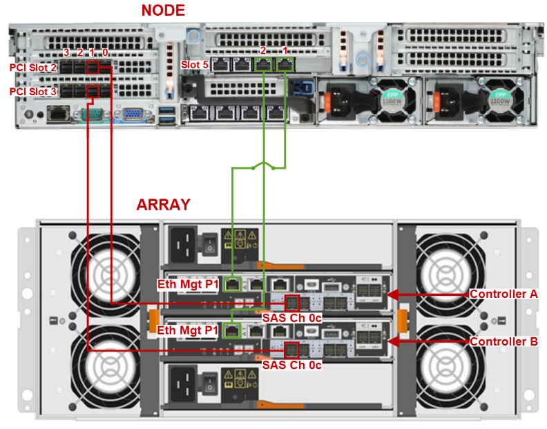
Note: This image shows a quad-port SAS HIC (Host Interface Card). New Array Modules (RBODs) will arrive with a dual-port SAS HIC. The image above shows the connection from the Node to the quad-port HIC's far-left port, labeled 0c. If your Array Module has the dual-port card installed, the far-left 0c port is still used to connect from the Node.
This configuration shows cabling for 612 TB - 1020 TB storage capacity systems: Node + 2 Array Modules.
| Node | Array Modules | |
|---|---|---|
| Connect PCI Slot 2 - Port 0 | → | Array 1 Controller A - SAS Ch 0c |
| Connect PCI Slot 3 - Port 0 | → | Array 1 Controller B - SAS Ch 0c |
| Connect PCI Slot 2 - Port 1 | → | Array 2 Controller A - SAS Ch 0c |
| Connect PCI Slot 3 - Port 1 | → | Array 2 Controller B - SAS Ch 0c |
| Connect Slot 5 - Port 1 | → | Array 1 Controller A - Ethernet Management Port 1 |
| Connect Slot 5 - Port 2 | → | Array 1 Controller B - Ethernet Management Port 1 |
| Connect Slot 5 - Port 3 | → | Array 2 Controller A - Ethernet Management Port 1 |
| Connect Slot 5 - Port 4 | → | Array 2 Controller B - Ethernet Management Port 1 |
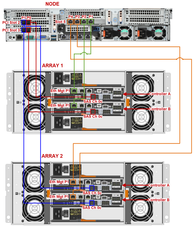
Note: This image shows a quad-port SAS HIC (Host Interface Card). New Array Modules (RBODs) will arrive with a dual-port SAS HIC. The image above and example image below both show the connection from the Node to the quad-port HIC's far-left port, labeled 0c. If your Array Module has the dual-port card installed, the far-left 0c port is still used to connect from the Node.
Example: Array Controller SAS Port Ch 0c

This configuration shows cabling for 612 TB - 1020 TB storage capacity systems: Node + 2 Array Modules.
| Node | Array Modules | |
|---|---|---|
| Connect PCI Slot 2 - Port 0 (far-right port) | → | Array 2 Controller A - SAS Ch 0c |
| Connect PCI Slot 3 - Port 0 (far-right port) | → | Array 2 Controller B - SAS Ch 0c |
| Connect PCI Slot 2 - Port 1 (second from right) | → | Array 1 Controller A - SAS Ch 0c |
| Connect PCI Slot 3 - Port 1 (second from right) | → | Array 1 Controller B - SAS Ch 0c |
| Connect Slot 5 - Port 1 | → | Array 1 Controller A - Ethernet Management Port 1 |
| Connect Slot 5 - Port 2 | → | Array 1 Controller B - Ethernet Management Port 1 |
| Connect Slot 5 - Port 3 | → | Array 2 Controller A - Ethernet Management Port 1 |
| Connect Slot 5 - Port 4 | → | Array 2 Controller B - Ethernet Management Port 1 |
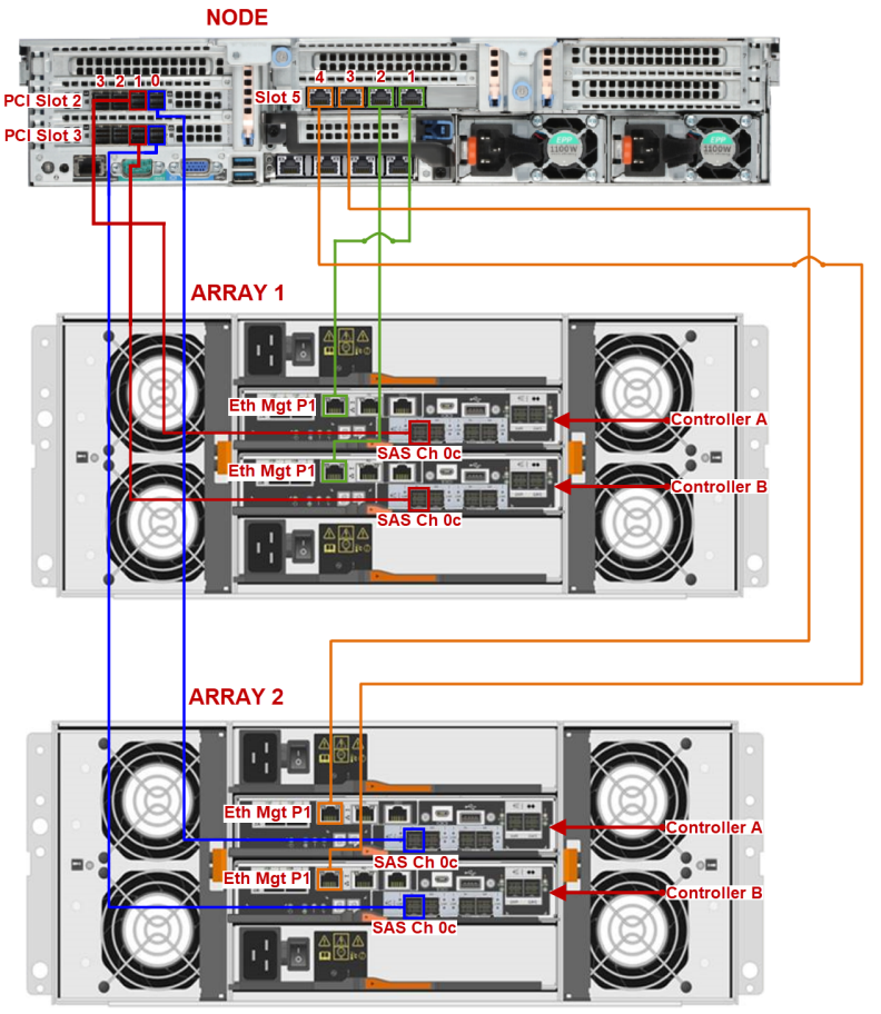
Note: This image shows a quad-port SAS HIC (Host Interface Card). New Array Modules (RBODs) will arrive with a dual-port SAS HIC. The image above and example image below both show the connection from the Node to the quad-port HIC's far-left port, labeled 0c. If your Array Module has the dual-port card installed, the far-left 0c port is still used to connect from the Node.
Example: Array Controller SAS Port Ch 0c

Cabling DXi9100 Systems Containing 1 or 2 Expansion Modules
Cabling from the DXi9100 Node to the first Array in this configuration is the same as for:
-
DXi9100 Cabling: Node + 2 Array Modules + Expansion Module
The above configuration is used in systems configured for 1122 TB - 1530 TB storage capacity. -
DXi9100 Cabling: Node + 2 Array Modules + 2 Expansion Modules
The above configuration is used in systems configured for 1622 TB - 2040 TB (2 PB) storage capacity.
This configuration shows cabling for 1122 TB - 1530 TB storage capacity systems: Node + 2 Array Modules + 1 Expansion Module.
| Node | Array Modules | Expansion Module | ||
|---|---|---|---|---|
| Connect PCI Slot 2 - Port 0 | → | Array 1 Controller A - SAS Ch 0c | ||
| Connect PCI Slot 3 - Port 0 | → | Array 1 Controller B - SAS Ch 0c | ||
| Connect PCI Slot 2 - Port 1 | → | Array 2 Controller A - SAS Ch 0c | ||
| Connect PCI Slot 3 - Port 1 | → | Array 2 Controller B - SAS Ch 0c | ||
| Connect Slot 5 - Port 1 | → | Array 1 Controller A - Ethernet Management Port 1 | ||
| Connect Slot 5 - Port 2 | → | Array 1 Controller B - Ethernet Management Port 1 | ||
| Connect Slot 5 - Port 3 | → | Array 2 Controller A - Ethernet Management Port 1 | ||
| Connect Slot 5 - Port 4 | → | Array 2 Controller B - Ethernet Management Port 1 | ||
| Array 1 Controller A - SAS Drive Expansion Port EXP1 | → | Expansion IOM A - SAS Host Connector Port 1 | ||
| Array 1 Controller B - SAS Drive Expansion Port EXP1 | → | Expansion IOM B - SAS Host Connector Port 1 |
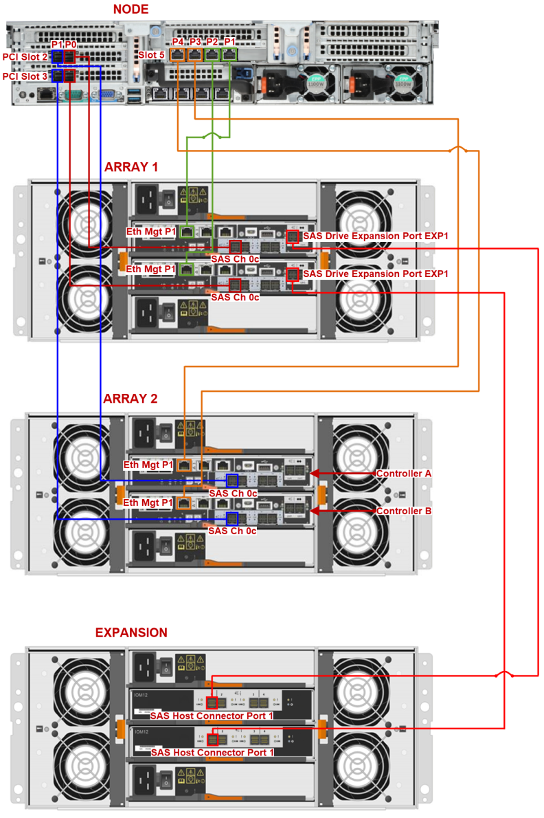
Note: This image shows a quad-port SAS HIC (Host Interface Card). New Array Modules (RBODs) will arrive with a dual-port SAS HIC. The image above and example image below both show the connection from the Node to the quad-port HIC's far-left port, labeled 0c. If your Array Module has the dual-port card installed, the far-left 0c port is still used to connect from the Node.
Example: Array Controller SAS Port Ch 0c

Cabling DXi9100 Systems Containing 1 or 2 Expansion Modules
Cabling from the DXi9100 Node to the first Array in this configuration is the same as for:
-
DXi9100 Cabling: Node + 2 Array Modules + Expansion Module
The above configuration is used in systems configured for 1122 TB - 1530 TB storage capacity. -
DXi9100 Cabling: Node + 2 Array Modules + 2 Expansion Modules
The above configuration is used in systems configured for 1622 TB - 2040 TB (2 PB) storage capacity.
This configuration shows cabling for 1622 TB - 2040 TB (2 PB) storage capacity systems: Node + 2 Array Modules + 1 Expansion Module.
| Node | Array Modules | Expansion Module | ||
|---|---|---|---|---|
| Connect PCI Slot 2 - Port 0 | → | Array 1 Controller A - SAS Ch 0c | ||
| Connect PCI Slot 3 - Port 0 | → | Array 1 Controller B - SAS Ch 0c | ||
| Connect PCI Slot 2 - Port 1 | → | Array 2 Controller A - SAS Ch 0c | ||
| Connect PCI Slot 3 - Port 1 | → | Array 2 Controller B - SAS Ch 0c | ||
| Connect Slot 5 - Port 1 | → | Array 1 Controller A - Ethernet Management Port 1 | ||
| Connect Slot 5 - Port 2 | → | Array 1 Controller B - Ethernet Management Port 1 | ||
| Connect Slot 5 - Port 3 | → | Array 2 Controller A - Ethernet Management Port 1 | ||
| Connect Slot 5 - Port 4 | → | Array 2 Controller B - Ethernet Management Port 1 | ||
| Array 1 Controller A - SAS Drive Expansion Port EXP1 | → | Expansion 1 IOM A - SAS Host Connector Port 1 | ||
| Array 1 Controller B - SAS Drive Expansion Port EXP1 | → | Expansion 1 IOM B - SAS Host Connector Port 1 | ||
| Array 2 Controller A - SAS Drive Expansion Port EXP1 | → | Expansion 2 IOM A - SAS Host Connector Port 1 | ||
| Array 2 Controller B - SAS Drive Expansion Port EXP1 | → | Expansion 2 IOM B - SAS Host Connector Port 1 |

Note: This image shows a quad-port SAS HIC (Host Interface Card). New Array Modules (RBODs) will arrive with a dual-port SAS HIC. The image above and example image below both show the connection from the Node to the quad-port HIC's far-left port, labeled 0c. If your Array Module has the dual-port card installed, the far-left 0c port is still used to connect from the Node.
Example: Array Controller SAS Port Ch 0c

Cabling DXi9100 Systems Containing 1 or 2 Expansion Modules
Cabling from the DXi9100 Node to the first Array in this configuration is the same as for:
-
DXi9100 Cabling: Node + 2 Array Modules + Expansion Module
The above configuration is used in systems configured for 1122 TB - 1530 TB storage capacity. -
DXi9100 Cabling: Node + 2 Array Modules + 2 Expansion Modules
The above configuration is used in systems configured for 1622 TB - 2040 TB (2 PB) storage capacity.
For systems using Fibre Channel (FC) cabling, connect FC cables to each FC port. If there is a port cover on the port, remove it before connecting a cable.
Fibre Channel Cabling

| Item | Description |
|---|---|
| 1 | To PTT or VTL (optional) |
| 2 | To PTT or VTL (optional) |
| 3 | To PTT or VTL (optional) |
| 4 | To PTT or VTL (optional) |
Connect each power supply to a primary and secondary AC power source using the provided power cables. Use the attached straps to secure the power cords to the chassis.
Important Information
Quantum recommends connecting each power cord to a separate AC circuit to ensure system availability in case of a power failure. Power supplies should be checked periodically for audible and LED warnings.
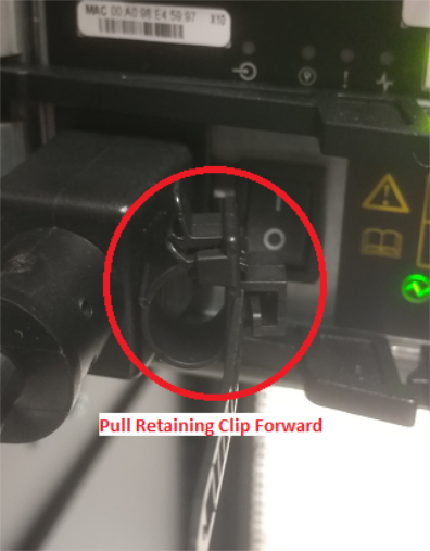
Warning - Power Cord Retaining Clip
The power cord retaining clip can block full insertion of the power cord connector. Pull the clip forward before attempting to connect the power cord.
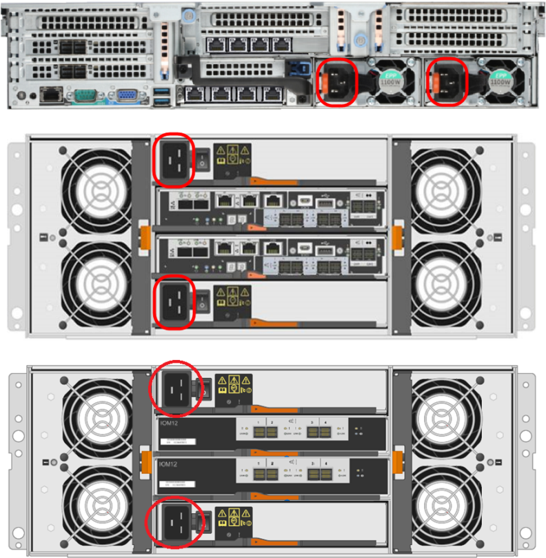
Note: After all cables are attached, move each cable to the left and right, then gently pull straight out to confirm that the cable is locked.
WARNING: If cables are not secure when connected to the modules, the software may not recognize all hardware at startup.
Ethernet Cables
Do not connect any Ethernet cables at this time. (You will connect them in a later procedure.)
Note: DXi9000 HD and DXi9100 systems use DXi9000/DXi9100 HD Array Modules (RBODs) and Expansion Modules (EBODs). The number of array and expansion modules is determined by your configuration.
A DXi9100 capacity upgrade requires adding additional 3.5 inch 12 TB hard disk drives (HDDs) to the DXi9000/DXi9100 HD Array and Expansion modules. The number of HDDs to be installed ranges from 24 (204 TB system) up to 120 (1020 TB system).
WARNING: Do not install the drives until after the DXi9000/DXi9100 HD Array (RBOD) and Expansion (EBOD) module has been installed in the rack. Each module weighs 250 pounds (113 kg) when fully configured with all drives.
Each module contains five drive drawers, with each drawer labeled 1 - 5.
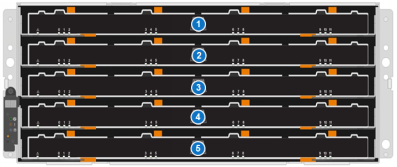
| Item | Drawer |
|---|---|
| 1 | Drawer 1 |
| 2 | Drawer 2 |
| 3 | Drawer 3 |
| 4 | Drawer 4 |
| 5 | Drawer 6 |
Each drawer can hold 12 drives in 3 rows. The drive locations are numbered 0 - 11.
Array and Expansion Module Drive Drawer - Drive Locations

| Item | Drawer Drive Location |
|---|---|
| 1 | Front Row (Drives 0,3,6,9) |
| 2 | Middle Row (Drives 1,4,7,10) |
| 3 | Back Row (Drive 2,5,8,11) |
The number of drives to be installed depends on the capacity of the system.
Use the following chart to find your system's capacity and the number of drives to install. Then use the Array and Expansion Module Drive Installation Locations chart to determine drive placement.
| Capacity (TB) | Hardware Configuration | Node | Array Module (RBOD)1 | Drives in Server |
1GbE Cables2 | Expansion Module (EBOD)1 | Array or Expansion Drives3 | Capacity License (TB)4 |
| 204 (Base system) |
Node + 1 RBOD | 1 | 1 | 13 | 2 cables (1 pair) | 0 | 24 | 204 |
| 306 | Node + 1 RBOD | 1 | 1 | 13 | 2 cables (1 pair) | 0 | 36 | (+102=) 306 |
| 408 | Node + 1 RBOD | 1 | 1 | 13 | 2 cables (1 pair) | 0 | 48 | (+102=) 408 |
| 510 | Node + 1 RBOD | 1 | 1 | 13 | 2 cables (1 pair) | 0 | 60 | (+102=) 510 |
| 612 |
Node + 2 RBODs |
1 | 2 | 13 | 4 cables (2 pair) | 0 | 84 | (+102=) 612 |
| 714 | Node + 2 RBODs | 1 | 2 | 13 | 4 cables (2 pair) | 0 | 84 | (+102=) 714 |
| 816 | Node + 2 RBODs | 1 | 2 | 13 | 4 cables (2 pair) | 0 | 96 | (+102=) |
| 918 | Node + 2 RBODs | 1 | 2 | 13 | 4 cables (2 pair) | 0 | 108 | (+102=) 918 |
| 1020 | Node + 2 RBODs | 1 | 2 | 13 | 4 cables (2 pair) | 0 | 120 | (+102=) 1020 |
| 1122 | Node + 2 RBODs + 1 EBOD | 1 | 2 | 13 | 4 cables (2 pair) | 1 | 144 | (+102=) 1122 |
| 1224 | Node + 2 RBODs + 1 EBOD | 1 | 2 | 13 | 4 cables (2 pair) | 1 | 144 | (+102=) 1224 |
| 1326 | Node + 2 RBODs + 1 EBOD | 1 | 2 | 13 | 4 cables (2 pair) | 1 | 156 | (+102=) 1326 |
| 1428 | Node + 2 RBODs + 1 EBOD | 1 | 2 | 13 | 4 cables (2 pair) | 1 | 168 | (+102=) 1428 |
| 1530 | Node + 2 RBODs + 1 EBOD | 1 | 2 | 13 | 4 cables (2 pair) | 1 | 180 | (+102=) 1530 |
| 1632 | Node + 2 RBODs + 2 EBODs | 1 | 2 | 13 | 4 cables (2 pair) | 2 | 204 | (+102=) 1632 |
| 1734 | Node + 2 RBODs + 2 EBODs | 1 | 2 | 13 | 4 cables (2 pair) | 2 | 204 | (+102=) 1734 |
| 1836 | Node + 2 RBODs + 2 EBODs | 1 | 2 | 13 | 4 cables (2 pair) | 2 | 216 | (+102=) 1836 |
| 1938 | Node + 2 RBODs + 2 EBODs | 1 | 2 | 13 | 4 cables (2 pair) | 2 | 228 | (+102=) 1938 |
| 2040 (Max system) |
Node + 2 RBODs + 2 EBODs | 1 | 2 | 13 | 4 cables (2 pair) | 2 | 240 | (+102=) 2040 |
|
14U60, factory installed 22 cables (1 pair), factory installed. 3Array and Expansion Module drives are 12 TB HDD (FDE or non-FDE). Base system includes 24 RBOD drives, shipped separately. 4Each capacity upgrade requires the purchase of a license, in 102 TB increments. |
||||||||
Install all 60 drives in the Array Module (RBOD), then install the drives in the EBOD using the chart below.
| Number of Array and Expansion Module Drives | RBOD and EBOD Drive Install Locations |
|---|---|
| 24 |
Drawer 1
Drawer 2 - Front Row (Drives 0,3,6,9) Drawer 3 - Front Row (Drives 0,3,6,9) Drawer 4 - Front Row (Drives 0,3,6,9) Drawer 5 - Front Row (Drives 0,3,6,9) |
| 36 |
Drawer 1 - All Rows (Drives 0 - 11) Drawer 2 - All Rows (Drives 0 - 11) Drawer 3 - Front Row (Drives 0,3,6,9) Drawer 4 - Front Row (Drives 0,3,6,9) Drawer 5 - Front Row (Drives 0,3,6,9) |
| 48 |
Drawer 1 - All Rows (Drives 0 - 11) Drawer 2 - All Rows (Drives 0 - 11) Drawer 3 - All Rows (Drives 0 - 11) Drawer 4
Drawer 5 - Front Row (Drives 0,3,6,9) |
| 60 |
Drawer 1 - All Rows (Drives 0 - 11) Drawer 2 - All Rows (Drives 0 - 11) Drawer 3 - All Rows (Drives 0 - 11) Drawer 4 - All Rows (Drives 0 - 11) Drawer 5 - All Rows (Drives 0 - 11) |
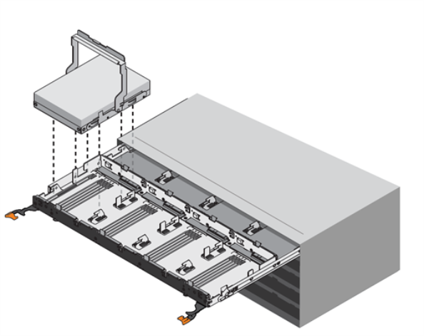
Follow these steps to add HDDs to the Array Module (RBOD) and Expansion Module (EBOD).
- Release the levers on the drive drawer.
- Using the levers, slide the drawer out.
- Raise the handle on the drive to vertical.
- Align the two raised buttons on the drive with the notches on the drawer. Then, pressing gently on the top of the drive, rotate the drive handle down until the drive snaps into place.
- Install the remaining drives.
- Slide the drawer back in by sliding it from the center and closing both levers gently.
-
Attach the bezel to the front of the RBOD and EBOD. The bezel is required for EMI shielding.
DXi9000/DXi9100 HD Array and Expansion Module Bezel

Array and Expansion Module Drive Installation
To make the storage capacity available to the DXi9100, you must add the new Expansion Modules (EBODs) to the system and initialize them.
IMPORTANT - READ BEFORE CONTINUING
- The Array module (RBOD) on the system prior to expansion must be licensed for maximum capacity before adding an additional Array Module and Expansion Module(s) (EBODs).
- Make sure all Array and Expansion module(s) are correctly cabled before you power on the system. See Cable the System for cabling diagrams for all configurations.
- Refer to the table below for the expansion order.
DXi9100 Array and Expansion Module Capacity Upgrade Order
| Expansion Order | DXi9100 Configuration |
|---|---|
| Base System | Node + RBOD |
| 1 | Node + 2 RBODs |
| 2 | Node + 2 RBODs + 1 EBOD |
| 3 | Node + 2 RBODs + 2 EBODs |
To add new storage to the system:
-
Power on the DXi9100 system components in the following order:
- If your system has an Expansion Module (EBOD), turn on both power switches on the back of the module. Wait until the seven segment display on the rear of the module displays 00.
- Turn on both power switches on the back of the Array Module(s) (RBODs). Wait until the seven segment display on the rear of the module(s) display 99 (approximately 5 minutes).
- Check that all drives are correctly seated in all enclosures before powering on the node.
- After powering on the system, do not remove any hard drives. If you accidentally remove a drive, wait 30 seconds before reinserting the drive.
- Press the power button on the front of the Node. Wait for the system to boot before continuing with the procedure. (This can take up to 10 minutes.)
Additional Information
Powering on the Expansion Modules

Powering on the Array Modules

Powering on the Node

- Using a terminal emulation program that supports SSH (like PuTTY), connect to the Node with the system IP address. You may not see prompt until the node has been power on for 5 to 10 minutes.
- Enter ServiceLogin for the user name and then enter the service password. Contact the system administrator for the service password.
- At the command prompt, type the following command and press Enter:
- At the command prompt, type the following command and press Enter:
- To access the Storage Expansion menu, type the following at the command prompt and press Enter:
The command prompt displays.
sudo -i
This command creates a shell with root access.
sh /opt/DXi/scripts/service.sh
The Service Menu displays.
Hardware Configuration >> Setup Storage >>> Expand Storage
The Service Expand Storage Menu displays.
- Type
0(the number option for RAID Initialize all Storage) and press.Enter. - After the system reboots, enter ServiceLogin for the user name and then enter the service password.
- At the command prompt, type the following command and press Enter:
- At the command prompt, type the following command and press Enter:
- To access the Storage Expansion menu, type the following at the command prompt and press Enter:
- Type
1(the number option for Expand Stornext filesystem) and press.Enter.
*** Service Expand Storage Menu ***
0) RAID Initialize all Storage - Look at all storage, RAID Initialize as needed.
1) Expand Stornext filesystem - Add new LUNs/Volumes to the DXi filesystem.
2) Expand Storage with (0) RAID Initialize, reboot, then (1) Expand Stornext
The system will examine all attached storage and start a RAID initialization in the background for every set of 12 drives that are not yet used. It will automatically reboot once the RAID initialization is started for all new storage.
sudo -i
sh /opt/DXi/scripts/service.sh
The Service Menu displays.
Hardware Configuration >> Setup Storage >>> Expand Storage
The Service Expand Storage Menu displays.
*** Service Expand Storage Menu ***
0) RAID Initialize all Storage - Look at all storage, RAID Initialize as needed.
1) Expand Stornext filesystem - Add new LUNs/Volumes to the DXi filesystem.
2) Expand Storage with (0) RAID Initialize, reboot, then (1) Expand Stornext
The system will find all LUNs and add them to the Stornext filesystem.
Once completed, it will reboot again.
After the system reboots, your DXi should display Normal.
Note: This process may take 30+ minutes.
Continue to Installing the Storage Capacity License.
Before the newly installed Expansion Modules (EBODs) can be used to store data, you must add a license key to enable the new total storage capacity of the system.
Locate the Storage Capacity License Certificate that was included in the upgrade kit, and then complete the following procedure:
-
Open two Web browser windows on a computer with Internet access.
Note: During this procedure, you can copy and paste required numbers between these two windows.
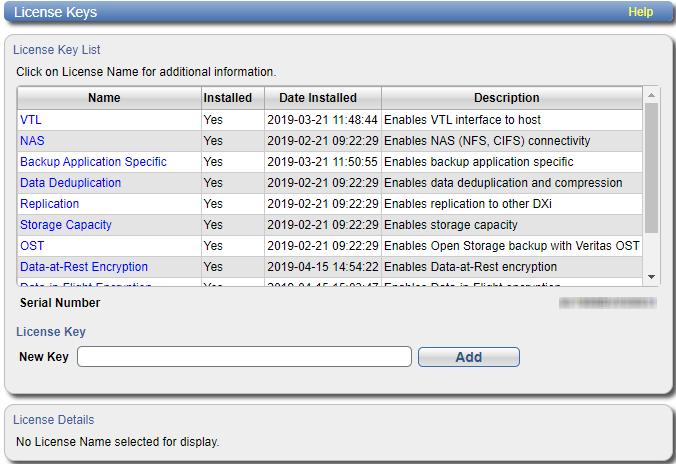
- In one browser, navigate to the Utilities > License Keys page in the DXi remote management console. Note that the system serial number displays directly above the New Key box.
- In the other browser, enter the address for the License Key Management Web site:
For information about accessing the remote management console, see the DXi9000 Series User’s Guide.
http://www.quantum.com/licensekeys

- On the License Key Management Web site, perform the following steps:
- Enter the system serial number in the Serial Number box and click Submit.
- Enter the authorization code (printed on the License Certificate) and click Get License Key.
- Switch to the Utilities > License Keys page in the DXi remote management console.
- Enter the license key in the New Key box and click Add.
- Click the Storage Capacity license link on the License Keys page. The maximum allowed storage capacity appears under License Details.
The Licensed Feature page returns a storage capacity key.
The file system is automatically expanded. (This can take up to 10 minutes.)
Verify that the correct total license storage is displayed.
