DXi4800 Node Front Panel Features and Indicators
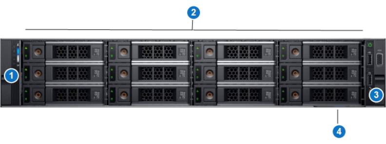
The controls, indicators, and connectors are located behind the optional rack bezel on the front panel of the DXi4800 Node.
DXi4800 Node - Front View

DXi4800 Node - Front Panel LED Indicators, Buttons, and Connectors
| Item | Indicator, Button, or Connector | Description |
|---|---|---|
| 1 | Left control panel |
Contains system health and system ID, and status LEDs. See DXi4800 Node - Left Control Panel for more information. Note: The diagnostic indicators display error statuses during system startup. |
| 2 | Hard disk drives (HDDs) | Six or twelve 3.5 inch hot-swappable hard drives (4 TB each). |
| 3 | Right control panel | Contains the power button, VGA port, iDRAC Direct micro USB port and two USB 2.0 ports. See DXi4800 Node - Right Control Panel for more information. |
| 4 | Information tag | A slide-out label panel which displays the system serial number. |
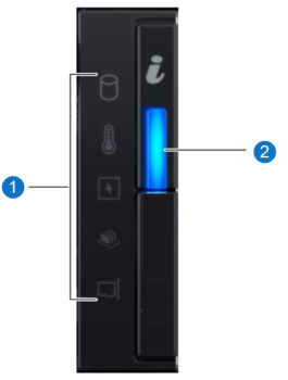
DXi4800 Node - Left Control Panel

DXi4800 Node - Left Control Panel Indicators
| Item | Indicator, Button, or Connector | Description |
|---|---|---|
| 1 | Status LED Indications |
The diagnostic indicators light up to display error statuses. For a description of possible statuses, see the table below. Note: The diagnostic indicators display error statuses during system startup. |
| 2 | System Health and System ID Indication |
Indicates the system health. Solid blue - The system is on and in good health. Blinking amber - The system is on and an error exists. If an error exists, see General Troubleshooting . |
DXi4800 Node - Status LED Indicators
|
Indicator |
Icon |
Condition |
Recommended Action |
| Hard Drive |
|
Blinking amber - A hard drive error has occurred | See Hardware Problems. |
| Temperature |
|
Blinking amber - A thermal error has occurred. | See Temperature Problems. |
| Electrical |
|
Blinking amber - An electrical error has occurred. | See Hardware Problems |
| Memory |
|
Blinking amber - A memory error has occurred. | See General Troubleshooting . |
| PCIe |
|
Blinking amber - A PCIe card error has occurred. | See General Troubleshooting . |
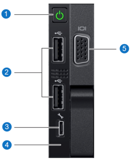
DXi4800 Node - Right Control Panel

DXi4800 Node - Right Control Panel Indicators
| Item | Indicator, Button, or Connector | Description |
|---|---|---|
| 1 | Power-on indicator, power button |
The power-on indicator lights when the system power is on. The power button controls the power supply output to the system. WARNING: Turning off the power removes the main power but keeps standby power supplied to the Node. Because of this, you must unplug the Node before servicing. Caution: Turning off the power without properly shutting down the system may result in loss of data. Note: To shut down the Node in the event of an emergency, press and hold the power button for 4 seconds. Warning: This may result in data loss and may cause a delay on next startup due to a blockpool verify operation. |
| 2 | USB 2.0 connectors |
Caution: Use of connected peripheral devices, such as a USB keyboard and mouse or a VGA display, is not supported and may cause incorrect system operation. |
| 3 | iDRAC port | For Quantum service use only. |
| 4 | iDRAC LED | For Quantum service use only. |
| 5 | VGA port |
Caution: Use of connected peripheral devices, such as a USB keyboard and mouse or a VGA display, is not supported and may cause incorrect system operation. |
