Install

|
How to Create a PDF |
Note: Refer to these warnings (in different languages) at: Safety Information
Caution: Electrostatic Discharge (ESD) can damage electronic components. To prevent such damage to PCBs (printed circuit boards), it is important to use a grounded wrist strap, handle all PCBs by their edges and keep them in anti-static bags when not in use.
Observe the following industry standard warnings:
- Warn the user of situations which have the potential for bodily injury.
- Should you have questions or experience difficulty, refer to Contacting Quantum for assistance.
- Only certified technicians should attempt to install or configure the system components.
Identify a suitable location for the system.
- The area should be clean, dust-free area that is well ventilated.
- Avoid areas where heat, electrical noise and electromagnetic fields are generated.
-
Leave enough clearance to allow sufficient space for airflow and access when servicing the system.
- In front of the rack: allow enough space to open the front door completely (~25 inches).
- In the back of the rack: allow approximately 30 inches of clearance.
- The system:
- Should be installed only in a Restricted Access Location (dedicated equipment rooms, service closets, etc.).
Is not suitable for use with visual display workplace devices.
- The system requires a grounded AC power outlet.
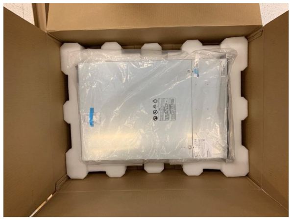
- Inspect the system shipping container. Check for any damage on the top, bottom, and sides of the box.
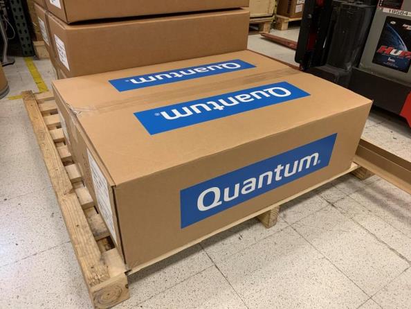
- Remove the system hardware from the shipping container.
Note: Remove the Quick Start Guide from the container.
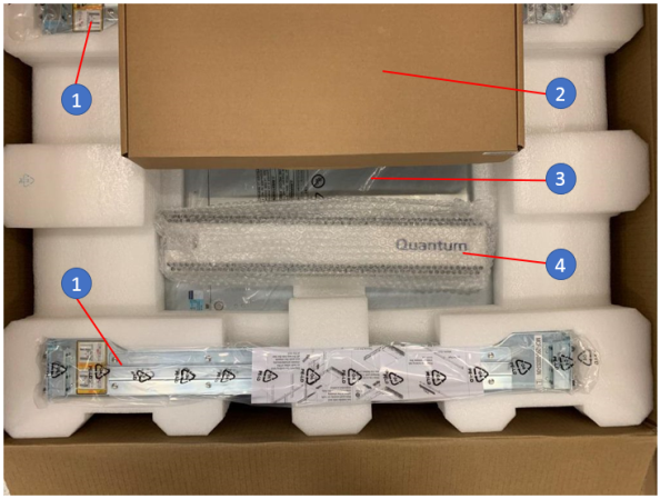
Item Description 1 Chassis Rails (left & right) 2 Installation Hardware (cables, screws) 3 NVR System (under installation hardware box) 4 Bezel Note: Also remove the mouse and keyboard from the shipping container. - Remove the system from the container and inspect for any damage (top, bottom, and sides).
If the system appears damaged, file a damage claim with the carrier who delivered the system.
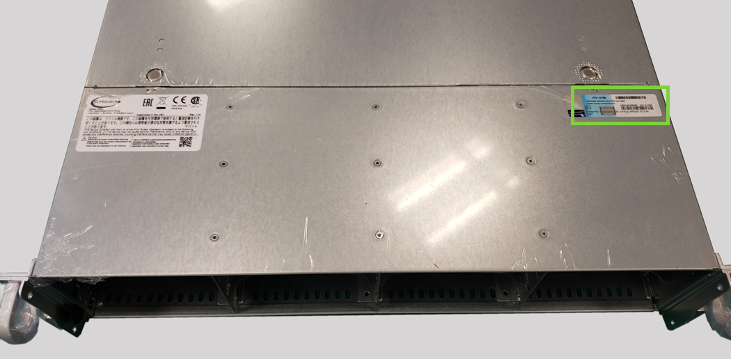
Pro Tip!
Note the Windows Product Key (location shown below). Write this down or take a picture of the key to use when you Register Windows 10 during the Windows configuration steps done after the hardware installation. This is especially important if the system is located in the rack where other hardware components are installed above this system.

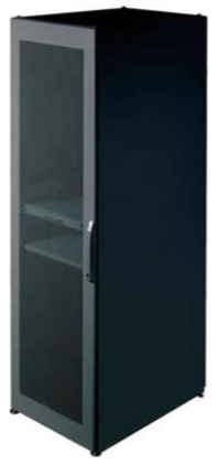
There are a variety of cabinets (rack units) on the market, which may require a slightly different assembly procedure.
- The following is a basic guideline for installing the system into a:
- Standard cabinet (4-post rack unit)
- Telco Rack (2-post rack unit)
- Refer to the installation instructions that came with the specific cabinet (rack unit) you are using.
- The rails and the related hardware should have been included with the system.
Note: Determine where you want to place the server in the cabinet. Normally heavier units are installed at the bottom of the cabinet for stability.
WARNING: Stability hazard. The cabinet stabilizing mechanism must be in place, or the cabinet must be bolted to the floor before you slide the unit out for servicing. Failure to stabilize the cabinet can cause the cabinet to tip over.
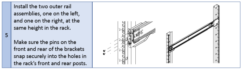
Note: Use screws to secure the front and back of the outer rails onto the rack.
WARNING: Due to its weight and to prevent potential tip-over, Quantum recommends installing the server as low as possible in an empty cabinet.
Note: Optional screws may be used to secure the chassis to the rack.
-
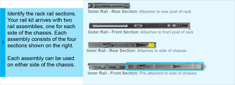
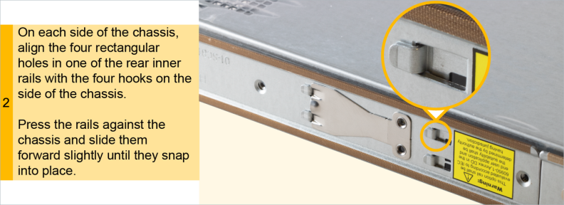
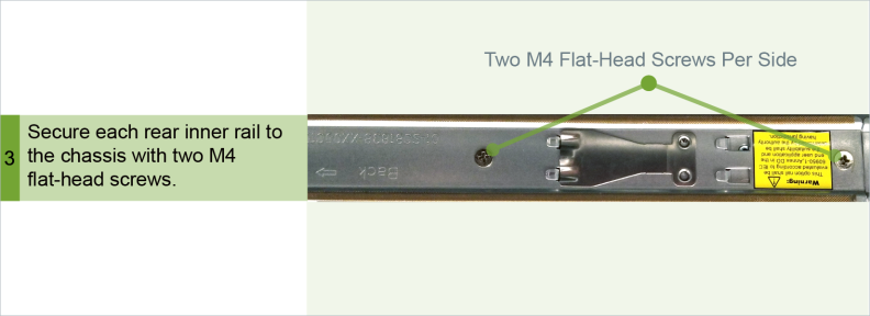
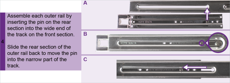
Install the rack rails using the instructions within the shipping rail contents.
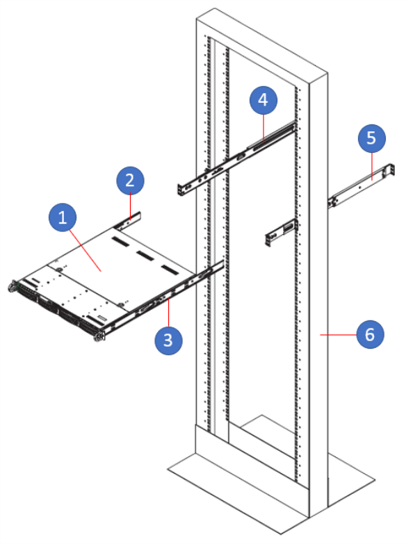
Item Description 1 VS2112-NVR 2 Left Chassis Rail 3 Right Chassis Rail 4 Left Rack Rail 5 Right Rack Rail 6 Rack - Install the NVR system rails using the instructions within the shipping rail contents.
-
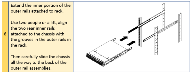
Line up the rear of the chassis rails with the front of the rack rails.
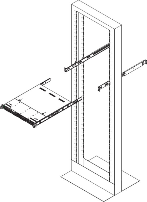
- Slide the chassis rails into the rack rails, keeping the pressure even on both sides (you may have to press the locking tabs when inserting).
- When the server has been pushed completely into the rack, you should hear the locking tabs "click".
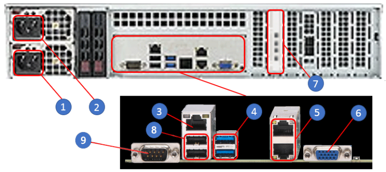
Connect the following cables to the system:
- Connect the power cords to PSU 0 and PSU 1 (items 1 and 2 below).
- Connect the IPMI LAN cable (item 3 below).
- Connect the LAN cables to the LAN ports (item 5 below).
- Connect the Keyboard and mouse each to a USB port (items 4 or 8 below).
- Connect the Monitor to one of the ports on the GPU card (item 7 below).
- Top: Port 10 (USB 3.0)
- Bottom: Port 9 (USB 3.0)
- Top: LAN2
- Bottom: LAN1
- Top: USB1 (USB 2.0)
- Bottom: USB0 (USB 2.0)
Connections:
| Item | Description |
|---|---|
| 1 | 800W Power Supply Receptacle (PSU 0) |
| 2 | 800W Power Supply Receptacle (PSU 1) |
| 3 | IPMI LAN Port (default IP: 192.168.17.21) |
| 4 | USB Ports: |
| 5 | LAN Ports: |
| 6 | VGA Port (not used) |
| 7 | Quad-port graphics processing unit (GPU) card with 4 x Mini-DisplayPort connections |
| 8 | USB Ports: |
| 9 | COM Port 1 |
Note: Before you power on the system, you need to connect a monitor, a keyboard, and a mouse to the system as shown in Step 3: Cable the System.
-
Press the power button on the system control panel to power on the VS2112-NVR.
Note: The system powers up in approximately three minutes.
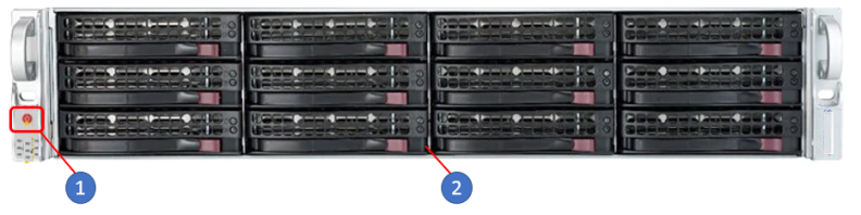
Item Description 1 Control Panel Power Button 2 VS2112-NVR -
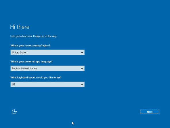
At the "Hi there" display, select your country/region, language, keyboard layout, and click Next.
-
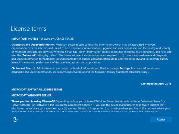
At the "License terms" display, read and click Accept.
-
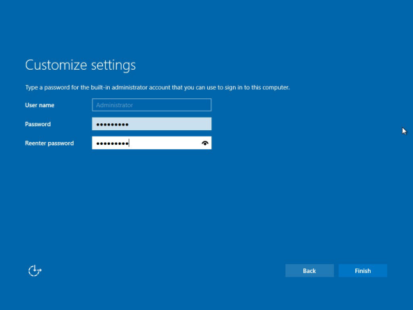
At the "Customize settings" display, create a password for the built-in administrator account, and click Finish.
-
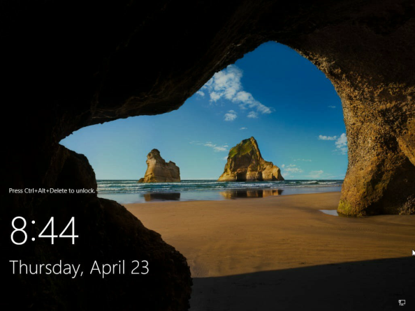
Verily that the Window OS display appears.
Note: The system is up and ready for configuring the network and remote access.
-
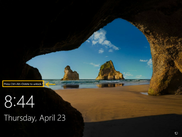
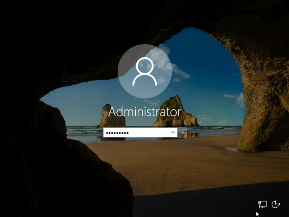
Press Ctrl+Alt+Delete to access the Administrator log in display.
Note: Quantum recommends that you select the "Domain join instead" option at the bottom left of the display rather than using another Microsoft user account.
-
Log on to Windows using the new "Administrator" user account credentials.
-
When Server Manager comes up, complete the following:
-
Select Local Server (on the left menu pane).
-
In the Network Connections window, select IPv4 address assigned by DHCP, IPv6 enabled.
Note: This interface is located on the back of the system and is the bottom port: LAN1 Port (management/cameras).
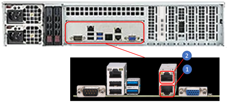
Item Description 1 LAN1 Port 2 LAN2 Port -
Select Properties.
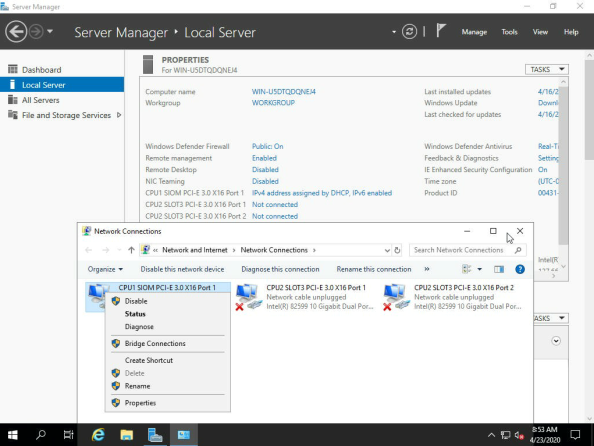
Note: Notice on the Network Connections display that the other interfaces have a red "X". This means that there are no cables connected.
-
-
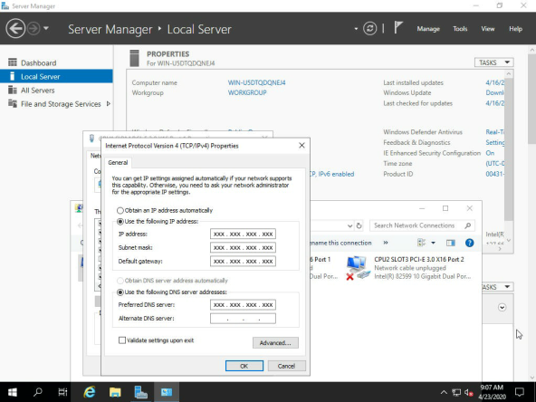
Add the static IP address information (IP address, Subnet Mask, and Default gateway at a minimum) and select OK.
Note: DNS is optional.
Note: Now the system can be reached remotely. You should enable remote access so that the server can be managed remotely using either the server’s IPMI, or Windows Remote Desktop.
-
Select Local Server
-
Select the applicable computer name (in this case: WIN-U5DTQDQNEJ4).
Note: A "System Properties" display appears.
-
Select Remote.
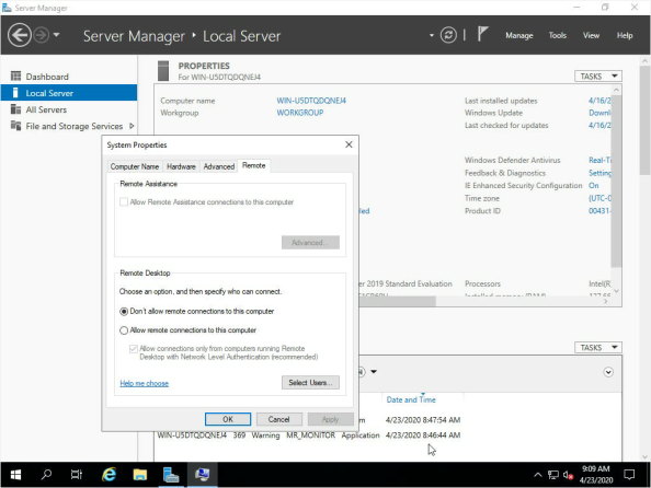
By default, the setting is Don’t allow remote connections to this computer.
-
Select Allow remote connections to this computer.
-
Verify that a "Remote Desktop Connection" display appears and select OK.
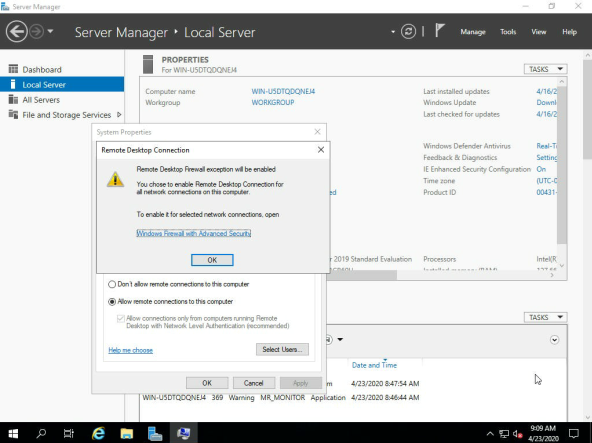
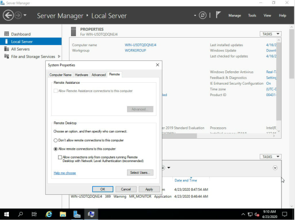
-
Uncheck the option for "Allow connections only from computers running Remote Desktop with Network Level Authentication (recommended)".
- Activate Microsoft Windows 10 using the Windows Product Key provided with the VS2112-NVR (location shown below). See Activate Windows 10 on the Microsoft web site.
-
Connect any additional LAN cables per customer's requirement.
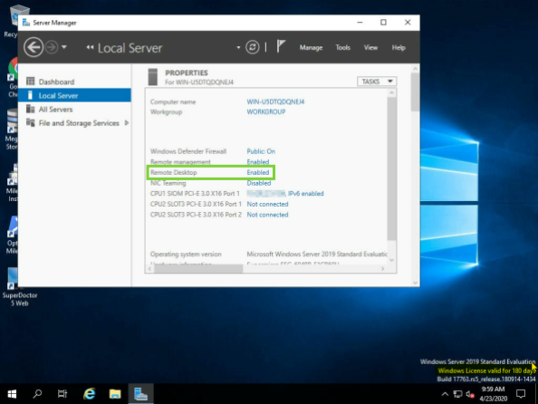
In the "Server Management" dialog, note the confirmation that "Remote Desktop" is now "Enabled".
Note: Quantum recommends you register Windows now, so there aren't problems registering the system later.
Note: That completes the Windows configuration for your NVR system.
Note: Quantum ships the NVR system with "Windows Defender" disabled.
- The camera count could be significantly impacted by 30% or more with Windows Defender enabled as compared to being disabled.
- Refer to Quantum VS-NVR Series specifications for additional information.
Once Windows is configured on the VS2112-NVR, configure your VMS:
- For the Milestone VMS, see the “Administrator manual” on the Milestone website for detailed installation and configuration instructions. Additional documentation is provided on that site for using the software after initial installation and configuration.
- For VMS other than Milestone, consult the manufacturer’s instructions for configuring the system.
-
If you have purchased a system with Milestone you will see the Milestone Installer icon on the desktop after the Windows configuration is complete.
To configure SuperDoctor 5, double-click the SuperDoctor 5 Web icon from the Windows desktop.
Additional Information about SuperDoctor 5:
- See the SuperDoctor 5 User's Guide for instructions on configuring the software.
- See the Alert Configuration section for information about configuring alerts.
- See the SuperDoctor 5 (SD5) web page for an overview of SuperDoctor 5..
Once configured, SuperDoctor 5 sends alerts for monitoring system health to appropriate personnel. See Monitor System Health.