minute read
H2000 Hardware Overview
Caution: Do not change any BIOS settings on your system.
The base system hardware specification (per RAID/controller node):
- 8-Core CPU
- 32 GB memory
- 256 GB boot drives (2x)
- Base system software:
- QBSP base system software and operating system (for 2.x systems ONLY)
- CentOS 7 running as a hypervisor (for 1.x systems ONLY)
- QCSP/ESOS VM (virtual machine; for 1.x systems ONLY):
- Network connection end-points are passed into the VM using PCI pass-through
- H-Series UI
RAID chassis specifications:
|
Specification |
Metric Unit |
Imperial Unit |
|---|---|---|
| Chassis height (2U) | 13.33cm (133.35mm) | 5.25 inches |
| Chassis depth | 66.04cm (660.4mm) | 26 inches |
| Chassis width (standard rack width) | 48.26cm (482.6mm) | 19 inches |
|
Chassis weight 12-drive chassis |
||
|
(fully-populated with hard drives) |
26.3 kg | 58 lbs. |
|
Chassis weight 24-drive chassis |
||
|
(fully-populated with hard drives) |
26.8 kg | 59 lbs. |
JBOD chassis specifications:
|
Specification |
Metric Unit |
Imperial Unit |
|---|---|---|
| Chassis height (2U) | 13.33cm (133.35mm) | 5.25 inches |
| Chassis depth | 52.07cm (520.7mm) | 20.5 inches |
| Chassis width (standard rack width) | 48.26cm (482.6mm) | 19 inches |
|
Chassis weight 12-drive chassis |
||
|
(fully-populated with hard drives) |
19.5 kg | 43 lbs. |
|
Chassis weight 24-drive chassis |
||
|
(fully-populated with hard drives) |
20.0 kg | 44 lbs. |
|
Item |
Component |
|---|---|
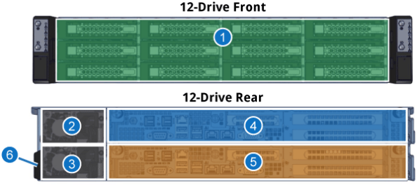
|
1 |
12 drive bays |
|
2 |
Power supply unit (PSU 2) |
|
3 |
Power supply unit (PSU 1) |
|
4 |
Controller B (top); redundant/failover operations supported with Controller A (bottom). |
| 5 | Controller A (bottom); redundant/failover operations supported with Controller B (top). |
| 6 | Serial Number/Asset Tag |
|
Item |
Component |
|---|---|
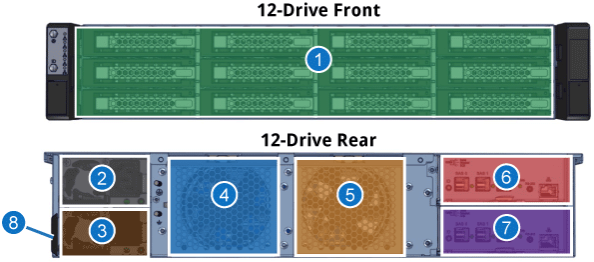
|
1 |
12 drive bays |
|
2 |
Power supply unit (PSU 2) |
|
3 |
Power supply unit (PSU 1) |
|
4 |
Left fan assembly; fan 1 is located in back; fan 3 is located in front |
| 5 | Right fan assembly; fan 2 is located in back; fan 4 is located in front |
|
6 |
Secondary JBOD I/O module (top); redundant/failover operations supported with the primary JBOD I/O module (bottom) |
| 7 |
Primary JBOD I/O module (bottom); redundant/failover operations supported with the secondary JBOD I/O module (top ) |
| 8 | Serial Number/Asset Tag |

|
Item |
Component |
|---|---|
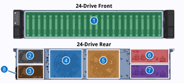
|
1 |
24 drive bays |
|
2 |
Power supply unit (PSU 2) |
|
3 |
Power supply unit (PSU 1) |
|
4 |
Controller B (top); redundant/failover operations supported with Controller A (bottom). |
| 5 | Controller A (bottom); redundant/failover operations supported with Controller B (top). |
| 6 | Serial Number/Asset Tag |
|
Item |
Component |
|---|---|
|
1 |
24 drive bays |
|
2 |
Power supply unit (PSU 2) |
|
3 |
Power supply unit (PSU 1) |
|
4 |
Left fan assembly; fan 1 is located in back; fan 3 is located in front |
| 5 | Right fan assembly; fan 2 is located in back; fan 4 is located in front |
|
6 |
Secondary JBOD I/O module (top); redundant/failover operations supported with the primary JBOD I/O module (bottom) |
| 7 |
Primary JBOD I/O module (bottom); redundant/failover operations supported with the secondary JBOD I/O module (top ) |
| 8 | Serial Number/Asset Tag |
The H2000 contains 3 drive types with different total system capacities and drive sizes for each type.
SSD capacity options
|
Drive Quantity |
Raw System Capacity |
Drive Size |
| 12 |
23 TB |
1.92 TB |
| 12 |
94 TB |
7.68 TB |
| 12 |
184 TB |
15.36 TB |
|
24 |
46 TB |
1.92 TB |
|
24 |
184 TB |
7.68 TB |
|
24 |
368 TB |
15.36 TB |
10K SAS capacity options
|
Drive Quantity |
Raw System Capacity |
Drive Size |
|
12 |
14 TB |
1.2 TB |
|
12 |
21 TB |
1.8 TB |
|
24 |
28 TB |
1.2 TB |
| 24 | 43 TB | 1.8 TB |
NL-SAS capacity options
|
Drive Quantity |
Raw System Capacity |
Drive Size |
| 12 |
48 TB |
4 TB |
| 12 |
96 TB |
8 TB |
| 12 |
192 TB |
16 TB |
|
24 |
96 TB |
4 TB |
|
24 |
192 TB |
8 TB |
|
24 |
384 TB |
16 TB |
The H2000 is designed for a StorNext shared storage environment.
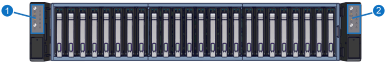
The front of the H2000 contains a drive bay that includes 12
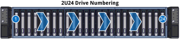
12-drive numbering
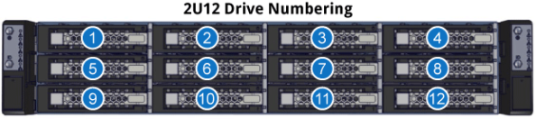
24-drive numbering
For 24 drive enclosures, drives are numbered from left to right and from 1 to 24 as shown below (a RAID enclosure is shown in this example, but the same numbering scheme applies to both RAID and JBOD enclosures):
Note: These apply to both controllers. (Single controller shown)
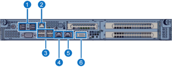
|
Item |
Component |
|
1 |
SAS expansion ports (for JBOD connections) |
|
2 |
IPMI/BMC 1 GbE (RJ-45) port |
| 3 | USB 3.1 Ports (qty. 4) |
| 4 | 10 GbE (RJ-45; Em1) – |
| 5 | 10 GbE (RJ-45 Em2) – used for initial system configuration; after configuration, this is for service use only |
| 6 | VGA Port (DB-15) |
Note: The H2000 is not available with a combination of both 32 Gb FC cards and 100 GbE cards installed in the same system.
H2000 Rear - PCIe Slot Locations
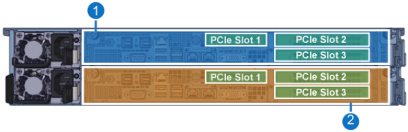
|
Item |
Description |
|
1 |
Controller B PCIe slot locations. |
|
2 |
Controller A PCIe slot locations. |
|
PCIe Slot |
Card Profile | Bracket Profile |
Cards Supported |
|---|---|---|---|
|
1 |
Low Profile | Low Profile |
Note: The Dell/Nvidia CONNECTX-6 DX 40/100 GbE NIC card requires QBSP 2.2 or later software) |
|
2 |
Low or Full Height | Full Height | |
|
3 |
Low Profile | Full Height |
Ethernet port listed in this table has a physical location on the supported PCIe Ethernet cards, and corresponds to a logical port address (which is used when configuring the port, or when trying to identify the port on various displays in the H-Series UI (see Configuration > Storage Interfaces).
Note: For iSCSI configuration, ports use "s" rather than "p" for the slot number. For example, for a Quad-port Eth card in slot 1, port 1 would look like "s513p1", rather than "p513p1", as shown in the "iSCSI Port Address" in the table.
|
Physical Port Location |
Logical Port Address |
iSCSI Port Address
|
|---|---|---|
|
Rear System Eth Port 1 |
em1 | n/a |
|
Rear System Eth Port 2 |
em2 | n/a |
| For Quad-Port Eth Cards in PCIe Slot 1: | ||
|
Slot 1 Port 1 |
p513p1 | s1p1 |
| Slot 1 Port 2 | p513p2 | s1p2 |
| Slot 1 Port 3 | p513p3 | s1p3 |
| Slot 1 Port 4 | p513p4 | s1p4 |
| For Dual-Port Eth Cards in PCIe Slot 1: | ||
|
Slot 1 Port 1 |
p513p1 | s1p1 |
| Slot 1 Port 2 | p513p2 | s1p2 |
| For Quad-Port Eth Cards in PCIe Slot 2: | ||
| Slot 2 Port 1 | p257p1 | s2p1 |
| Slot 2 Port 2 | p257p2 | s2p2 |
| Slot 2 Port 3 | p257p3 | s2p3 |
| Slot 2 Port 4 | p257p3 | s2p4 |
| For Dual-Port Eth Cards in PCIe Slot 2: | ||
| Slot 2 Port 1 | p257p1 | s2p1 |
| Slot 2 Port 2 | p257p2 | s2p2 |
| For Quad-Port Eth Cards in PCIe Slot 3: | ||
| Slot 3 Port 1 | p258p1 | s3p1 |
| Slot 3 Port 2 | p258p2 | s3p2 |
| Slot 3 Port 3 | p258p3 | s3p3 |
| Slot 3 Port 4 | p258p4 | s3p4 |
| For Dual-Port Eth Cards in PCIe Slot 3: | ||
| Slot 3 Port 1 | p258p1 | s3p1 |
| Slot 3 Port 2 | p258p2 | s3p2 |
The cards listed in this table have specific ports when looked at from the rear of the chassis, from left to right. The ports used are included below, in the order found on the system for each.
|
Card |
Slot Location |
Port and Port Order |
Host Port Names |
|---|---|---|---|
|
Quad Port Eth Cards |
Slot 1 |
1-2-3-4 |
s1p1, s1p2, s1p3, s1p4 |
|
Slot 2 |
4-3-2-1 |
s2p4, s2p3, s2p2, s2p1 |
|
|
Slot 3 |
4-3-2-1 |
s3p4, s3p3, s3p2, s3p1 |
|
|
Dual Port Eth Cards |
Slot 1 |
1-2 |
s1p1, s1p2 |
|
Slot 2 |
2-1 |
s2p2, s2p1 |
|
|
Quad Port FC Cards |
Slot 1 |
0-1-2-3 |
|
|
Slot 2 |
3-2-1-0 |
|
|
|
Slot 3 |
3-2-1-0 |
|
|
|
Dual Port FC Cards |
Slot 1 |
0-1 |
|
|
Slot 2 |
1-0 |
|
|
|
Slot 3 |
1-0 |
|
See Interface Card/Switch Compatibility in the Planning section of this doc center.
Note: These apply to both I/O Modules.
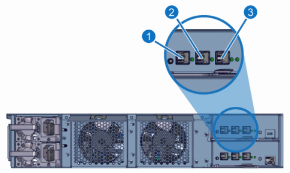
|
Item |
Component |
|
1 |
SAS 0 Port |
|
2 |
SAS 1 Port |
| 3 | SAS Expansion Port |
|
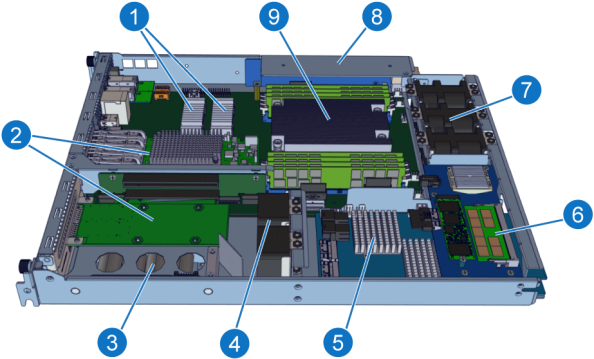
Item |
Component |
|
1 |
Host Operating System/Boot Drive SSDs |
|
2 |
I/O Expansion Cards (3 slots total) |
|
3 |
SuperCap/Battery Backup Unit (BBU) |
|
4 |
I/O Expansion Card Fans (2x) |
|
5 |
3-in-1 Card |
|
6 |
NVD (Non-Volatile DRAM) Card |
|
7 |
System Fans (3x) |
|
8 |
RAID Power Supply Unit (PSU) |
|
9 |
Motherboard; includes:
For additional RAID port information, see Controller Port Connections. |
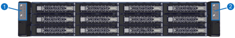
|
Item |
LED/Button |
|
1 |
Left Front Control Panel (Controller A) |
|
2 |
Right Front Control Panel (Controller B) |
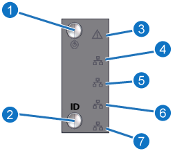
RAID Control Panel LEDs and Buttons (both control panels)
|
Item |
LED/Button* |
Indication/Function |
|
1 |
Controller Power Status |
Blue: Power on Off: Power off |
|
2 |
Controller ID (LED/button) |
Blue: Controller ID enabled Off: ID not lit |
| 3 | Controller Status (LED) |
Red: Controller degraded Off: Controller healthy |
|
4 |
LAN Port 1 activity |
Yellow: LAN1 (10 GbE) network activity Off: LAN1 link is down |
| 5 | LAN Port 2 activity |
Yellow: LAN2 (10 GbE) network activity Off: LAN2 link is down |
| 6 | NVD Save/Restore Activity |
Blinking: NVD is saving or restoring data |
| 7 | NVD PCIe Up/Ready |
On: NVD is healthy and connected to the PCIe interfaces |
| * LED/button displayed is specific to each controller's panel: Controller A - left control panel; Controller B - right control panel | ||
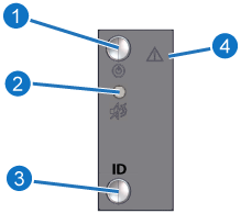
JBOD Control Panel LEDs and Buttons (control panel on left ear only)
|
Item |
LED/Button* |
Indication/Function |
|
1 |
JBOD Power Status |
Blue: Power on Off: Power off |
|
2 |
JBOD Alarm Mute (button) |
Mute audible system alarms |
| 3 | JBOD ID (LED) |
Blue: JBOD ID enabled Off: ID not lit |
|
4 |
System Status LED |
Off: System Healthy Red: System degraded |
|
Item |
LED Location |
LED State |
|---|---|---|
|
1 |
Top Drive LED |
Off: System off or drive not fully-seated Solid Blue: Online/Healthy status Blinking Blue: Drive access detected |
|
2 |
Bottom Drive LED |
Off: Healthy; no drive failure detected Solid Red: Drive error |
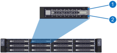
24 Control Panels
|
Item |
LED/Button |
|
1 |
Left Front Control Panel (Controller A) |
|
2 |
Right Front Control Panel (Controller B) |
RAID Control Panel LEDs and Buttons (both control panels)
|
Item |
LED/Button* |
Indication/Function |
|
1 |
Controller Power Status |
Blue: Power on Off: Power off |
|
2 |
Controller ID (LED/button) |
Blue: Controller ID enabled Off: ID not lit |
| 3 | Controller Status (LED) |
Red: Controller degraded Off: Controller healthy |
|
4 |
LAN Port 1 activity |
Yellow: LAN1 (10 GbE) network activity Off: LAN1 link is down |
| 5 | LAN Port 2 activity |
Yellow: LAN2 (10 GbE) network activity Off: LAN2 link is down |
| 6 | NVD Save/Restore Activity |
Blinking: NVD is saving or restoring data |
| 7 | NVD PCIe Up/Ready |
On: NVD is healthy and connected to the PCIe interfaces |
| * LED/button displayed is specific to each controller's panel: Controller A - left control panel; Controller B - right control panel | ||
JBOD Control Panel LEDs and Buttons (control panel on left ear only)
|
Item |
LED/Button* |
Indication/Function |
|
1 |
JBOD Power Status |
Blue: Power on Off: Power off |
|
2 |
JBOD Alarm Mute (button) |
Mute audible system alarms |
| 3 | JBOD ID (LED) |
Blue: JBOD ID enabled Off: ID not lit |
|
4 |
System Status LED |
Off: System Healthy Red: System degraded |
24 Drive LEDs
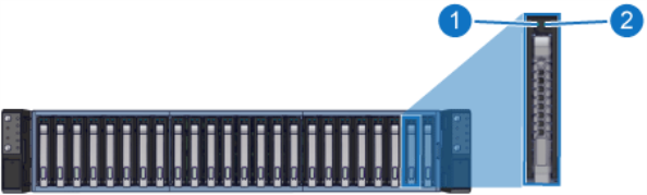
|
Item |
LED Location |
LED State |
|---|---|---|
|
1 |
Left Drive LED |
Off: System off or drive not fully-seated Solid Blue: Online/Healthy status Blinking Blue: Drive access detected |
|
2 |
Right Drive LED |
Off: Healthy; no drive failure detected Solid Red: Drive error |
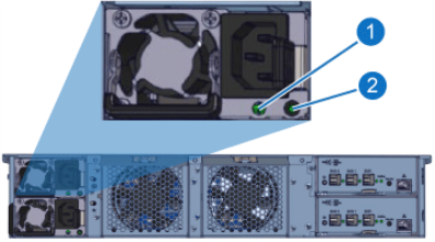
The PSU LEDs are located in the same position on PSU 1 and PSU 2. Location and description of the LEDs:
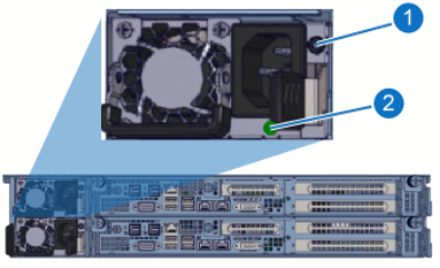
|
Item |
LED/Button |
Action |
|
1 |
PSU Alarm Silence Button |
Push to silence when alarm is sounding |
| 2 | PSU Status |
|
The PSU LEDs are located in the same position on PSU 1 and PSU 2. Location and description of the LEDs:
|
Item |
LED |
Action |
|
1 |
PSU power |
|
| 2 | PSU Status |
|
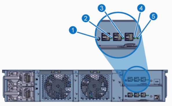
|
Item |
LED |
Action |
|
1 |
ID LED/Button |
|
|
2 |
SAS 0 |
|
|
3 |
SAS 1 |
|
|
4 |
SAS Connection |
|
|
5 |
I/O Module |
|