Site Planning
The system shipment includes a minimum of one 1U12 base system node, or two 1U12 base system nodes and RAID/JBOD expansion systems shipped on a pallet.
| Base System Node | |
|---|---|
| Box Dimensions |
45.75 x 21.75 x 7.75 (inches) 116.2 x 55.2 x 19.7 (cm) |
| Box Weight |
76 lbs 34 kg |
Each base system node carton contains the following:
-
1U12 Server Chassis (drives installed)
-
C13/14 13A/250V Power Cables (5 ft.)
-
Base System Kit (includes Getting Started Card and anti-static wrist strap)
-
Rail Mounting Kit
-
CAT 6A, RJ45 Cables (6 ft.)
-
10/25 GBe SFP28 Direct Attach Cables (3 meters)
The system is delivered on one or more pallets and is installed on-site. This section describes the space required for unpacking and installation.
Use the following guidelines regarding build space during installation:
-
Plan an unpacking and installation sequence if there is not enough space to unpack and store all of the components at once.
-
While installing system components, a minimum of 48 in (1220 mm) of space is required at the front of the rack. This allows for the largest system component to be installed by two people. If space is not available in the location where the system will operate, consider building the system outside the operational location and moving it into location when finished.
-
If the system will be moved after being built, measure the size of the rack and check the walking path to ensure that the rack will fit as it moves through the deployment site.
Note: Before moving the system, verify that the rack can support the dynamic load of the system weight during movement.
During the receiving process, the system will need to be moved through the facility until it reaches the data center or computer room where it will be installed. This section describes the considerations that the installation team should make before receiving the system and moving it through the facility.
Walking paths must be clear of obstructions and wide enough to allow passage of the packaged system to the location where it will be unpacked. The following is a list of obstructions to consider when conducting a walking path inspection:
| Cables | Consider removing cables, including ramped cable covers, from the walking path before moving the pallet. Leaving the cables in place creates a safety hazard for the installation team and can damage the cables. |
| Lift Locations | There may be locations along the walking path where the system must be lifted in order to proceed. Make sure that lift equipment is available at this location on the day of the delivery. |
| Elevators | Ensure that any elevators that will be required to lift the equipment to the data center/computer room are rated to carry the full load of the system plus passengers. |
| Security | Make sure that all site security requirements adhered to and that all personnel are made aware of the parameters under which they must work. |
|
Characteristic |
Specification |
|---|---|
|
Server Width (side to side) |
17.2 in. (43.7 cm) |
| Server Depth (front) | 23.5 in. (59.7 cm) |
| Server Height | 1.7 in. (4.3 cm) |
| Rack Space Requirements - Servers |
|
|
Mount Hardware/ |
Specification |
|---|---|
|
Mounting Hardware |
|
| Rack Hole Types |
|
| Rack Width | 19 in (48.3 cm) |
| Rack Depth | 28.4 in (72.06 cm) |
The system is installed into a customer-supplied rack. Use the guidelines in this section to choose an appropriate rack mounting solution.
Note: The absolute minimum depth requirement for the system is 42.12 in (1070 mm). However, Quantum recommends selecting a rack with a minimum depth of 48 in (1200 mm) to allow for proper PDU installation and cable routing.
Depending on the specific optional components and configuration options, use the following additional guidelines when choosing a rack mounting solution.
| System Dimensions |
Select a rack mounting solution that has the appropriate depth to accommodate the following:
|
| Rail Kits |
|
| System Weight |
Select a rack mounting solution that can withstand the following:
|
| Cable Management | The system is designed so the cables are wired at the back of the system. Ensure that the system cabling can be routed safely and efficiently through the selected route. |
| Grounding | Ensure that both the electrical components used to power the system and the rack itself can be grounded safely. |
The front and rear of the system must be clear of any materials that could block or disrupt system airflow. Disruption of airflow can cause performance issues or system damage due to overheating.
Use the following guidelines to ensure proper system airflow:
-
The airflow in and out of the equipment must not be restricted.
-
Controlled air conditioners that are functional and can sufficiently maintain specified system operating temperatures should be located in the facility where the system will be installed.
-
If rack doors will be used, ensure that the solution used with the system does not prevent airflow from the cold aisle from entering the system freely.
|
Airflow Requirement |
Specification |
|---|---|
|
Racks Without Doors |
6.5 in. (16.5cm) |
| Racks With Doors (front/back) | 23 in. (58.4cm) |
Each server chassis contains two 750 watt power supply units (PSU) for redundancy.
The system does not come with its own power distribution unit (PDU). To prevent the potentially negative effects of excessive inrush current on the system, Quantum recommends selecting a PDU that can stagger the start-up sequence of the system components. If a PDU that cannot stagger the start-up sequence is used, ensure that the PDU is rated to support the inrush current caused by a simultaneous start-up.
|
Characteristic |
Specification |
|---|---|
| AC Input Voltages | 100-240 VAC |
| Rated Input Current | 8.5 A to 6 A |
| Rated Input Frequency | 50-60 Hz |
| Rated Output Power | 750 Watts |
| Rated Output Voltages | +3.3 V (25 A), +5 V (25 A), +12 V (700 W: 58 A at 100 V-140 V, 750 W: 62 A at 180 V-240 V), -12 V (0.6 A), +5 Vsb (3 A) |
| Power Consumption |
|
Quantum recommends you acclimate the server node to ambient temperature prior to power up to avoid condensation or other effects of temperature change.
|
Characteristic |
Specification |
|---|---|
| Operating Temperature | 10º to 35º C (50º to 95º F) |
| Non-operating Temperature | -40º to 60º C (-40º to 140º F) |
| Operating Relative Humidity | 8% to 90% (non-condensing) |
| Non-operating Relative Humidity | 5% to 95% (non-condensing) |
In order for StorNext, StorNext Connect, the StorNext Unified UI, license reporting, software updates, and CBA to fully function, the following host names should be added to the firewall rules for your network for https port 443:
-
stornextconnect.quantum.com
-
api-stornextconnect.quantum.com
-
mystornext.quantum.com
-
api-mystornext.quantum.com
-
insight.quantum.com
-
api-as.quantum.com
See Port Configuration for information about the ports used by StorNext software.
- A Storage Area Network (SAN) compatible with the Fibre Channel (FC) network speed supported by the FC HBA cards, depending on the option(s) chosen for the system.
- An FC( Fibre Channel) switch supporting the network speed needed by the FC HBA card(s) chosen for the system.
- A Local Area Network (LAN) compatible with the on-board 1 GbE NIC ports for the metadata and management networks, and the network speeds supported by the NIC HBAs/HCAs cards chosen for the system.
- A Local Area Network (LAN) compatible with the network speeds and protocols required for the NIC HBA/HCA cards installed in the system.
- Network switch(es) compatible with the network speeds and protocols required for the NIC HBA/HCA cards installed in the system.
Note: Mounting a PDU or other equipment vertically in the rack can hinder the ability to service components.
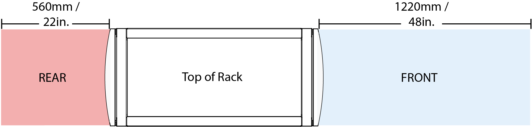
To properly install and service system components, Quantum recommends the following space at the front and rear of the system.
|
Specification |
Value |
|
Minimum front of rack space |
48 in (1220 mm) |
|
Minimum rear of rack space |
22 in (560 mm) |
| Electromagnetic Emissions | FCC Class A, EN 55032 Class A, EN 61000-3-2/3-3, CISPR 32 Class A |
| Electromagnetic Immunity | EN 55024/CISPR 24, (EN 61000-4-2, EN 61000-4-3, EN 61000-4-4, EN 61000-4-5, EN 61000-4-6, EN 61000-4-8, EN 61000-4-11), CNS14336-1, CNS13438, GB4943.1-2011, GB9254-2008(Class A) and GB17625.1-2012 |
| Safety | CSA/EN/IEC/UL 60950-1 Compliant, UL or CSA Listed (USA and Canada), CE Marking (Europe) |
| Other | VCCI-CISPR 32 and AS/NZS CISPR 32 |
|
Environmental |
Directive 2011/65/EU and Delegated Directive (EU) 2015/863 and Directive 2012/19/EU |
See the Hardware Overview to view images of the server node and its hardware specifications.