minute read
Hardware Overview
The Quantum Xcellis Workflow Director Gen 3 system is a work-flow storage system with various configurations and options to meet your evolving storage performance and capacity needs. The StorNext Unified User Interface and the StorNext UI provide ongoing holistic monitoring of your entire StorNext environment after initial configuration.
System components include:
- One or two server nodes
- One RAID Chassis
- JBOD/Expansion Chassis (optional)
- Additional RAID Chassis (optional)
- Additional JBOD/Expansion Chassis connected to the additional RAID chassis (optional)
Figure 1: Minimum Xcellis Workflow Director Gen 3/H-Series/F-Series configuration: an Xcellis Workflow Director system configured with a single server node, and a single 2U H-Series RAID or F-Series, and no JBODs
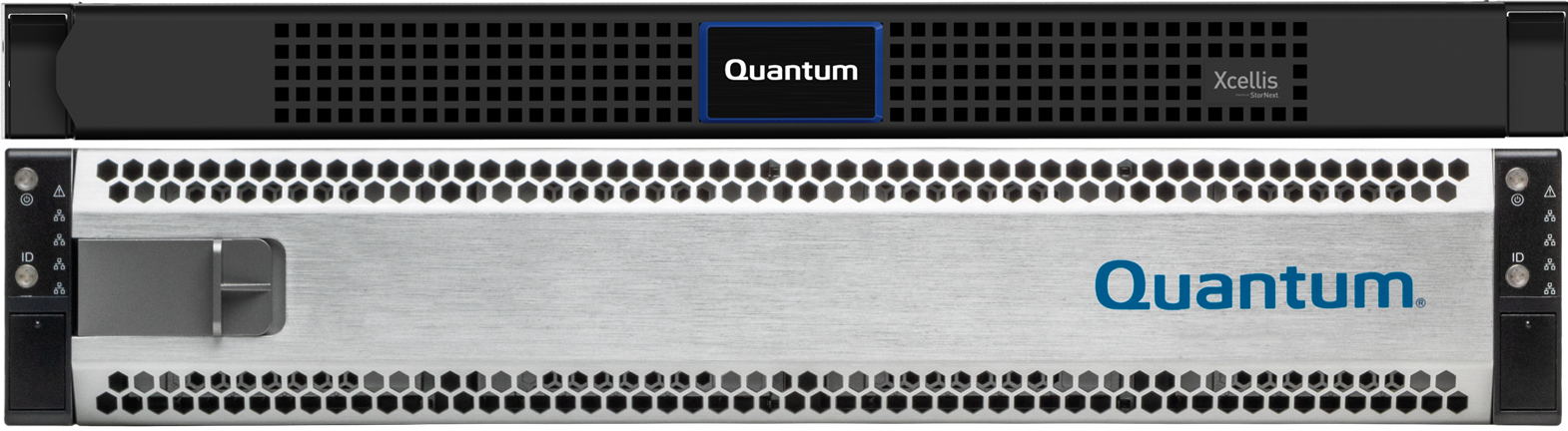
Figure 2: Minimum Xcellis Workflow Director Gen 3/QXS configuration: Xcellis Workflow Director system configured with a single server node, and a single 2U QXS RAID, and no JBODs
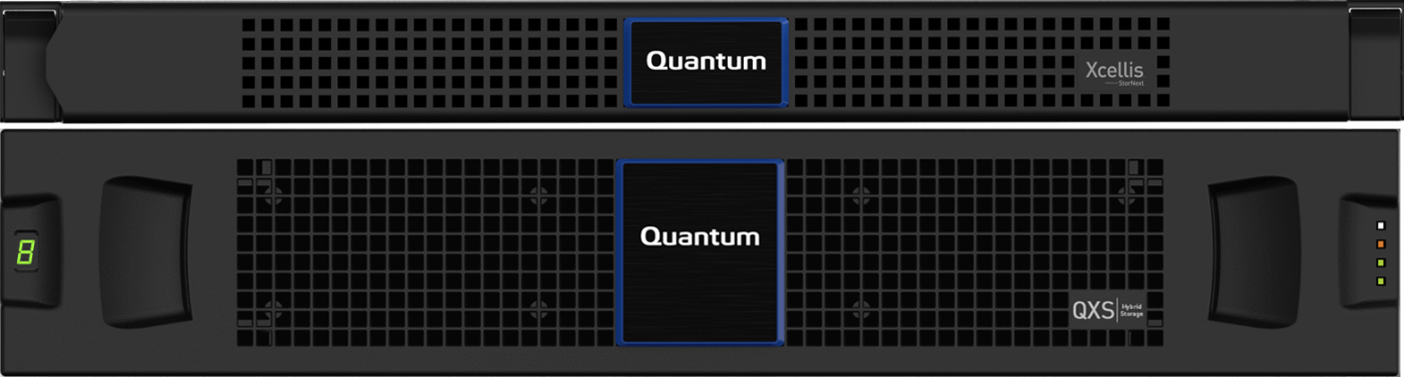
Figure 3: Typical Xcellis Workflow Director Gen 3/H-Series/F-Series configuration: Xcellis Workflow Director system configured with a single server node, and a single 2U H-Series RAID or F-Series, and no JBODs
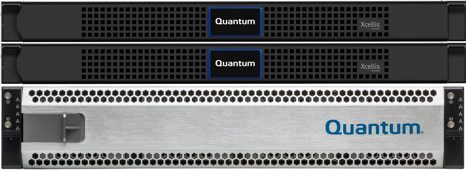
Figure 4: An Xcellis Workflow Director System Configured with Two Workflow Director Nodes, and a QXS 2U RAID Chassis

Figure 5: Maximum Xcellis Workflow Director Gen 3/H-Series configuration: H-Series configuration: an Xcellis Workflow Director system configured with a single server node, a single 2U H-Series RAID, and three 2U H-Series JBODs
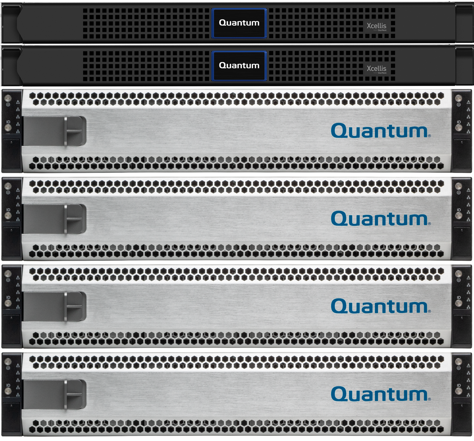
Figure 6: An Xcellis Workflow Director Gen 3 System Configured with Two Workflow Director Nodes, a QXS 2U RAID Chassis, and a QXS-456 Expansion Chassis
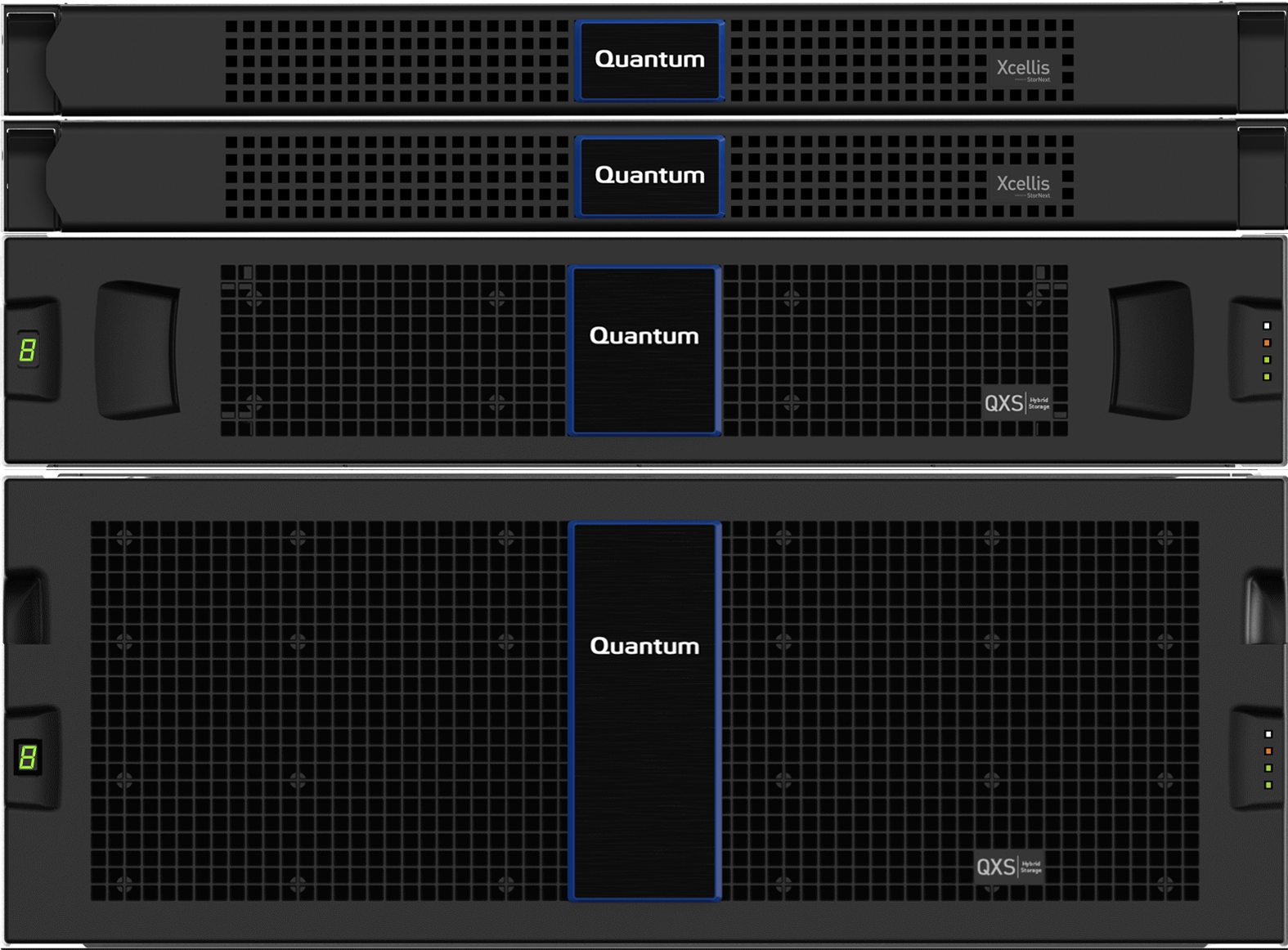
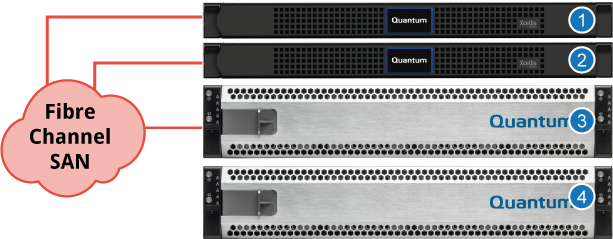
The system is offered with converged metadata and user data storage or with dedicated metadata storage in different configuration options. The following figures illustrate the supported configurations. Your storage configuration may be different than those shown here.
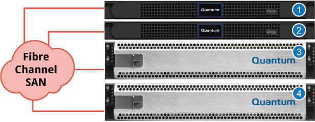
Figure 7: Two Server Nodes With Converged Metadata/User Data on H-Series Storage
|
|
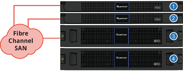
Figure 8: Two Server Nodes With Converged Metadata/User Data on QXS Storage
|
|
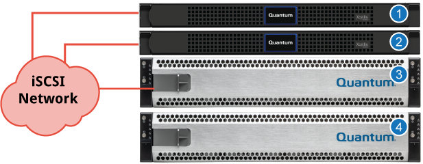
The system is offered with converged metadata and user data storage or with dedicated metadata storage in different configuration options. The following figures illustrate the supported configurations. Your storage configuration may be different than those shown here.
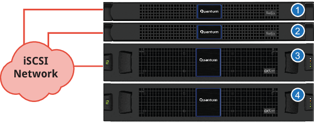
Figure 9: Two Server Nodes with Converged Metadata/User Data Storage and iSCSI Connections
|
|
Figure 10: Two Server Nodes with Converged Metadata/User Data Storage and iSCSI Connections
|
|
The system is offered with converged metadata and user data storage or with dedicated metadata storage in different configuration options. The following figures illustrate the supported configurations. In the QXS example, a 56-Drive Chassis is used for user data. Your storage configuration may be different than those shown here.
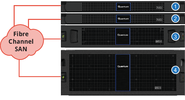
Figure 11: Two Server Nodes With Separate Dedicated Metadata and User Data Storage
|
|
Figure 12: Two Server Nodes With Separate Dedicated Metadata Storage and User Data on 56-Drive Storage
|
|
The system is offered with converged metadata and user data storage or with dedicated metadata storage in different configuration options. The following figures illustrate the supported configurations. Your storage configuration may be different than those shown here.
Figure 13: Two Server Nodes With Separate Dedicated Metadata and User Data Storage

Figure 14: Two Server Nodes With Separate Dedicated Metadata and User Data Storage
Hardware
-
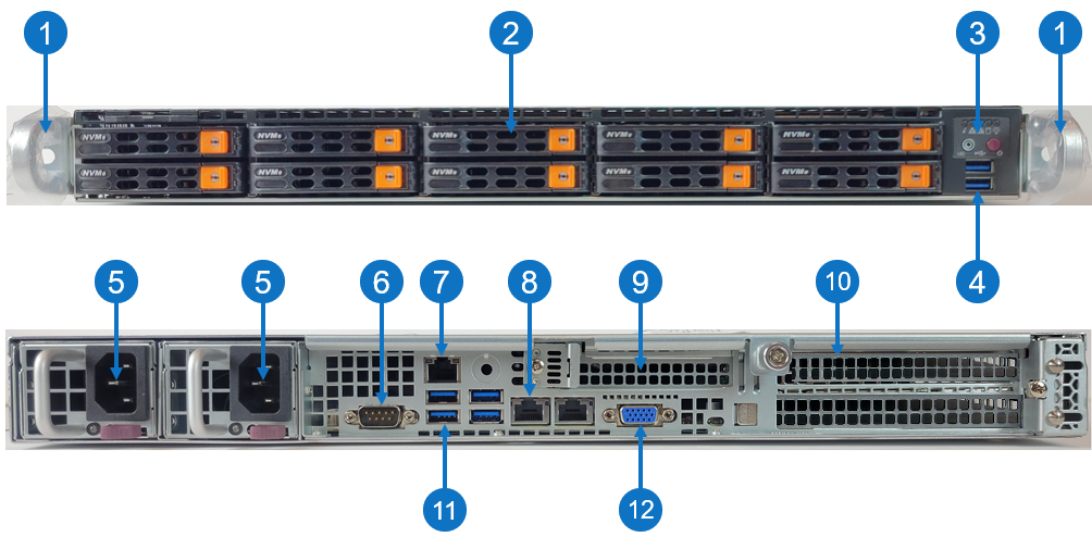
1U Server running Rocky 8 Linux, 256 GB RAM (standard) to 512 GB RAM (maximum), 32-Core CPU, PCIe4
-
1 x slot for low-profile, half length (LPHL) expansion (add-on) card
-
2 x slots for full height, half length (FHHL) expansion cards
-
2 x 960 GB M.2 NVMe (boot) drives
-
2 x 960 GB 2.5" NVMe flash (data) drives
-
2 x dual power, redundant fans
Features
| Item | Description |
|---|---|
| 1 |
Front handles WARNING: Do not pick up the node with the front handles. They are designed to pull the system from a rack only. |
| 2 |
(10) Drives bays for 2.5" hot-swap drive carrier Note: Only two NVMe flash drives are used in slot 1 and slot 2. |
| 3 | Control panel |
| 4 | (2) USB storage port |
| 5 |
(2) Hot-swappable redundant, load-sharing AC power supply unit (PSU)
|
| 6 | COM port |
| 7 | RJ-45 100/1,000 BASE-T IPMI port |
| 8 |
(2) RJ-45 1,000/10,000 BASE-T management port (left port # 1 and right port # 2) Note: Each server node contains an integrated Ethernet port (known as the Service Port) that is used for initial system installations. If you desire to directly connect to the system, connect an Ethernet cable from the Ethernet port of a service laptop to the Service Port (the left port # 1) on the rear of the server node you wish to access. |
| 9 |
Expansion card slot (slot 1) for low-profile, half length (LPHL) expansion (add-on) card The server has different network and Fibre Channel connection options depending on the expansion cards purchased. This card slot only runs at the PCIe Gen 3 speeds (maximum speed is approximately 15.76 GB/s) and supports the following expansion cards:
|
| 10 |
(2) Expansion card slot (top slot is slot 2 and bottom slot is slot 3) for full height, half length (FHHL) expansion card The server has different network and Fibre Channel connection options depending on the expansion cards purchased. This card slot supports the following expansion cards:
|
| 11 | (4) USB storage port |
| 12 | VGA port |
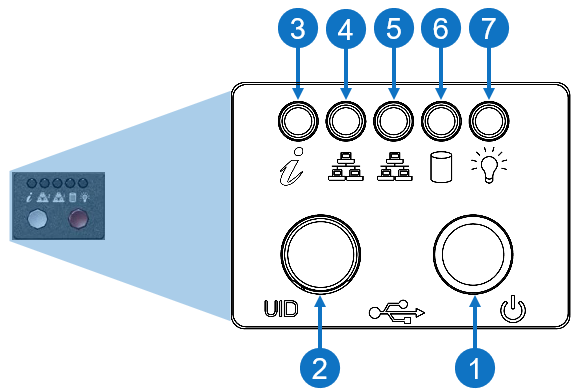
Control Panel LEDs
|
Item |
LED/Button |
Indication/Function |
|
1 |
Power button |
Use the main power switch to apply or remove power to the node. If you turn off the system power with this button, then the process removes the main power but keeps standby power supplied to the node. Caution: You must unplug the AC power cord before you service the node. |
| 2 | Unit identifier (UID) button |
Press the button to illuminate an LED on both the front and rear of the node for easy system location in a rack configuration. The LED remains on until the button is pushed a second time.
|
| 3 | Universal information |
|
|
4 |
10/100/1000BASE-T RJ-45 port |
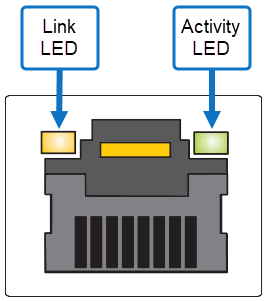
Indicates network activity on the management port # 1. The physical port LEDs represent the following:
Link LED
Activity LED
|
|
5 |
10/100/1000BASE-T RJ-45 port |
Indicates network activity on the management port # 2. The physical port LEDs represent the following:
Link LED
Activity LED
|
| 6 | SSD | When flashing, indicates drive activity. |
| 7 | Power | Indicates power is supplied to the system's power supply units; this LED illuminates when the system is operating normally. |
Review the hardware overview section for your H-Series product on the Quantum Documentation Portal.
Review the hardware overview section for your F-Series product on the Quantum Documentation Portal.
Review the hardware overview section for your QXS storage product on the Quantum Documentation Portal.