minute read
Common Operations
This section describes how to perform common operations on the F1000, including changing configuration settings using the F-Series UI, the BMC Web User Interface, or the QCSP/TUI.
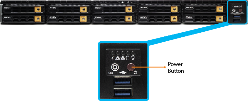
Press and release the Power button on the front of the F1000.
Note: Wait for the system to boot before logging on. This can take several minutes.
Caution: Before powering off the F1000, be sure to stop client I/O.
Press and release the Power button on the front of the F1000:
When you power off the F1000, the system shuts down the Host OS, and powers off the server.
Use the UI to update F1000 1.x platform software to QBSP 2.2
Prerequisites
Your system must be running QBSP 2.1.
Note: The update to QBSP 2.1 is a manual process. Contact your Quantum support or your Quantum Service Provider to schedule your update. For Quantum support and Quantum Service Providers, see Update software to QBSP 2.0.2 or 2.1 (CSWeb log in is required).
Do the following to update your software to QBSP 2.2.
Note: The QBSP upgrade process results in multiple reboots of the controller if your system BIOS, network, or FC card firmware require an update.
-
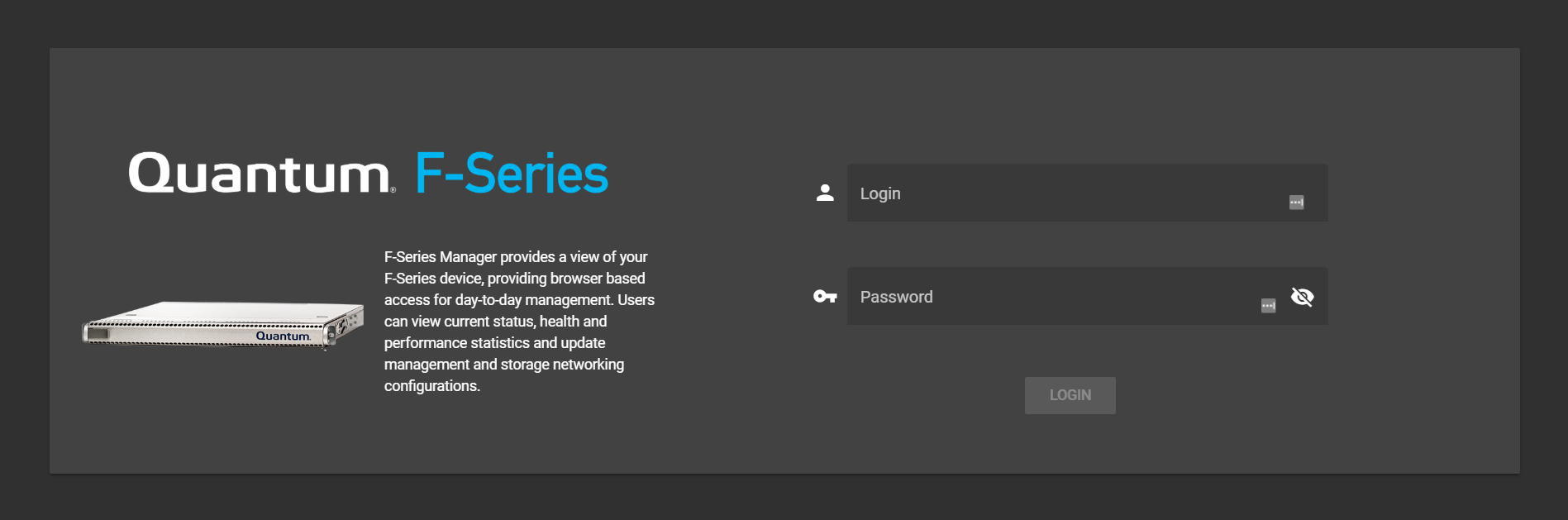
Log In to the F-Series UI.
- Access the log in page using the management IP address.
- Enter your credentials, and then click Login.
- On the top navigation, click Configuration.
- On the left navigation, click Update Platform Software.
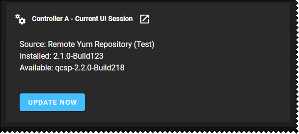
- On the Update Platform Software page, select the Source and then click Check for Update.
- Quantum Remote Repository: Select this option if your system is connected to the internet and want to perform an online update.
- Local Platform Update: Select this option, if your system is not connected to the internet and you want to update the software locally (offline).
- If a software update is available, click Update Now.
- On the confirmation dialog, click Update to begin the update process, or click Cancel to abort the operation and return to the previous page.


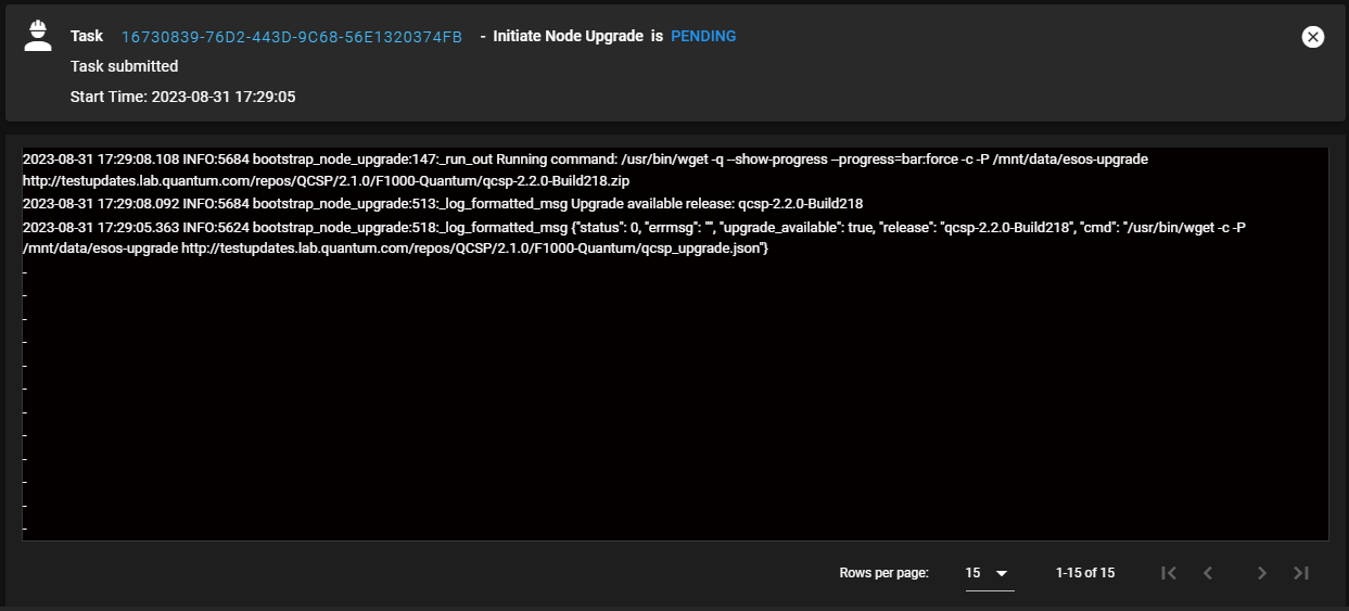
Note: Allow 10-15 minutes to download the software and prepare for your upgrade. The upgrade process remains in a pending state until the upgrade is complete and the reboot is initiated. Status updates for the upgrade appear with the most recent updates at the top of the Task Monitor Log. After the upgrade completes and the reboot is initiated, the UI session is disconnected. Allow up to five minutes for your system to regain UI access.
Example of the Task Monitor Log
To monitor, or stop monitoring the F1000 using SNMP (Simple Network Management Protocol):
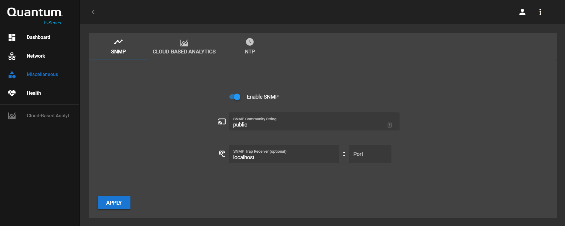
- In the F-Series UI, select Miscellaneous in the left navigation menu.
-
Click the SNMP tab.
- Click the Enable SNMP toggle. It turns blue, indicating it is enabled.
-
Enter the SNMP Community String. The default is
public.Note: To avoid security issues, change this value.
- Enter the SNMP Trap Receiver, if needed. The default is
localhost. - Enter the Port for the SNMP trap receiver. There is no default port value.
- Click Apply to confirm the change.
Note: The SNMP Trap Reciever is the hostname of the system that collects SNMP traps. If set to "localhost", SNMP data won't go anywhere. When enabling SNMP, change this to the hostname of the trap receiver used for SNMP. If this is left as "localhost", SNMP data will not be collected.
- In the F-Series UI, select Miscellaneous in the left navigation menu.
- Select the SNMP tab.
- Click the SNMP toggle. It turns gray, indicating it is disabled.
- Click Apply to confirm the change.
About CBA for the F1000
The benefits of enabling CBA on the F1000 include:
- The ability to monitor F1000 system health at-a-glance anytime, anywhere
- Allows you to quickly isolate issues in complex, multi-product environments and fix them, for reduced system downtime
- Provides for the best support experience
You must have an account to enable Cloud-Based Analytics (CBA). To request a CBA account, click the Request an account link in the Cloud-Based Analytics site at insight.quantum.com.
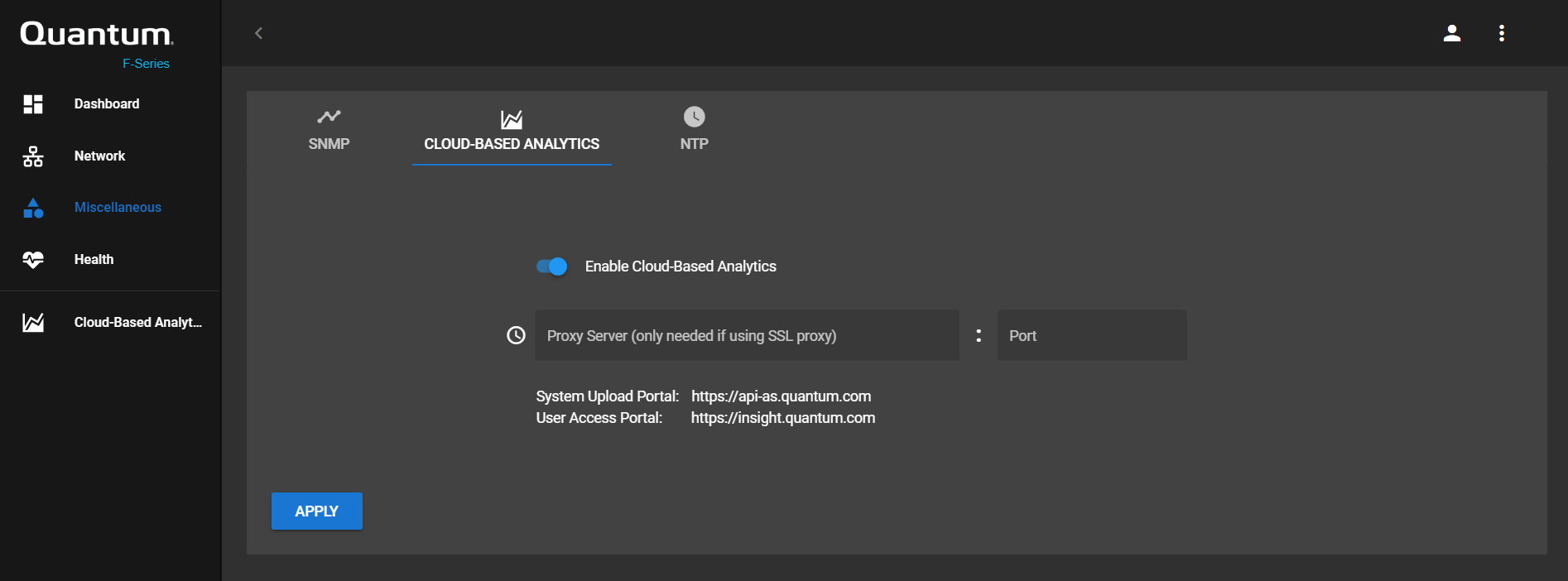
- In the F-Series UI, select Miscellaneous in the left navigation menu.
- Click the CLOUD-BASED ANALYTICS tab.
- Click the Enable Cloud-Based Analytics toggle. It turns blue, indicating it is enabled.
- Enter the Proxy Server name, if you are using an SSL proxy.
- Enter the Port number for that proxy server, if you are using an SSL proxy.
- For now, leave the Device Registration ID blank. You must have an account before you populate this ID. To request a CBA account, click the Request an account link in the Cloud-Based Analytics site at insight.quantum.com. The system can be found on the CBA portal for your particular Solution.
- Click Apply to confirm the change.
You can request an account and verify your F1000 is listed in the CBA portal using the steps below.
Note: If your solution includes more than one device (such as additional F1000s or Xcellis Workflow Director systems), and you already received credentials for one of the systems, you can add another device to your account. Send an email to DL-Insight-Admin@quantum.com with information about your additional systems, and the CBA team will add additional devices to the CBA portal view for your account.
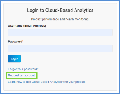
- Go to the CBA portal at https://insight.quantum.com.
- Click the Request an account link.
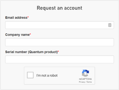
- Enter an Email address, Company name, and Serial number for your F1000, then select the I'm not a robot check box.
- Quantum will send an email with a user name and password to log in to the CBA portal.
- Verify you can view the information for this F1000 within your solution view on the CBA portal at https://insight.quantum.com.
Note: This applies to F-Series 1.x software ONLY. This does not apply to QBSP 2.x software.
- In the F-Series UI, select Miscellaneous in the left navigation menu.
- Click the CLOUD-BASED ANALYTICS tab.
- (Optional) Enter the Device Registration ID, as it displays in the CBA portal.
-
Log in to the CBA portal at https://insight.quantum.com with the user name and password for your CBA account.
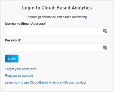
- Click Login. You will see your facility's name, followed by a Solutions section for one or more of your solutions that are monitored by CBA. Solutions may include multiple components that are grouped together under the solution name. For example, if you have multiple F1000 systems, they may be grouped together into a single F1000 "solution."
- In the Solutions section, click the solution that corresponds to your F1000. In some cases, this will bring up the Node names on the right side of the page, and you can skip to Step e. If not, continue to the next step.
- Scroll down the page to a section with the nodes for the F1000 solution listed.
- Click the Hostname link for the node you are currently configuring in the F-Series Manager.
-
In your browser's address bar, the device's CBA URL displays. As shown in the following example, the Device Registration ID (highlighted in green) is "3792".

- Enter this number for the Device Registration ID in the F-Series Manager.
- Click Apply to confirm the change.
Note: By default, the CBA link in the left menu of the F-Series Manager launches the generic CBA portal page: https://insight.quantum.com. However, if you have more than one F1000, or other Quantum CBA-supported hardware, you can configure this button to launch the CBA dashboard for this specific F1000 in the CBA portal.
Note: If your solution includes more than one device (such as additional F1000s or Xcellis Workflow Director systems), and you already received credentials for one of the systems, you can add another device to your account. Send an email to DL-Insight-Admin@quantum.com with information about your additional systems, and the CBA team will add additional devices to the CBA portal view for your account.
- Select Miscellaneous in the left navigation menu.
- Click the CLOUD-BASED ANALYTICS tab.
- Click the Enable Cloud-Based Analytics toggle to disable CBA. It turns gray, indicated it is disabled.
- Click Apply to confirm the change.
- In the F-Series UI, select Miscellaneous in the left navigation menu.
- Go to the CLOUD-BASED ANALYTICS tab.
- Click the Enable Cloud-Based Analytics toggle to disable CBA. It turns gray to indicate it is disabled.
- Click Apply to confirm the change.
This allows you to set an NTP time server for the F1000.
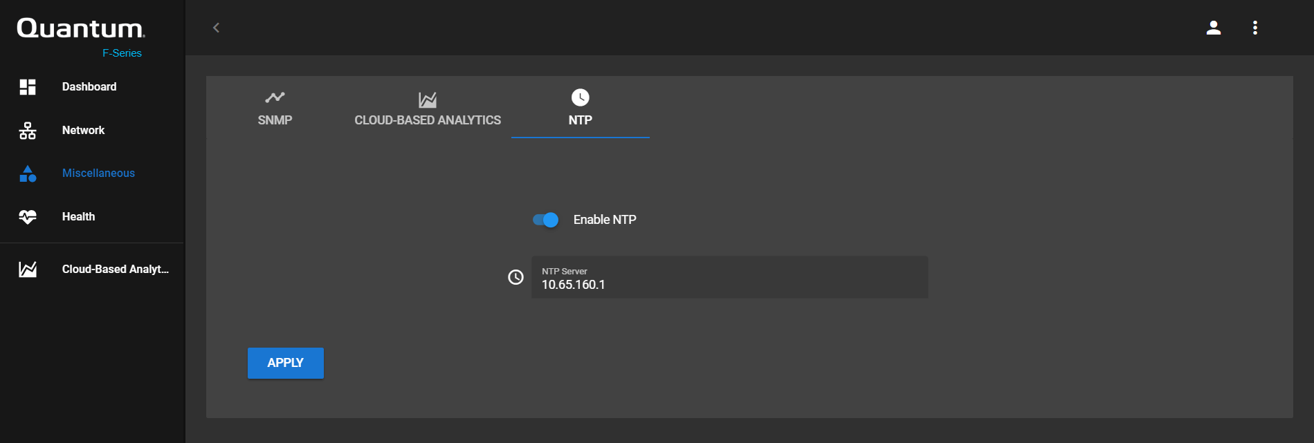
- In the F-Series UI, select Miscellaneous in the left navigation menu.
- Click the NTP tab.
- Click the Enable NTP toggle. It turns blue, indicating it is enabled.
- Enter an NTP Server address.
- Click Apply to confirm the change.
Example (NTP server name): time.nist.gov
Example (NTP server IP address): 129.6.15.28
- In the F-Series UI, select Miscellaneous in the left navigation menu.
- Click the NTP tab.
- Click the Enable NTP toggle. It turns gray, indicating it is disabled.
- Click Apply to confirm the change.
Note: This applies to F-Series 1.x software ONLY. This does not apply to QBSP 2.x software.
The BMC Web UI allows you to update the default admin user credentials and create additional users. The system can have up to ten users. Three types of users are available:
- User
- Operator
- Administrator
The table below details the privileges associated with each type of user.
| Type of User | |||
|---|---|---|---|
|
Function |
User |
Operator |
Administrator |
|
System Information |
Full access |
Full access |
Full access |
|
Chassis Locator Control |
View only |
Full access |
Full access |
|
FRU Reading |
Full access |
Full access |
Full access |
|
Sensor Readings |
Full access |
Full access |
Full access |
|
Event Log |
View only |
Full access |
Full access |
|
Alert |
None |
View only |
Full access |
|
LDAP |
None |
View only |
Full access |
|
Mouse Mode |
None |
Full access |
Full access |
|
Network |
None |
View only |
Full access |
|
SMTP |
None |
View only |
Full access |
|
SSL |
None |
View only |
Full access |
|
Users |
None |
View only |
Full access |
|
Event Action |
None |
View only |
Full access |
|
Power Control |
View only |
Full access |
Full access |
|
KVM |
View only |
Full access |
Full access |
|
F/W Update |
View only |
View only |
Full access |
|
Logout |
Full access |
Full access |
Full access |
Before you create users or change their settings, you must log into the BMC Web UI.
Access the BMC Web UI by completing the steps below.
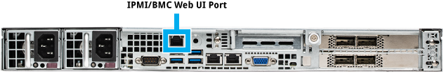
Use an Ethernet cable to connect a notebook computer to the IPMI/BMC port on the F1000.
Complete one of the following procedures, depending on whether you are using a Mac or Windows computer.
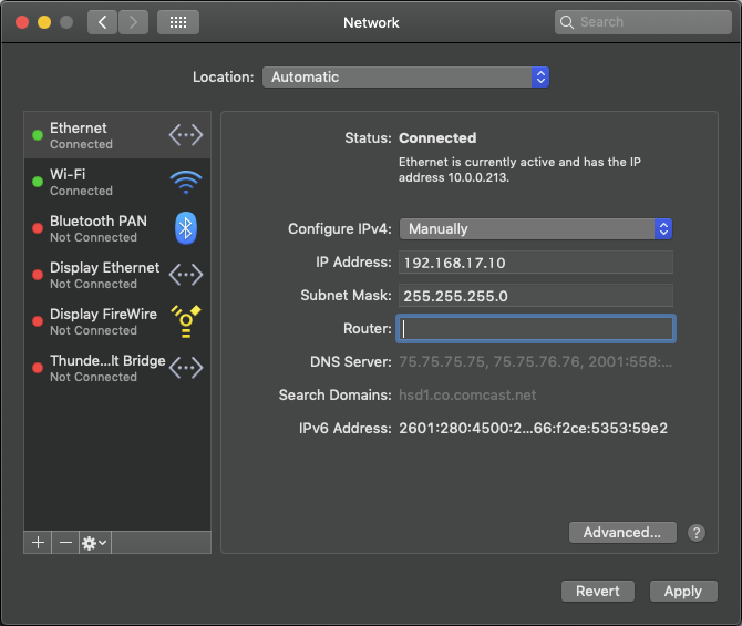
When you configure the IPv4 network settings for the Ethernet connection on the computer, you will access the system directly, while connected to the IPMI/BMC UI Port.
- IP Address - 192.168.17.10
- Subnet Mask - 255.255.255.0
Note: These steps may differ, depending upon your version of macOS.
- Click an open area of the Mac desktop, and select Apple menu > System Preferences > Network, or click System Preferences in the Dock.
- Click Network in System Preferences.
- Select the Ethernet connection in use.
- In the Configure IPv4 list, select Manually.
Quantum recommends writing down the settings in this dialog box before you change them. You can refer to this information later when you finish using this network connection, and you return the settings to their original values.
- Enter the IP address and subnet mask values (leave router blank):
- IP Address - 192.168.17.10
- Subnet Mask - 255.255.255.0
- Click Apply.
- Close the Network dialog.


Example (Mojave):
It may take a couple minutes to enable the network connection.
Note: The following steps may differ, depending on your version of Windows.
- Access the Network Connections dialog using one of the following methods:
- For Windows 10, right-click Start, click Network Connections, and click Change Adapter Options in the right pane of the dialog.
- For older Windows versions, click the Start menu, then search for and open the View Network Connections dialog.
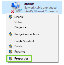
- Right-click the network connection that corresponds to the Ethernet port on the computer in use—for example, Ethernet or Local Area Connection—and select Properties.
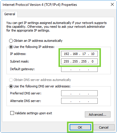
- From the list of connections, select Internet Protocol Version 4 (TCP/IPv4), then click Properties to display the Internet Protocol Version 4 (TCP/IPv4) Properties dialog box.
Note: Quantum recommends writing down the settings in this dialog box before you change them. You can refer to this information later when you finish using this network connection, and you set the settings back to their original values.
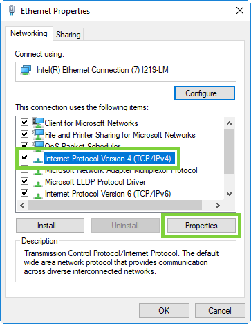
- Click Use the following IP address, and enter the appropriate IP address and Subnet mask values (leave gateway blank), then click OK.
- IP Address - 192.168.17.10
- Subnet Mask - 255.255.255.0
- Click Close.
It may take a couple minutes to enable the network connection.
-
On the notebook computer, open a supported Web browser, type https://192.168.17.21 in the address box, and press Enter.
Note: You must use “https://” the first time you access the BMC Web UI through the IPMI/BMC port.
The Login screen displays.
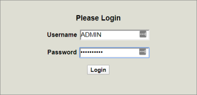
-
Log into the BMC Web UI. The default credentials are:
- Username: ADMIN
- Password: The series of alphanumeric characters included after "PWD" on the sticker on the top, left corner of the unit.
Sticker location:
Once logged in, the System page displays.
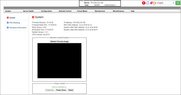
Using the BMC Web UI, you can complete the following tasks:
-
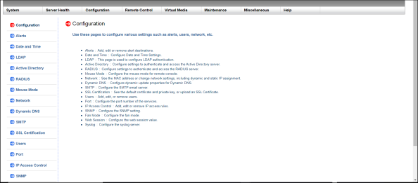
In the BMC Web UI, click Configuration in the Main Menu at the top of the page to open the Configuration page.
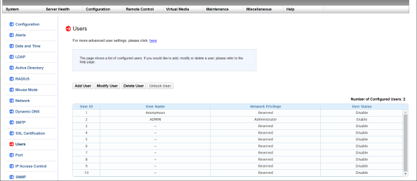
-
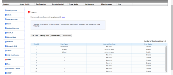
In the Submenu on the left, click Users to open the Users page.
-
Click the first empty row to highlight it; then click Add User.
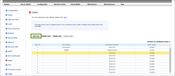
The Add New User page appears.
-
In the Add New User page, enter a User Name for the user.
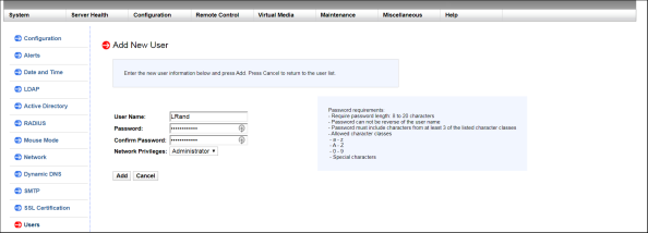
- Enter a Password for the user, then enter the same password in the Confirm Password field. Password parameters display on the right side of the page.
-
Select the Network Privileges for the new user from the list:
- Administrator
- Operator
- User
- Click Add. A confirmation message informs you the user was successfully added.
-
In the BMC Web UI, click Configuration in the Main Menu at the top of the page to open the Configuration page.
-
In the Submenu on the left, click Users to open the Users page.
-
Select the user that you want to modify, then click Modify User.
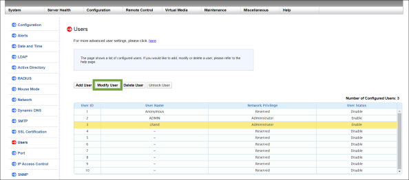
The Modify Users page appears.
-
In the Modify User page, you can change the user's password and network privileges.
- To change the user's password, select the Change Password check box, enter the new password, then confirm the new password by entering it again. Password parameters display on the right side of the page.
- To change the user's network privileges, select a new user type from the Network Privileges list.
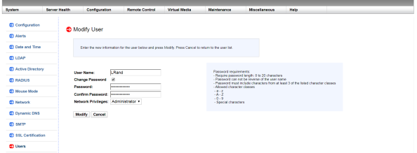
- After making your changes, click Modify to apply the changes, and return to the Users page.
-
In the BMC Web UI, click Configuration in the Main Menu at the top of the page to open the Configuration page.
-
In the Submenu on the left, click Users to open the Users page.
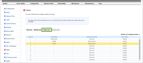
-
Select the user that you want to delete, then click Delete User.
-
A confirmation message asks if you want to delete the user; click Yes.
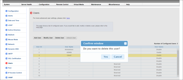
A confirmation message informs you that the user was deleted. The User page refreshes, and the user is no longer listed in the user grid.
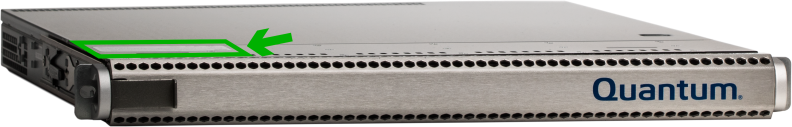
You may need to identify the F1000 when it is installed in a crowded data center rack. You can do this by turning on the blue unit identification (UID) LED on the front and back of the chassis. To do this, you can press the UID button on front of the chassis, or use the BMC Web UI.
Press the UID button on the front of the F1000 (see diagram below).
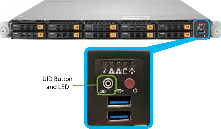
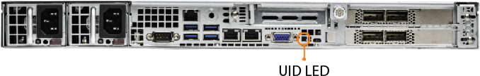
The UID LED illuminates on the front and back of the unit (see a diagram of the back of the F1000 below).
Note: This applies to F-Series 1.x software ONLY. This does not apply to QBSP 2.x software.
First, log into the BMC Web UI.
Access the BMC Web UI by completing the steps below.
Use an Ethernet cable to connect a notebook computer to the IPMI/BMC port on the F1000.
Complete one of the following procedures, depending on whether you are using a Mac or Windows computer.
When you configure the IPv4 network settings for the Ethernet connection on the computer, you will access the system directly, while connected to the IPMI/BMC UI Port.
- IP Address - 192.168.17.10
- Subnet Mask - 255.255.255.0
Note: These steps may differ, depending upon your version of macOS.
- Click an open area of the Mac desktop, and select Apple menu > System Preferences > Network, or click System Preferences in the Dock.
- Click Network in System Preferences.
- Select the Ethernet connection in use.
- In the Configure IPv4 list, select Manually.
Quantum recommends writing down the settings in this dialog box before you change them. You can refer to this information later when you finish using this network connection, and you return the settings to their original values.
- Enter the IP address and subnet mask values (leave router blank):
- IP Address - 192.168.17.10
- Subnet Mask - 255.255.255.0
- Click Apply.
- Close the Network dialog.
Example (Mojave):
It may take a couple minutes to enable the network connection.
Note: The following steps may differ, depending on your version of Windows.
- Access the Network Connections dialog using one of the following methods:
- For Windows 10, right-click Start, click Network Connections, and click Change Adapter Options in the right pane of the dialog.
- For older Windows versions, click the Start menu, then search for and open the View Network Connections dialog.
- Right-click the network connection that corresponds to the Ethernet port on the computer in use—for example, Ethernet or Local Area Connection—and select Properties.
- From the list of connections, select Internet Protocol Version 4 (TCP/IPv4), then click Properties to display the Internet Protocol Version 4 (TCP/IPv4) Properties dialog box.
Note: Quantum recommends writing down the settings in this dialog box before you change them. You can refer to this information later when you finish using this network connection, and you set the settings back to their original values.
- Click Use the following IP address, and enter the appropriate IP address and Subnet mask values (leave gateway blank), then click OK.
- IP Address - 192.168.17.10
- Subnet Mask - 255.255.255.0
- Click Close.
It may take a couple minutes to enable the network connection.
-
On the notebook computer, open a supported Web browser, type https://192.168.17.21 in the address box, and press Enter.
Note: You must use “https://” the first time you access the BMC Web UI through the IPMI/BMC port.
The Login screen displays.
-
Log into the BMC Web UI. The default credentials are:
- Username: ADMIN
- Password: The series of alphanumeric characters included after "PWD" on the sticker on the top, left corner of the unit.
Sticker location:
Once logged in, the System page displays.
Second, use the BMC Web UI to illuminate the UID LEDs.
-
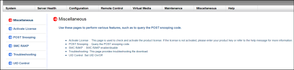
In the BMC Web UI, click Miscellaneous in the Main Menu at the top of the page to open the Miscellaneous page.
-
In the Submenu on the left, click UID Control to open the UID Control page.
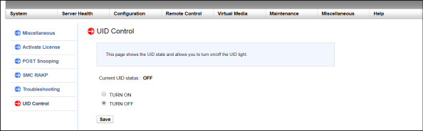
-
Select TURN ON, then click Save.
A confirmation message notifies you the UID setting was saved.
The UID LED illuminates on the front and back of the F1000.
It also illuminates on the back of the F1000.
Note: This applies to F-Series 1.x software ONLY. This does not apply to QBSP 2.x software.
You can check the status of the system components any time. Monitored system components include:
- Fans
- Power supply
- Physical security
- Temperatures:
- CPU
- System
- Peripheral
- LAN
- DIMM
- NVMe SSD
To check the status of system components:
- Access the BMC Web UI:
- IP Address - 192.168.17.10
- Subnet Mask - 255.255.255.0
- Click an open area of the Mac desktop, and select Apple menu > System Preferences > Network, or click System Preferences in the Dock.
- Click Network in System Preferences.
- Select the Ethernet connection in use.
- In the Configure IPv4 list, select Manually.
Quantum recommends writing down the settings in this dialog box before you change them. You can refer to this information later when you finish using this network connection, and you return the settings to their original values.
- Enter the IP address and subnet mask values (leave router blank):
- IP Address - 192.168.17.10
- Subnet Mask - 255.255.255.0
- Click Apply.
- Close the Network dialog.
- Access the Network Connections dialog using one of the following methods:
- For Windows 10, right-click Start, click Network Connections, and click Change Adapter Options in the right pane of the dialog.
- For older Windows versions, click the Start menu, then search for and open the View Network Connections dialog.
- Right-click the network connection that corresponds to the Ethernet port on the computer in use—for example, Ethernet or Local Area Connection—and select Properties.
- From the list of connections, select Internet Protocol Version 4 (TCP/IPv4), then click Properties to display the Internet Protocol Version 4 (TCP/IPv4) Properties dialog box.
Note: Quantum recommends writing down the settings in this dialog box before you change them. You can refer to this information later when you finish using this network connection, and you set the settings back to their original values.
- Click Use the following IP address, and enter the appropriate IP address and Subnet mask values (leave gateway blank), then click OK.
- IP Address - 192.168.17.10
- Subnet Mask - 255.255.255.0
- Click Close.
-
On the notebook computer, open a supported Web browser, type https://192.168.17.21 in the address box, and press Enter.
Note: You must use “https://” the first time you access the BMC Web UI through the IPMI/BMC port.
The Login screen displays.
-
Log into the BMC Web UI. The default credentials are:
- Username: ADMIN
- Password: The series of alphanumeric characters included after "PWD" on the sticker on the top, left corner of the unit.
Sticker location:
Once logged in, the System page displays.
-
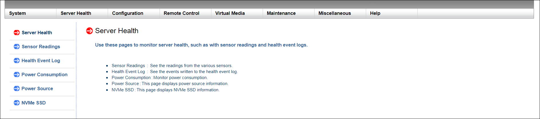
Click Server Health in the Main Menu at the top of the page to open the Server Health page.
-
In the Submenu on the left, click Sensor Readings to open the Sensor Readings page.
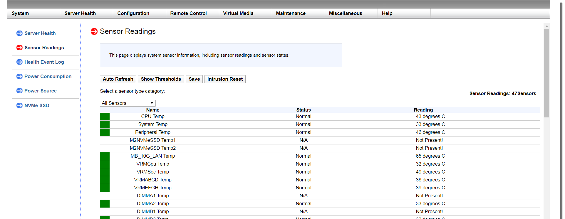
- Check the state of the components.
Use an Ethernet cable to connect a notebook computer to the IPMI/BMC port on the F1000.
Complete one of the following procedures, depending on whether you are using a Mac or Windows computer.
When you configure the IPv4 network settings for the Ethernet connection on the computer, you will access the system directly, while connected to the IPMI/BMC UI Port.
Note: These steps may differ, depending upon your version of macOS.
Example (Mojave):
It may take a couple minutes to enable the network connection.
Note: The following steps may differ, depending on your version of Windows.
It may take a couple minutes to enable the network connection.
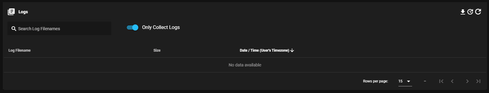
To download the system logs:
-
In the top navigation of the UI, click Logs to display the Logs page.
-
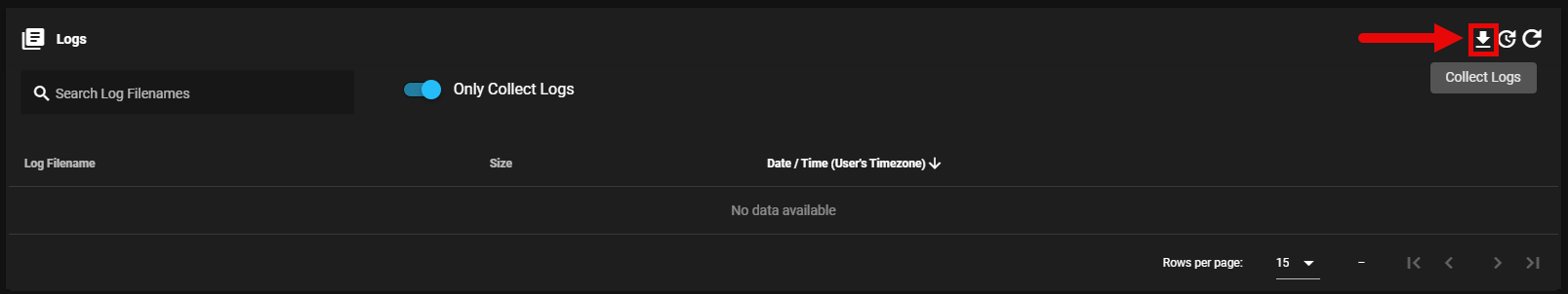
In the Logs page, click Collect Logs.
-
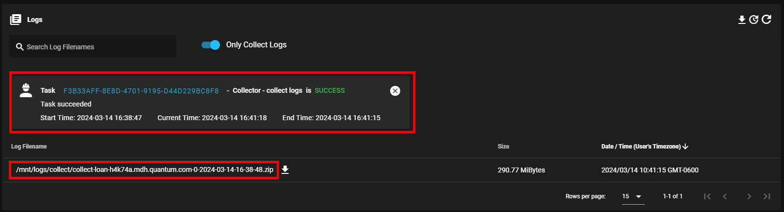
The log collection process begins. Verify the logs are collected successfully; the corresponding task is completed successfully and its log file bundle (.zip) appears in the table.
-
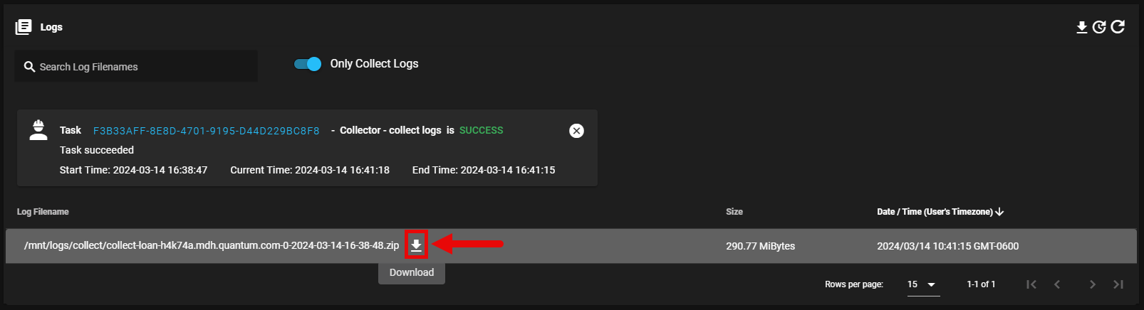
Click Download to save the log file bundle (.zip) to a local destination.
Note: This applies to F-Series 1.x software ONLY. This does not apply to QBSP 2.x software.
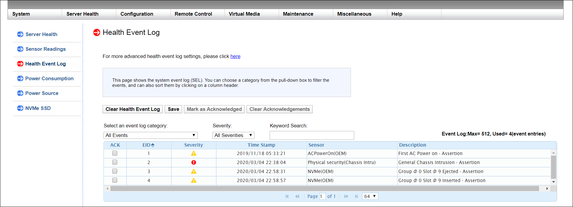
If you contact Quantum Technical Support for help, they may request that you download and provide the Health Event Log for the F1000.
The Health Event Log indicates when a critical condition occurred, and when this condition was resolved. You can also filter the log for specific information.
To access and download the Health Event Log:
- Access the BMC Web UI:
- IP Address - 192.168.17.10
- Subnet Mask - 255.255.255.0
- Click an open area of the Mac desktop, and select Apple menu > System Preferences > Network, or click System Preferences in the Dock.
- Click Network in System Preferences.
- Select the Ethernet connection in use.
- In the Configure IPv4 list, select Manually.
Quantum recommends writing down the settings in this dialog box before you change them. You can refer to this information later when you finish using this network connection, and you return the settings to their original values.
- Enter the IP address and subnet mask values (leave router blank):
- IP Address - 192.168.17.10
- Subnet Mask - 255.255.255.0
- Click Apply.
- Close the Network dialog.
- Access the Network Connections dialog using one of the following methods:
- For Windows 10, right-click Start, click Network Connections, and click Change Adapter Options in the right pane of the dialog.
- For older Windows versions, click the Start menu, then search for and open the View Network Connections dialog.
- Right-click the network connection that corresponds to the Ethernet port on the computer in use—for example, Ethernet or Local Area Connection—and select Properties.
- From the list of connections, select Internet Protocol Version 4 (TCP/IPv4), then click Properties to display the Internet Protocol Version 4 (TCP/IPv4) Properties dialog box.
Note: Quantum recommends writing down the settings in this dialog box before you change them. You can refer to this information later when you finish using this network connection, and you set the settings back to their original values.
- Click Use the following IP address, and enter the appropriate IP address and Subnet mask values (leave gateway blank), then click OK.
- IP Address - 192.168.17.10
- Subnet Mask - 255.255.255.0
- Click Close.
-
On the notebook computer, open a supported Web browser, type https://192.168.17.21 in the address box, and press Enter.
Note: You must use “https://” the first time you access the BMC Web UI through the IPMI/BMC port.
The Login screen displays.
-
Log into the BMC Web UI. The default credentials are:
- Username: ADMIN
- Password: The series of alphanumeric characters included after "PWD" on the sticker on the top, left corner of the unit.
Sticker location:
Once logged in, the System page displays.
-
In the BMC Web UI, click Server Health in the Main Menu at the top of the page to open the Server Health page.
-
In the Submenu on the left, click Health Event Log to open the Health Event Log page. You can sort the data by column header, if needed.
-
You can filter log data by specifying the criteria below. Boot up and shutdown events also display.
- Event Log Category: Select an event type from the list to display in the log:
- Senor-specific
- UEFI BIOS-generated
- System Management and Software
- All
-
Severity: Select a severity type from the list to display in the log. Severities are outlined in the table below.
Severity
Icon
Critical

Warning

Information

Acknowledged
N/A
All
N/A
- Keyword Search: Enter a word or a phrase to display in the log.
- Event Log Category: Select an event type from the list to display in the log:
-
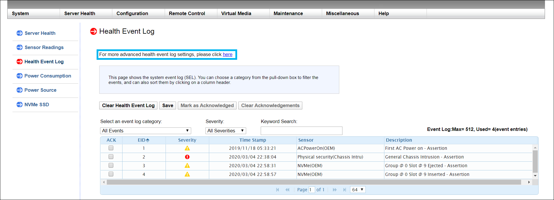
If you want to include AC Power On and FIFO events in the event log, complete the following steps:
-
Click the here link in the advanced settings statement at the top of the page.
-
Select the check boxes for the events that you want to display in the log.
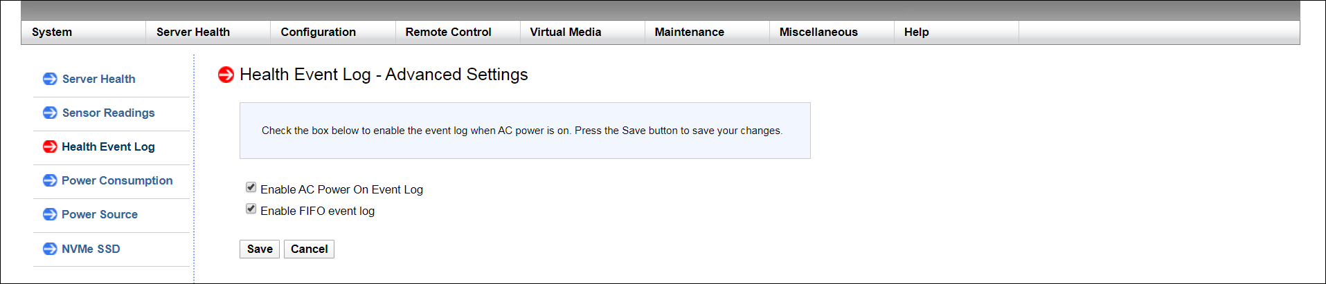
- Click Save.
-
- If needed, click Save to download the log as a .CSV file. The file will be called "event.csv."
Use an Ethernet cable to connect a notebook computer to the IPMI/BMC port on the F1000.
Complete one of the following procedures, depending on whether you are using a Mac or Windows computer.
When you configure the IPv4 network settings for the Ethernet connection on the computer, you will access the system directly, while connected to the IPMI/BMC UI Port.
Note: These steps may differ, depending upon your version of macOS.
Example (Mojave):
It may take a couple minutes to enable the network connection.
Note: The following steps may differ, depending on your version of Windows.
It may take a couple minutes to enable the network connection.
The Maintenance Event Log identifies who accessed the BMC Web UI, and the function the user performed. For example, each time a user logs into the BMC Web UI, the system saves the following:
- The severity of the action the user performed (critical, warning, or information)
- The date and time the user accessed the system
- The interface the user used to access the system
- The user's name
- The source that triggered the event
- The action the user performed
You can download the Maintenance Event Log. You can also disable it, so that users cannot clear or save it.
To access and download the Maintenance Event Log:
- Access the BMC Web UI for the system.
- IP Address - 192.168.17.10
- Subnet Mask - 255.255.255.0
- Click an open area of the Mac desktop, and select Apple menu > System Preferences > Network, or click System Preferences in the Dock.
- Click Network in System Preferences.
- Select the Ethernet connection in use.
- In the Configure IPv4 list, select Manually.
Quantum recommends writing down the settings in this dialog box before you change them. You can refer to this information later when you finish using this network connection, and you return the settings to their original values.
- Enter the IP address and subnet mask values (leave router blank):
- IP Address - 192.168.17.10
- Subnet Mask - 255.255.255.0
- Click Apply.
- Close the Network dialog.
- Access the Network Connections dialog using one of the following methods:
- For Windows 10, right-click Start, click Network Connections, and click Change Adapter Options in the right pane of the dialog.
- For older Windows versions, click the Start menu, then search for and open the View Network Connections dialog.
- Right-click the network connection that corresponds to the Ethernet port on the computer in use—for example, Ethernet or Local Area Connection—and select Properties.
- From the list of connections, select Internet Protocol Version 4 (TCP/IPv4), then click Properties to display the Internet Protocol Version 4 (TCP/IPv4) Properties dialog box.
Note: Quantum recommends writing down the settings in this dialog box before you change them. You can refer to this information later when you finish using this network connection, and you set the settings back to their original values.
- Click Use the following IP address, and enter the appropriate IP address and Subnet mask values (leave gateway blank), then click OK.
- IP Address - 192.168.17.10
- Subnet Mask - 255.255.255.0
- Click Close.
-
On the notebook computer, open a supported Web browser, type https://192.168.17.21 in the address box, and press Enter.
Note: You must use “https://” the first time you access the BMC Web UI through the IPMI/BMC port.
The Login screen displays.
-
Log into the BMC Web UI. The default credentials are:
- Username: ADMIN
- Password: The series of alphanumeric characters included after "PWD" on the sticker on the top, left corner of the unit.
Sticker location:
Once logged in, the System page displays.
-
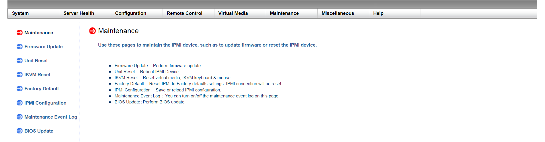
In the BMC Web UI, click Maintenance in the Main Menu at the top of the page to open the Maintenance page.
-
In the Submenu on the left, click Maintenance Event Log to open the Maintenance Event Log page. You can sort the data by column header, in needed.
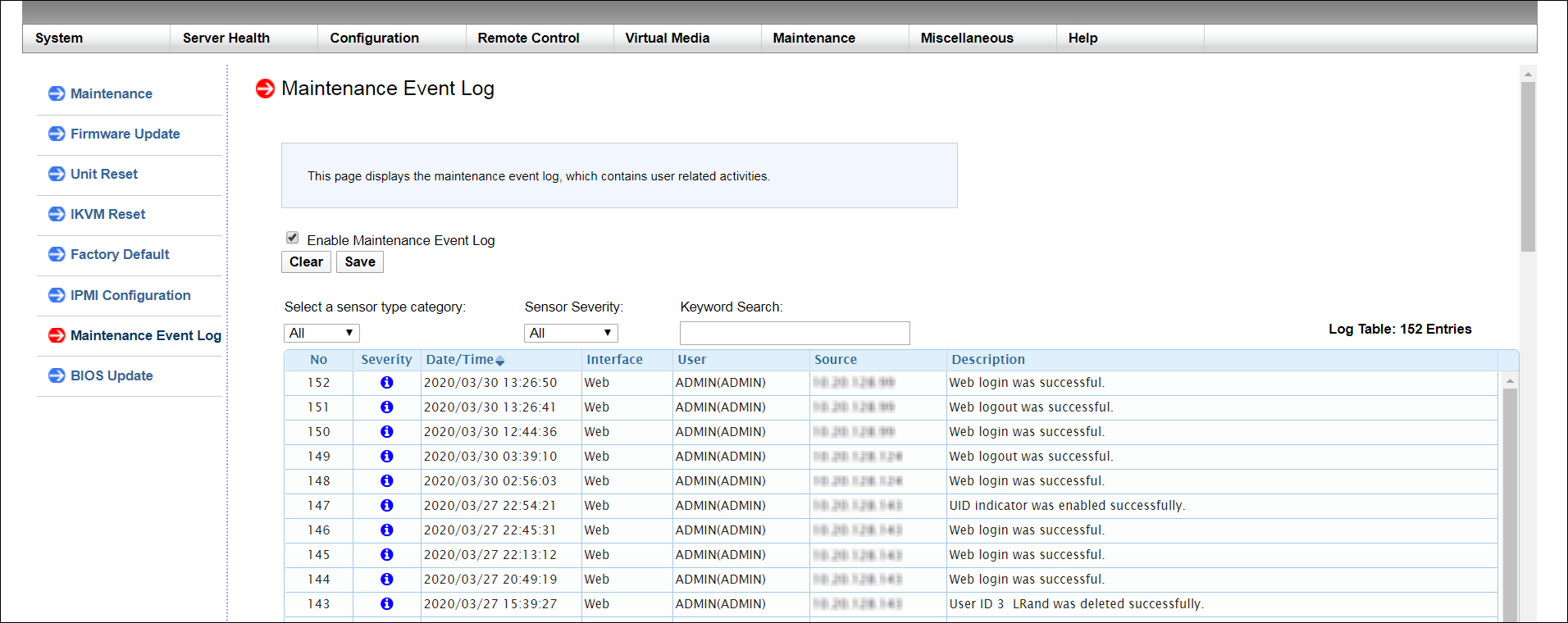
- You can filter log data by specifying criteria below.
- Sensor Type Category: Select a sensor type from the list to display in the log:
- Storage
- Account
- Network
- Service
- Others
Sensor Severity: Select a severity type from the list to display in the log. Severities are outlined in the table below.
Severity
Icon
Critical
Warning
Information
- Keyword Search: Enter a word or phrase to display in the log.
- Sensor Type Category: Select a sensor type from the list to display in the log:
-
To disable the Maintenance Event Log—which disallows users from clearing or saving the log—clear the Enable Maintenance Event Log check box. A confirmation message notifies you that the configuration was set.
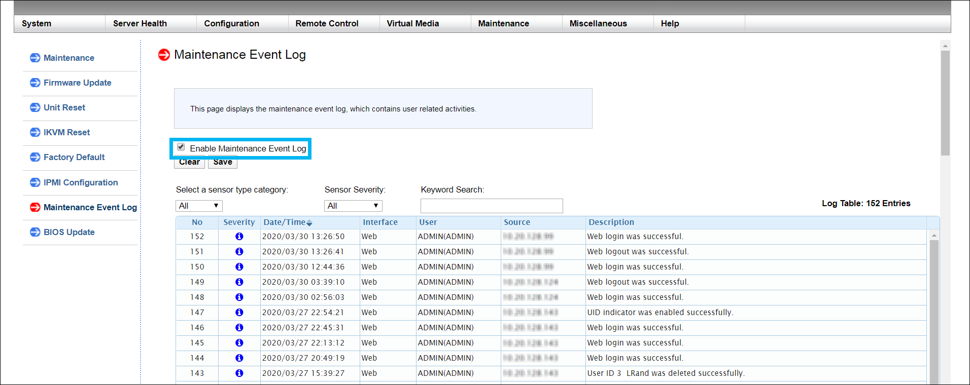
- If needed, click Save to download the log as a CSV file. The file will be called "system_event.csv."
Use an Ethernet cable to connect a notebook computer to the IPMI/BMC port on the F1000.
Complete one of the following procedures, depending on whether you are using a Mac or Windows computer.
When you configure the IPv4 network settings for the Ethernet connection on the computer, you will access the system directly, while connected to the IPMI/BMC UI Port.
Note: These steps may differ, depending upon your version of macOS.
Example (Mojave):
It may take a couple minutes to enable the network connection.
Note: The following steps may differ, depending on your version of Windows.
It may take a couple minutes to enable the network connection.
If you contact Quantum Technical Support for help, they may request that you download and provide the Support Bundle for the F1000 from the QCSP (Quantum Cloud Storage Platform) TUI.
You will need the following tools to create and download an F1000 Support Bundle:
PuTTY (or similar SSH tool)
WinSCP (or similar tool)
To create and download the Support Bundle:
-
Access the QCSP TUI:
 Access the Command Line and QCSP TUI
- On a laptop, open an SSH session to the command line of the system using the management IP address of the F1000.
- Log in to the command line:
Username: root
Password: <password>
- Launch the Quantum Cloud Storage Platform TUI. Enter:
/usr/local/bin/esos_tuiThe Quantum Cloud Storage Platform TUI screen appears:
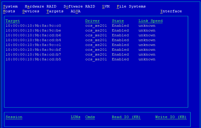
- Press the I key to display the Interface menu:
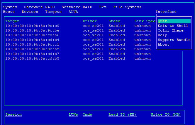
- Use the Down Arrow key to select Support Bundle. Press Enter to create the support bundle.
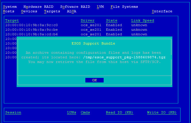
The ESOS Support Bundle dialog box displays, notifiying you that the support bundle was created.
- Note the support bundle's name and location. Then, press Enter to indicate OK, and close the ESOS Support Bundle dialog box.
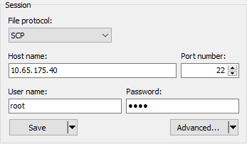
- Using WinSCP or a similar tool, retrieve the support bundle. To create a new WinSCP site, enter:
- File protocol: SCP
- Host name: The management IP address for the system
- User name: root
- Password: The default password is “esos”. This should have changed during installation.
Example:
-
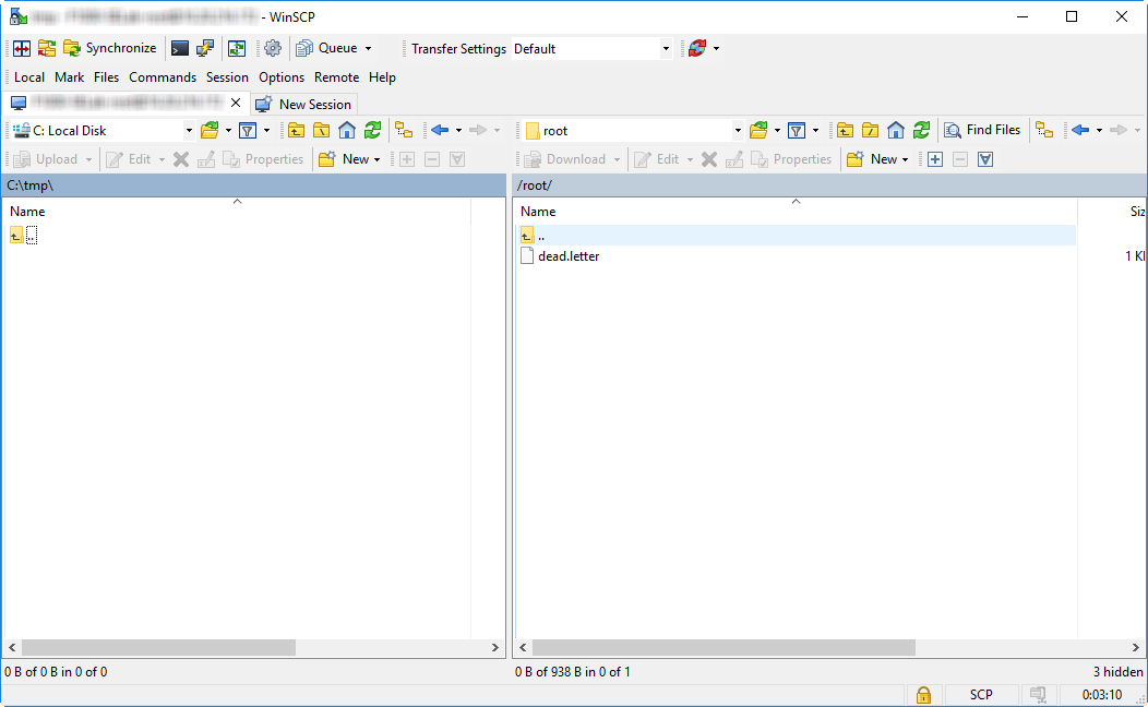
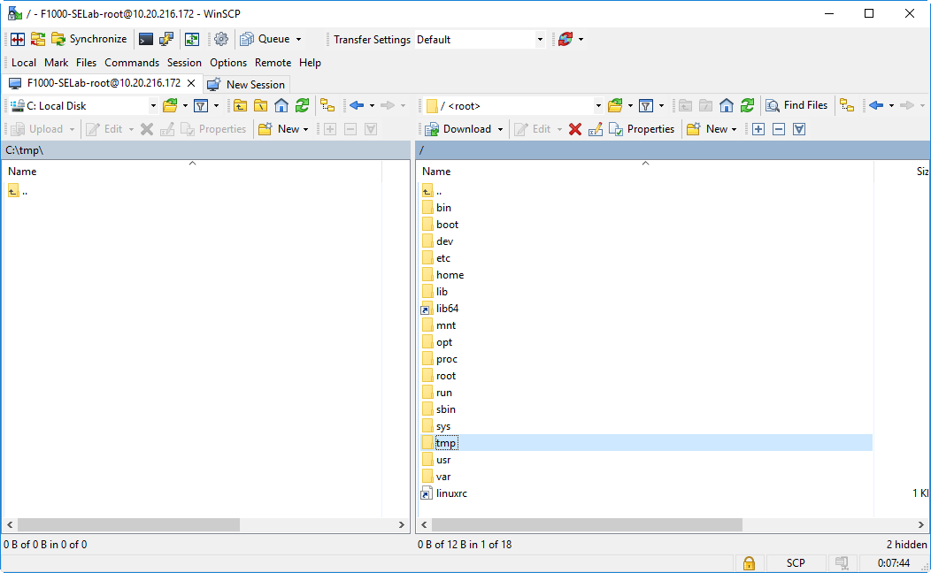
For WinSCP, click Login to see your local directory on the left, and an F1000 directory on the right:
-
In the right pane of the WinSCP screen, click root directory to access to the root-level directory folder.
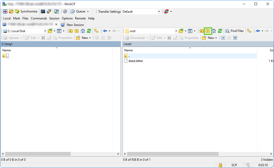
- Double-click the tmp directory:
-
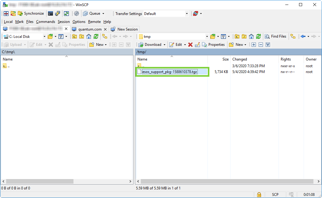
Locate the support bundle file. It will have a file name similar to "esos_support_pkg-xxxxxxxxxx.tgz."
-
Click-drag the file to a directory on your local system directory (left panel) to download the file to that directory:
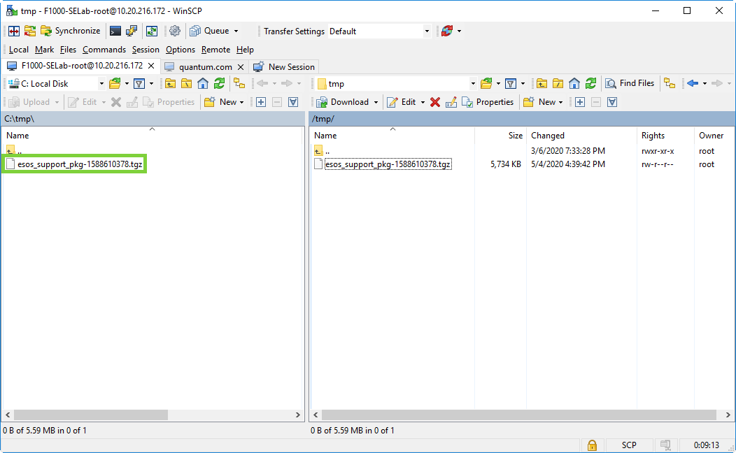
Alternately, right-click the file name, and select Download to open the Download window.
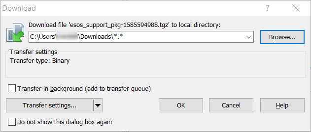
- Browse to a location on your computer to save the file, then click OK to transfer the file.
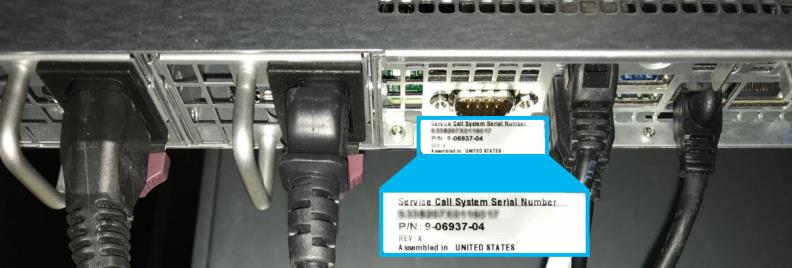
You will need your F1000 system serial number when you contact Quantum Technical Support. Use one of the following methods to locate the system serial number:
The system serial number is located on a sticker on the back of the F1000 system.
To locate the system serial number in the F-Series UI:
-
Log in to the F-Series UI.
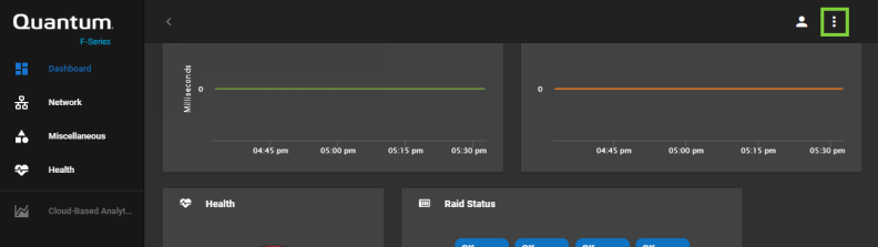
- Click System Options in the upper-right corner.
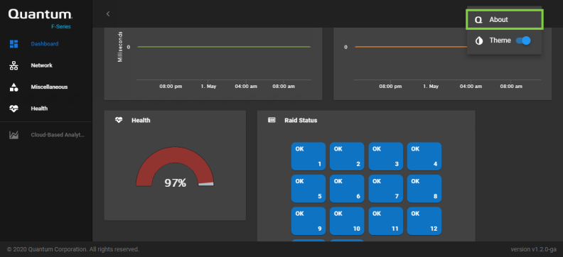
- Click About.
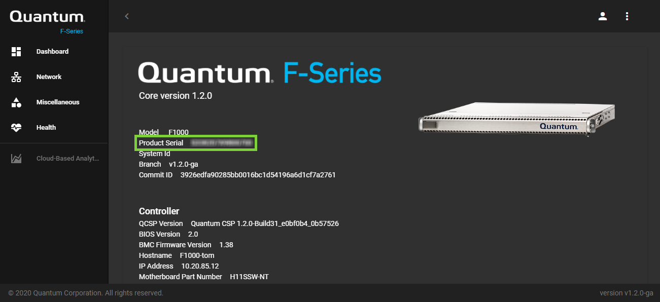
- The serial number displays as Product Serial.