Replace an i6H Expansion Module (EM) Chassis
This procedure replaces an existing Expansion Module (EM) chassis with a new EM chassis.
Tool Requirements
Removing an i6H library module requires the following tools:
-
T8 Torx wrench
-
T10 Torx wrench
-
T25 Torx wrench
Before You Begin
Before you begin the removal procedure, take a snapshot of the library and save your library configuration.
Your library has many configurable items, such as tape drive IDs, partitions, user accounts, Import/Export (I/E) slots, and cleaning slots. The Save/Restore window allows you to save your library's configuration and then restore the library’s firmware and configurable items to a previous state in the event of a hardware failure or firmware upgrade.
Restore a Configuration on the same Library
Before you restore a library configuration, review the following:
- If you have Logical System Addressing (LSA) enabled on the library, the saved configuration is specific to that library only. Do not attempt to clone the configuration to a different library.
- The library must have all the proper licenses installed before restoring a configuration.
Restore a Configuration on a new Library
Before you restore a library configuration, review the following:
- If you have LSA enabled and want to clone the configuration to a new library, you must first disable LSA and save the configuration (see Library Settings).
- If you want to clone a saved configuration to another library, you should only use the saved configuration upon initial installation of a new library. Once a the cloned configuration is on a new library, you should save a configuration specific to that new library.
- If you are cloning a saved configuration to a new library, the new library must have the same minimum license configuration as the library where the saved configuration came from.
- If you are cloning a saved configuration to a new library, the new library must have at least the same minimum module configuration. For example, if the library the saved configuration came from has 4 modules, the new library must have a least 4 or more modules.
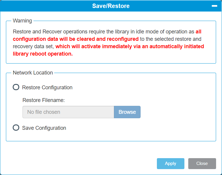
| Item | Description | Action |
|---|---|---|
| Restore Configuration |
Restores library to the selected configuration. After the restore, the library will automatically reboot. |
Select the radio button. |
| Restore Filename | Allows you to select the name of the library configuration file you want to restore. | Click the Browse button and navigate to the configuration file you want to use. Click Apply to begin restoring the library configuration. |
| Save Configuration | Saves the current library configuration. | Select the radio button. Click Apply. The library configuration file is downloaded. You can then use the file locally or email it. |
Click Close to exit the window.
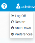
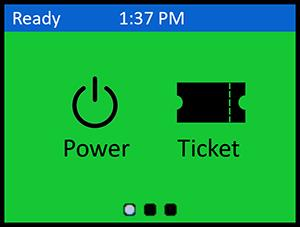
There are two (2) ways for you to power off your library:
Select Shut Down from the admin menu on the Menu Bar.
Navigate to Power > Shutdown
Remove the Expansion Module (EM) Chassis
To remove the robot, you must remove the Service Tray from the Control Service Module (CSM).
-
On the front of the CSM, open the left and right Service Tray Access Doors.
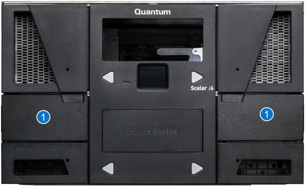
Item Name Description 1
Service Tray Access Doors Access to the override button and paddle that controls the buttons and paddles of the Service Tray receive and capture features. -
Verify that blue paddles in both the left and right service tray access panels are in the Captured position.
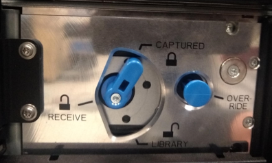
If both paddles are not in the Captured position, go to step 3.
If both paddles are in the Captured position, go to step 4.
-
Depress the Service Override button while rotating the paddle to the Captured position. Repeat this step in the other Service Tray Access panel.
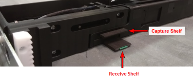
Caution: If the paddle does turn freely by hand is should not be forced. This typically implies the robot is not in a proper position. Forcing the paddle can cause damage to the Service Tray.
Note: If the paddle does not rotate to the Captured position, the robot is not fully seated on the Catch Shelves.
-
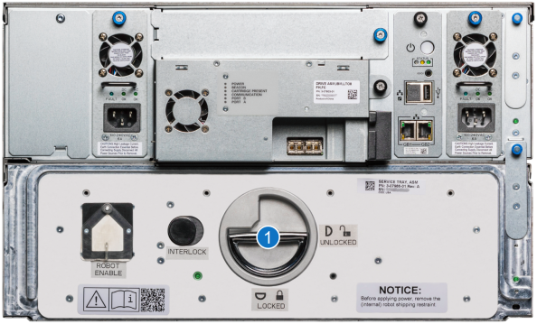
Remove the Service Tray. To unlock the Service Tray from the CSM, press the Interlock button. With the Interlock button pushed, lift the Service Tray Release Latch up and rotate it 90 degrees counterclockwise.
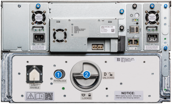
Item Name Description 1 Interlock Button Push the Interlock button while rotating the Service Tray Release Latch. 2 Service Tray Release Latch Rotate 90 degrees counterclockwise to the Unlocked postiion. -
Pull on the Service Tray Release Latch to remove the Service Tray from the CSM. When handling the Service Tray, use the blue handles and keep the tray level to avoid any damage to the tray.
Handling the Robot Service Tray
To properly handle the Service Tray outside of the library, Quantum recommends the following:
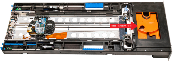
-
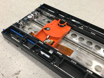
Place the Robot Shipping Restraint on the Robot Picker when handling the Service Tray. This will prevent excessive movement and damage to the Robot Picker.
Note: When restrained, the robot picker must aligned over the reach assembly in the location below.
-
Use the blue handles on the Service Tray when handling the Service Tray.
Item Name Description 1 Service Tray Handles Use handles when lifting and moving Service Tray. -
Keep the Service Tray horizontally flat. Handling the Service Tray vertically or at an angle may cause damage to tray components.
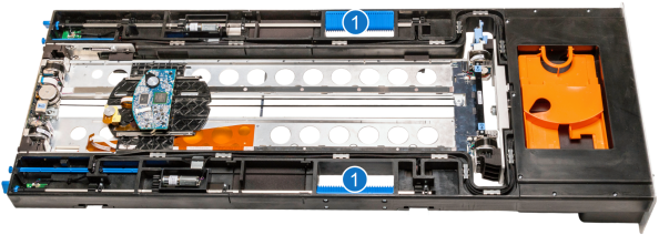
Important Information
-
When the Service Tray is out of the library, do not touch the toothed belt that drives the robot picker mechanism. The belt is under low spring tension and is not designed to withstand direct intentional or unintentional handling.
-
When the Service Tray is out of the library, do not touch robot ribbon cable . The cable tether and orange cable guide are not designed to withstand direct intentional or unintentional handling. If the cable tether gets folded, creased, or bent in manner that is not part of normal robotic operation, the cable can take a permanent set that can later interfere with automatic robot operation.
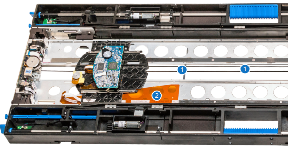
| Item | Name |
|---|---|
| 1 | Robot Picker Belt |
| 2 | Robot Ribbon Cable |
Important Information
Follow Steps 2 - 9 below for each module before removing the next module.
Mark or take a picture of all the magazines, drives, and cable in the module so you can correctly return everything to where it belongs.
If the module you are removing has drives and power supplies, do the following:
- Disconnect the power cables from power supplies.
- Disconnect the SAS or Fibre channel cables from the drives.
You will need to remove the components from each module that will need to be removed from the library to access the module that will be replaced.
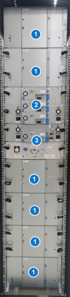
There are three different type of module configurations. Follow the module component instructions below.
Note: The library configuration below is an example. The library EM and drive configuration is different for each hyperscaler customer.
|
|
|
- Insert the T8 end of the assembly tool into the magazine release hole until the magazine pops out. Remove the magazine.
-
Remove any Drive Bay Storage (DBS) magazines by loosening the thumb screw on the rear of the module.
-
After the thumbscrew is loose, insert a T8 into the slot below and push up to release from the chassis.
- Loosen the thumbscrew.
- Pull the handle and slide the power supply out of the module.

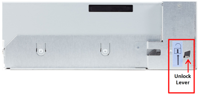
-
Loosen the drive thumbscrew.
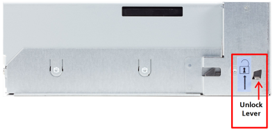
-
On the left side of the drive sled, press the lock lever up and slide the drive out of the drive bay.
- Pull out on the pins and slide the module interconnect down.
Select the appropriate procedure for the module that you are removing:
Front Attachments
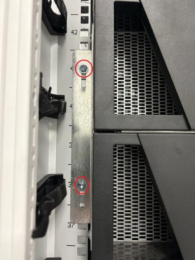
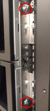
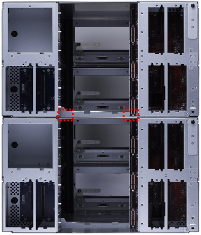
-
Remove the two (2) long screws in the holes at the front of the module in the magazine bays using a T10 Torx wrench.
Expansion Module - Rear Attachments
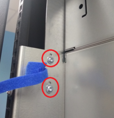
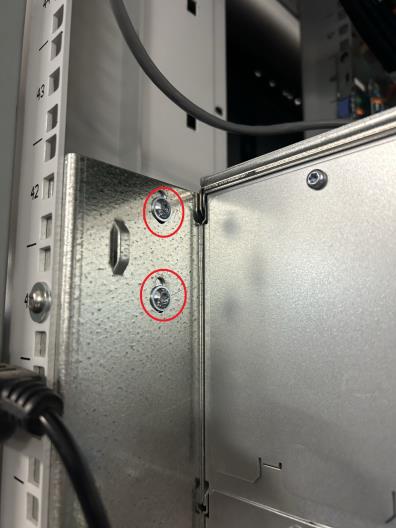
-
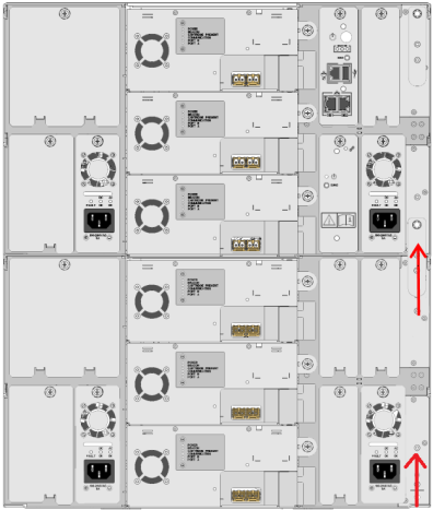
Remove the two (2) short screws in the holes at the back of the module in the drive bay using a T10 Torx wrench.
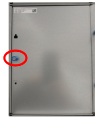
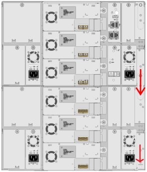
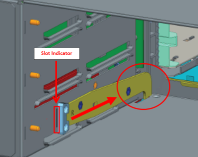
-
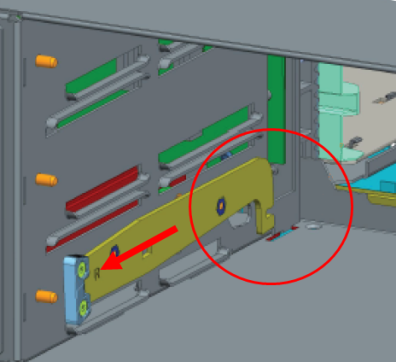
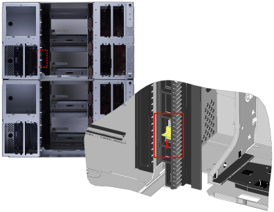
There are two latches on the left and right rear of the chassis. To unlock, pull the latch back until it disengages from the rear catch and the slot indicator on the side frame no longer appears.
Note: The Control Service Module (CSM) does not have rear latches.
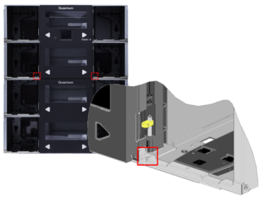
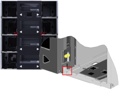
-
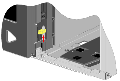
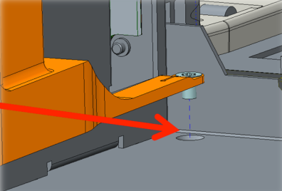
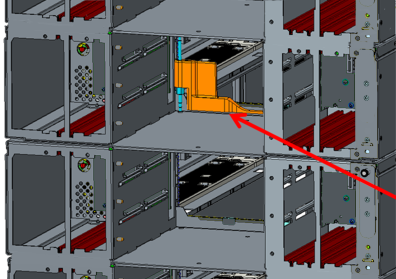
Find the tab at the front of the module and slide the front alignment pin up out of the hole on the module below.
-
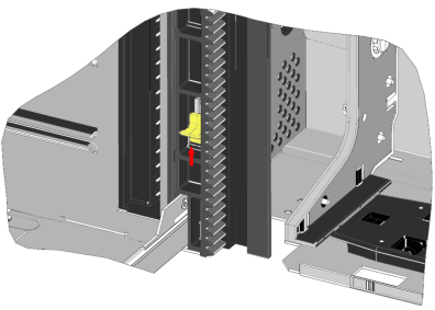
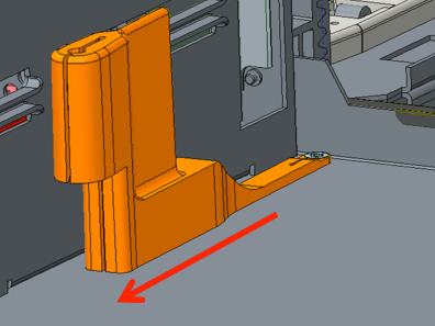
Find the tab at the back of the module and slide the back alignment pin up out of the hole on the module below.
There are two different types of racks currently used in i6H hyperscalers: APC and Rittal. Microsoft Azure uses the Rittal rack. All other hyperscalers use the APC rack.
Select from the following:
Detach Front of Module
Note: The top EM in the library stack is not attached to the rack. If you are removing the top EM, go to Detach Rear Bracket below.
Use a T25 torx wrench to loosen the two screws that attaches the module bracket to the rack. Repeat for the bracket on the other side of the module.
Detach Rear Bracket
The rear module contains a rear bracket at the top of the library stack that must be loosened before the modules can be removed.
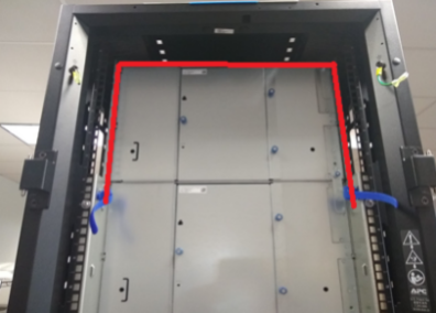
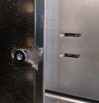
-
Use a T25 torx wrench to loosen the two screws at the bottom of the bracket.
-
Push up on the bracket so it clears the top of the top module and tighten the screws. Repeat this procedure on the other side of the bracket.
Detach Front of Module
Use a T25 torx wrench to loosen the two screws that attaches the module bracket to the rack. Repeat for the bracket on the other side of the module.
Detach Rear Bracket
The rear module contains a rear bracket at the top of the library stack that must be loosened before the modules can be removed.
-
Use a T25 torx wrench to loosen the two screws at the bottom of the bracket.
-
Push up on the bracket so it clears the top of the top module and tighten the screws. Repeat this procedure on the other side of the bracket.
Note: If the networking equipment above the module prevents the bracket from clearing the top of the module, you will need to remove the networking equipment from the rack.

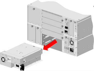
Using two (2) people, slide the module out of the rack and set on a flat surface.
Install the New Expansion Module (EM) Chassis
Each module comes in its own box. Any drives and redundant power supplies will come in separate boxes.
- Remove all packing materials. Retain these materials in case you need to ship your library in the future.
- With another person, carefully remove the module and place it on a work space.
- Remove all plastic covering.
- Remove drive bay covers from the back of the module.
If the new EM does not have front rack brackets, unscrew the brackets from the old EM and install on the new EM.
Important Information
Follow Steps 2 - 11 for each module before installing the next module. Failure to do this may cause alignment issues with the library stack
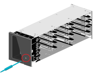
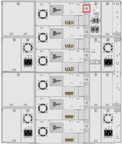
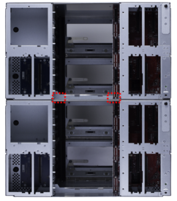
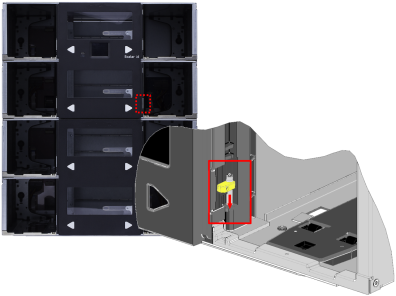
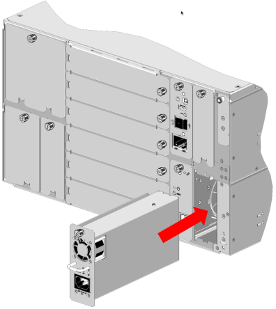
-
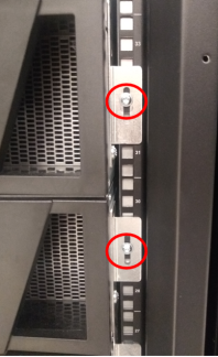
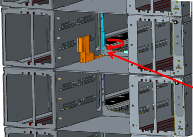
Place the module on top of the previously placed module and slid the module into the rack. The raised screws on the rear of the chassis should slid into the slots shown below.
-
Align the module with the module below by eye
-
Using the tab highlighted below, slide the front alignment pin down into the hole on the module below.
-
Using the tab, slide the rear alignment pin down into the hole on the module.
-
Pull out on the pins and slide the module interconnect up.
-
To attach the module to the module below, use the two (2) long screws in the holes at the front of the module in the magazine bays.
Caution: Tighten using the Torx. Do not use the torque wrench.
- To attach the module to the module below, use the two (2) short screws in the holes at the back of the module in the drive bay
-
Insert a short screw into the screw holder on the assembly tool.
-
Use the screw holder and the assembly tool torx wrench to get the rear screws started.
-
Pull straight back on the tool to release the screw.
-
Tighten the screw until you hear a click, or until you feel the torx wrench slip in the torque wrench. When it clicks or slips, the screw is torqued to 10 inch pounds.
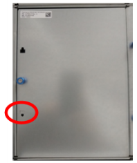
-
There are latches on the left and right rear of the chassis. To lock, push the latch forward until it moves down and engages the catch. A slot indicator on the side frame will also appear behind the latch when it is fully engaged into the catch.
Note: The Control Service Module (CSM) does not have rear latches.
Attach Front of Module
Note: The top EM in the library stack is not attached to the rack. If you are attaching the top EM, go to Attach Rear Bracket below.
Use a T25 torx wrench to tighten the two screws that attaches the module bracket to the rack. Repeat for the bracket on the other side of the module.
Attach Rear Bracket
The rear module contains a rear bracket at the top of the library stack that must attached into place.
-
Push down on the bracket so it engages the top of the top module.
-
Use a T25 torx wrench to tighten the two screws at the bottom of the bracket.
Attach Front of Module
Note: The top EM in the library stack is not attached to the rack. If you are attaching the top EM, go to Attach Rear Bracket below.
Use a T25 torx wrench to tighten the two screws that attaches the module bracket to the rack. Repeat for the bracket on the other side of the module.
Attach Rear Bracket
The rear module contains a rear bracket at the top of the library stack that must attached into place.
-
Push down on the bracket so it engages the top of the top module.
-
Use a T25 torx wrench to tighten the two screws at the bottom of the left an right bracket.
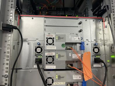
Review the components to be installed into each module in the stack below.
Note: The library configuration below is an example. The library EM and drive configuration is different for each hyperscaler customer.
|
|
|
Insert the magazines to their previous location in the module.
-
Insert Drive Bay Storage (DBS) magazine into the rear of the module.
-
Tighten the thumbscrew on the rear of the magazine.
-
Slide the drive gently into the drive bay until the lock lever is in the down position.
-
Tighten drive thumbscrew.
- Slide the power supply into its slot until the front bezel is sitting flush against the back of the module.
- Tighten the thumbscrew until finger tight.
If the module you are installing has drives and power supplies, do the following:
- Reconnect the power cables from power supplies.
- Reconnect the SAS or Fibre channel cables from the drives.
-
Place the Service Tray flat on the floor in front of the Control Service Module. When handling the Service Tray, use the blue handles and keep the tray level to avoid any damage to the tray.
-
Remove the orange Robot Shipping Restraint from the robot picker.
-
Place the Robot Shipping Restraint into storage at the front of the Service Tray.
-
Position the robot picker toward the rear of the Service Tray. When positioning the robot picker, do not touch the toothed belt that drives the robot picker mechanism. The belt is under low spring tension and is not designed to withstand direct intentional or unintentional handling. In addition, do not touch robot ribbon cable . The cable tether and orange cable guide are not designed to withstand direct intentional or unintentional handling. If the cable tether gets folded, creased, or bent in manner that is not part of normal robotic operation, the cable can take a permanent set that can later interfere with automatic robot operation.
Item Name 1 Robot Picker Belt 2 Robot Ribbon Cable 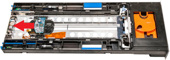
- Lift the new Service Tray up to the CSM. When handling the Service Tray, use the blue handles and keep the tray level to avoid any damage to the tray.
- Slide the new Service Tray into the CSM.
-
Gently push on the Service Tray while rotating the Service Tray Release Latch 90 degrees clockwise to the Lock position. You will hear a click when the Service Tray is locked into position.
Item Name Description 1 Service Tray Release Latch Rotate 90 degrees clockwise to the Locked postiion. -
Fold the Service Tray Release Latch down in the Locked position.