minute read
Unpack and Install
This guide provides hardware installation and initial system configuration instructions for the Quantum library.
Before You Begin
Review the following information before you begin an installation:
- Installation requires a minimum of two people.
- The shipping crate contains sharp and rough edges. Quantum recommends wearing gloves during the installation.
- Installation requires a 13 mm (1/2 inch) socket wrench and a diagonal cutter.
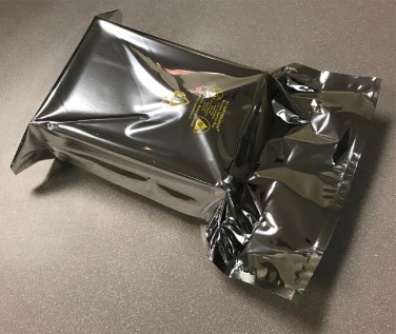
- Place all removed hardware into the accompanying bag. Place this bag inside the crate cubby hole.
- When installation is complete, return the crate to Quantum.
Unpack the Library
-
Place the shipping crate so that the front ramp and rear access panel are accessible. You must also have sufficient room to roll out the Scalar library rack from the shipping crate.
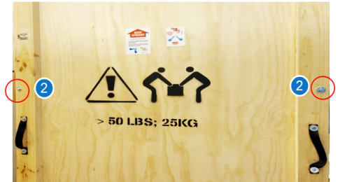
Figure 1: Shipping Crate - Front View
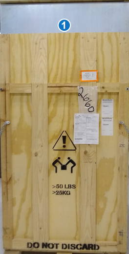
Item Description 1 Front Ramp Figure 2: Shipping Crate - Rear View
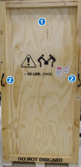
Item Description 1 Rear Access Panel 2 Hand Straps -
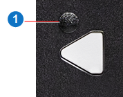
Using a diagonal cutter, remove the security seals. The security seals are wired and attached to one latch in each corner of the crate (4 total).
Figure 3: Security Seal
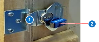
Item Description 1 Crate Latch 2 Security Seal -
Using a 13 mm (1/2 inch) socket wrench, remove the two front door and two rear door bolts.
Figure 4: Front Door Bolts
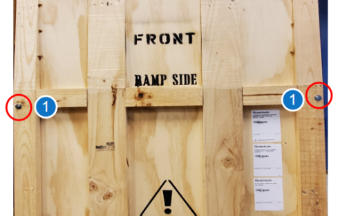
Figure 5: Rear Door Bolts
Item Description 1 Front Door Bolts 2 Rear Door Bolts
-
Slowly lower the ramp. There are two safety chains inside the ramp. Unhook the safety chains to continue lowering the ramp.
Caution: The front ramp is hinged, but it is heavy. Lifting straps are located on the inside of the front door to assist with lowering the door.
Figure 6: Safety Chains
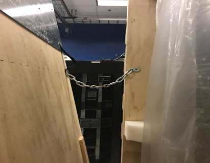
Figure 7: Front Crate - Ramp Down
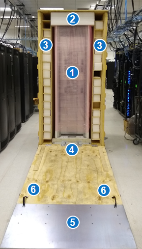
Item Description 1 Scalar Library 2 Foam Packaging 3 Scalar Magazines 4 Front Shipping Bracket 5 Front Ramp 6 Lifting Straps -
Unlatch the six rear latches and remove the rear access panel using the two hand straps provided on the panel.
WARNING: The access panel is not hinged and requires two people to safely remove.
Note: Your library configuration may be different from the image below.
Figure 8: Rear Crate - Access Panel Removed
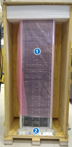
Item Description 1 Scalar i6 Library 2 Rear Shipping Bracket -
Once the front ramp has been lowered and the rear access panel removed, inspect the library rack for any apparent damage.
Check the shock and tilt indicator, located on the outside of the crate. If the shock or tilt indicator were triggered during shipping, please contact Quantum.
Figure 9: Shock Indicator

Figure 10: Tilt Indicator

-
Using a 13 mm (1/2 inch) socket wrench, remove the two bolts that secure the rear of the library to the shipping bracket.
Figure 11: Rear Shipping Bracket
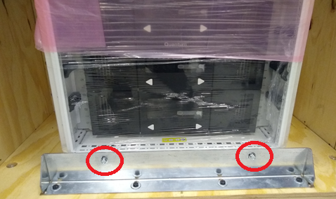
- Place the two bolts in the bag placed in the lower front right of the crate. The bolts will be returned with the crate.
-
Using a 13 mm ( 1/2 inch) socket wrench, remove the two bolts that secure the front of the library rack to the shipping bracket. Then remove the four bolts that attach the front shipping bracket to the crate.
Figure 12: Front Shipping Bracket
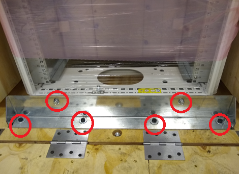
- Place the six bolts in the bag placed in the lower front right of the crate. The bolts will be returned with the crate.
- Place the front shipping bracket in the lower front right of the crate. The bracket will be returned with the crate.
-
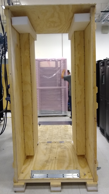
With one person pushing from the back, and one person guiding from the front, carefully roll the library out of the crate.
-
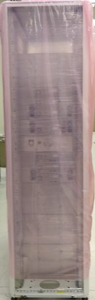
Remove the plastic sleeve from the library.
-
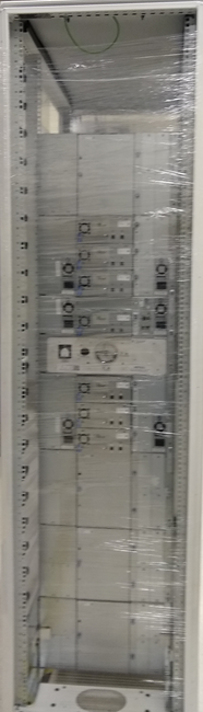
Remove the shrink wrap from the library. Inspect the library for any damage.
Note: Your library configuration may be different from the image below.
-
Move the library rack to its final location.
-
Remove the magazines from the cubicles in the crate. Set them aside until they are installed into the library.
Install Drives
If your system was shipped with the drives removed, you will need to install and cable the drives in the library.
The Scalar i6H library supports the following drives:
-
Up to 22 LTO-7 and above FC drives and LTO-9 SAS drives.
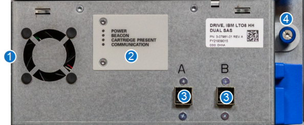
LTO-8 SAS Drive
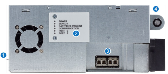
LTO-8 FC Drive
LTO-9 FC Drive
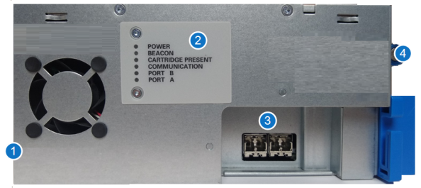
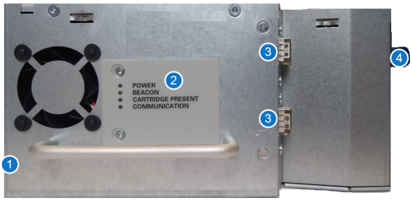
LTO-9 SAS Drive
| Item | Name | Description |
|---|---|---|
|
1 |
Unlock Lever |
The unlock lever must be pushed to the unlocked (up) position before the drive sled can be removed from the library. |
| 2 | LEDs |
The drive LEDs provide you with visual information that lets you know the drive is working correctly. After the library is powered up and working, the following indications tell you the drive is operating normally:
|
| 3 | Ports | The ports connect your drives to a server or a switch. You connect SAS drives with SAS Mini HD Cables. |
| 4 | Thumbscrew | Thumbscrews secure the drive sled to the chassis. |
Important Information - Drive Acclimation
Before opening the sealed ESD bag, the drive should be acclimated to the climate inside the facility or room location where the drive will be installed. Changes in temperature and humidity can cause condensation. It is recommended to leave drives in the packaging for a minimum of 24 hours before opening the sealed bag.
Place the sealed bag away from direct sources of air convection to minimize condensation.
If any external or internal condensation is seen on the sealed bag after 24 hours, remove the drive from the bag and acclimate the drive in the planned location for an extra 12 to 24 hours, or until no visible condensation remains.
Figure 13: Drive in Sealed Bag
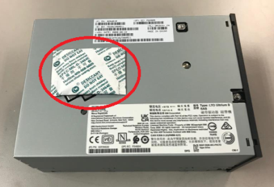
Once the bag has been opened, the drive should never be moved to a new location where temperature differences are greater than 5 degrees Celsius. If this type of drive relocation needs to occur, the drive should be placed in a sealed bag with desiccant and allowed to acclimate to the new location for a minimum of four hours.
Figure 14: Drive with Dessicant
Drive temperature and humidity specifications are as follows:
Note: The temperature and humidity specifications below are for LTO drives. For LTO media temperature and humidity specifications, refer to the Environmental Specifications in the Site Planning Guide.
| Mode | Air Inlet Temperature | Relative Humidity (Non-Condensing) | Altitude (Max) |
|---|---|---|---|
| Operating Mode |
10°C to 40°C (50°F to 104°F) |
20% to 80% 26°C (79°F) Wet Bulb Max |
3048 m |
| Recommended Operating Mode |
20°C to 25°C (68°F to 77°F) |
40% to 50% | 3048 m |
| Storage |
-40°C to 60°C (-40°F to 140°F) |
10% to 90% Non-Condensing |
3048 m |
| Shipping |
-40°C to 60°C (-40°F to 140°F) |
10% to 90% Non-Condensing |
12192 m |
To install a drive:
-
Slide the drive gently into the drive bay until the lock lever is in the down position.
-
Tighten drive thumbscrew.
-
Attach the SAS or FC cables to the drive.
Install the Library
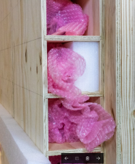
-
Remove the magazines from the bubble wrap. Place the bubble wrap back in the crate cubicles to return to Quantum.
Figure 15: Bubble Wrap in Cubicles
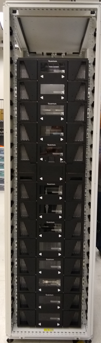
-
Load the magazines into the library rack.
Note: Magazines are side specific. Left magazines will not fit in right magazine slots. Right magazines will not fit in left magazine slots.
Note: Your library configuration and rack option may be different from the image below.
Figure 16: Library - Loaded Magazines
-
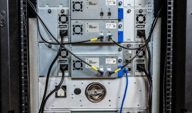
Inspect all data and power cords on the rear of the library. Ensure data and power cords are well seated.
Figure 17: Inspect All Cables and Power Cords
-
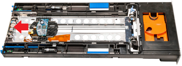
Remove the robot restraint from the Control Service Module Tray.
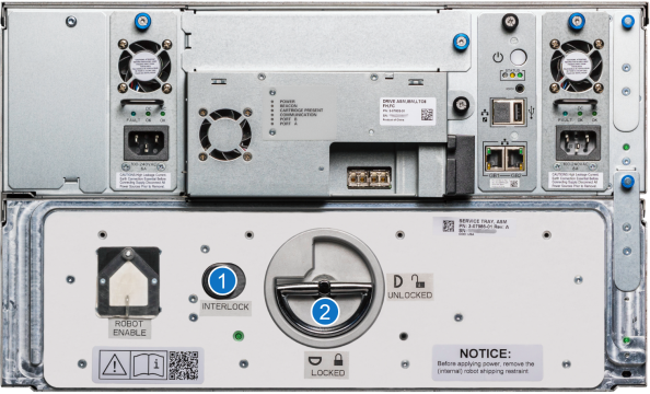
Item Description 1 Interlock Button 2 Service Tray Release Latch -
To unlock the Service Tray from the Control Service Module, push the Interlock button and rotate the Service Tray Release Latch 90 degrees counter clockwise.
- Pull on the Service Tray Release Latch to remove the Service Tray from the Control Service Module.
-
Remove the Robot Shipping Restraint.
Figure 18: Robot Shipping Restraint
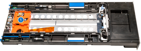
Item Description 1 Robot Shipping Restraint -
Place the Robot Shipping Restraint into the Service Tray storage compartment.
Figure 19: Service Tray - Store Robot Shipping Restraint
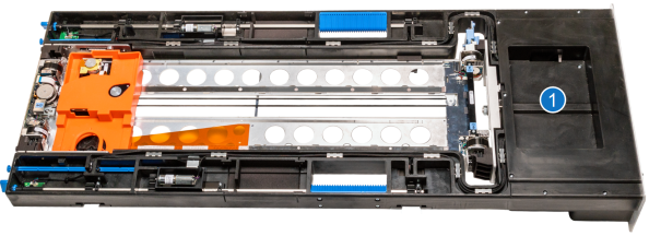
Item Description 1 Robot Shipping Restraint Storage -
Position the robot towards the rear of the Service Tray to avoid catching the ribbon cable when inserting the tray back into the Control Service Module.
Figure 20: Position Robot to Rear
Slide the Service Tray back into the Control Service Module.
-
Rotate the Service Tray Release Latch 90 degrees clockwise. You will hear a click when the Service Tray is locked into position.
- Fold the Service Tray Release Latch down.
-
- Connect the library rack to your network.
- Connect the power cables to a power supply. The library will power on and begin to initialize.
-
Once the library has initialized, go to the Network menu option in the Local User Interface (LUI) on the front of the library to access the system IP Address.
Figure 21: Local User Interface (LUI)
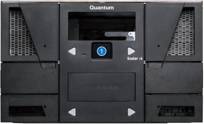
Item Description 1 Local User Interface (LUI) -
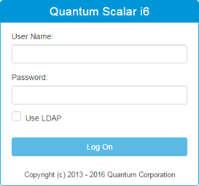
Type the IP Address into a web browser to log on to the library. Scalar i6 does not support the Internet Explorer browser.
The default log on is:
User Name admin Password password Figure 22: Scalar Library Log On
Install Magazine Eject Stops
If the Scalar i6H library was ordered with Magazine Eject Stops, install them now.
| Name | Quantity | Included with... |
|---|---|---|
| Left Magazine Eject Stop | 1 | Magazine Eject Stop Kit |
| Right Magazine Eject Stop | 1 | Magazine Eject Stop Kit |
| M3 x 1 T10 Torx Button Head Screws | 2 | Magazine Eject Stop Kit |
Important Information
Install the magazine stops one at a time. This will ensure the electronics behind the bezel stay in place.
-
Remove the plug above the magazine eject button.
Item Description 1 Airgap Magazine Eject Stop Hole - Remove the screw from the magazine eject stop hole.
-
Install the magazine eject stop into the hole. The arrow should be pointing towards the center of the module.
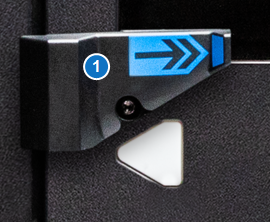
Item Description 1 Airgap Magazine Eject Stop -
Insert the M3 x 1 screws provided with the magazine eject stops into the magazine eject stop hole and tighten.
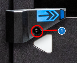
Item Description 1 M3 x 1 Torx Screw -
Repeat steps 1-3 for each magazine eject stop.
Return the Crate to Quantum
Once installation is complete, you will need to return the crate to Quantum. Do the following:
-
Place all the following packing material into the crate.
-
Close up the crate:
- Raise and latch the front ramp.
- Reinstall and latch the rear access panel.
- Using a 13 mm (1/2 inch) socket wrench, re-install the two front door and two rear door bolts.
-
Follow the attached instructions for arranging return shipment to Quantum.
Quantum Contact Information
When the crate is ready to return to Quantum, please contact the Quantum Logistics team with following information:
- Pick up company name and address
- Contact name and phone number
- Quantum sales order number
- Office hours of pick up location
Quantum Logistics Team