minute read
Remove and Replace the Robot Service Tray
The Scalar Control Service Module (CSM)
Overview
The Scalar Control Service Module (CSM) simplifies the replacement of a robot without the use of tools or the need to remove Expansion Modules (EMs) to gain access to the robot.
Important Information - Library Firmware
-
Robot Service Trays that contain an updated robot (9-06181-02) require the library to run on firmware version 290 or above. To avoid the library going into a Not Ready state and generating a RAS ticket (ET026), upgrade the firmware to 290 or above before starting the service tray replacement (see Update Library Firmware).
-
Robot Service Trays that contain the previous version of the robot (9-06181-01) do not require a library firmware update.
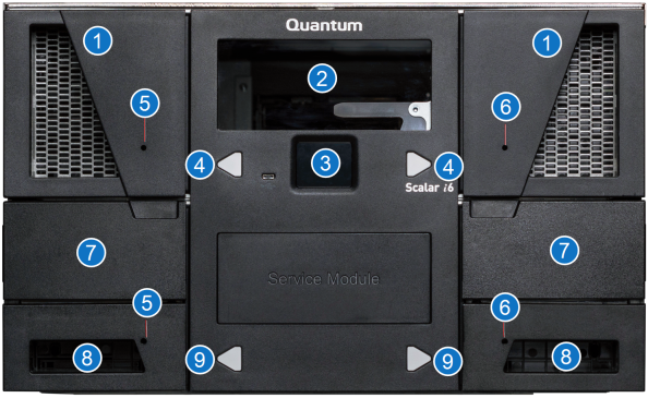
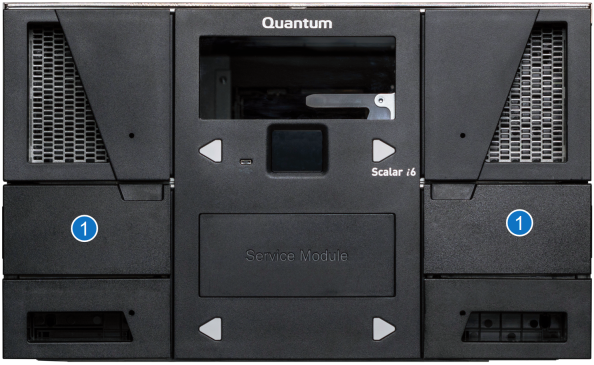
Control Service Module (CSM) Front View
| Item | Name | Description |
|---|---|---|
|
1 |
Magazines |
25 slot magazines (i6) 30 slot magazines (i6H). |
| 2 | CSM Window | Allows you to view the internal components. |
| 3 | Local User Interface (LUI) | Allows you to perform some library functions when you can’t access the WebGUI. |
| 4 | Magazine Release Request Buttons | Releases the corresponding magazines for removal. |
| 5 | Left Magazine Manual Release | Allows you to release the left magazine when the library is not powered on. |
| 6 | Right Magazine Manual Release | Allows you to release the right magazine when the library is not powered on. |
| 7 | Service Tray Access Doors | Access to the override button and paddle that controls the buttons and paddles of the Service Tray receive and capture features. |
| 8 | Magazines |
10 slot magazines (i6) 12 slot magazines (i6H). |
| 9 | Magazine Release Request Buttons | Releases the corresponding magazines for removal. The buttons can also be used to request robot replacement. |
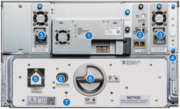
Control Service Module (CSM) Rear View
| Item | Name | Description |
|---|---|---|
|
1 |
Drive | Dual port SAS drive. |
| 2 | System Control Board (SCB) | Controls library functions. Network ports are labeled GB1 and GB2. |
| 3 | Power Supply | Provides power to the library. |
| 4 | Module Interconnect | Provides connectivity from the module to the module above. |
| 5 | Robot Enable Button | Moves the robot into the Service Tray in preparation for removal. Can also enable the robot. |
| 6 | Interlock Button | Locks the Service Tray Release Latch. |
| 7 | Power LED | Indicates power to the Service Tray, Robot, and Cable Spool. |
| 8 | Service Tray Release Latch | Locks and unlocks the Service Tray into the Control Service Module. Is also used to pull and push the Service Tray into the Control Service Module. |
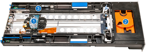
Control Service Module (CSM) - Service Tray
| Item | Name | Description |
|---|---|---|
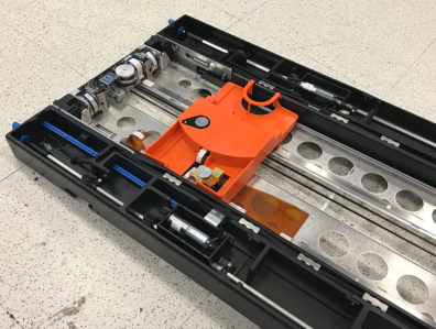
| 1 | Robot Picker | The mobile part of the robot that moves media between slots and drives. The Robot Shipping Restraint locks over the picker to prevent the robot from moving during shipping. |
|
2 |
Robot Shipping Restraint Storage | Used to store the Robot Shipping Restraint in the Service Tray. |
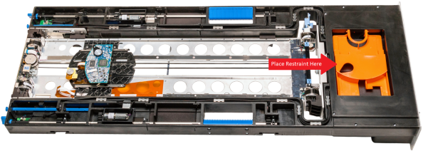
| 3 | Robot Shipping Restraint Pocket | This is the location aligned over the reach assembly where the Robot Shipping Restraint is placed on the Robot Picker. |
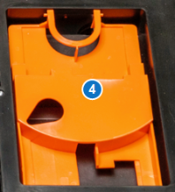
| 4 | Robot Shipping Restraint | Prevents the robot from moving during shipping. Placed over the Robot Picker. |
Handling the Service Tray
To properly handle the Service Tray, Quantum recommends the following:
-
Place the Robot Shipping Restraint on the Robot Picker when handling the Service Tray. This will prevent excessive movement and damage to the Robot Picker.
Note: When restrained, the robot picker must aligned over the reach assembly in the location below.
-
Use the blue handles on the Service Tray when handling the Service Tray.
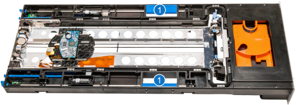
Item Name Description 1 Service Tray Handles Use handles when lifting and moving Service Tray. -
Keep the Service Tray horizontally flat. Handling the Service Tray vertically or at an angle may cause damage to tray components.
Important Information
-
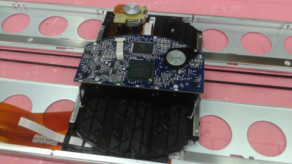
When the Service Tray is out of the library, do not touch the toothed belt that drives the robot picker mechanism. The belt is under low spring tension and is not designed to withstand direct intentional or unintentional handling.
-
When the Service Tray is out of the library, do not touch robot ribbon cable . The cable tether and orange cable guide are not designed to withstand direct intentional or unintentional handling. If the cable tether gets folded, creased, or bent in manner that is not part of normal robotic operation, the cable can take a permanent set that can later interfere with automatic robot operation.
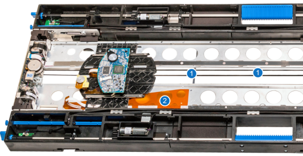
| Item | Name |
|---|---|
| 1 | Robot Picker Belt |
| 2 | Robot Ribbon Cable |
Remove the Service Tray
To remove the robot, you must remove the Service Tray from the Control Service Module (CSM).
-
There are four different options to initiate removal of the robot from the Scalar library:
 Robot Enable Button
On the rear of CSM, push the Robot Enable button for approximately 2 seconds. The button will slowly blink amber. This indicates that the robot is moving into removal position. Once the robot removal positioning is complete, the button will be solid amber.
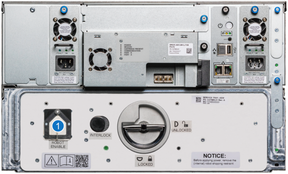
Item Name Description 1 Robot Enable Button Moves the robot into the Service Tray in preparation for removal. Can also enable the robot. WebGUI
To position the robot for removal using the WebGUI, do the following:
- Select Devices.
- From the North Panel, click the + next to Robotics. Select the checkbox for the Robot.
-
In the Operations Panel, click Position. The Position window displays.
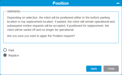
- Select the Replace radio button.
- Click Apply. This positions the robot into the CSM.
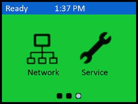
LUI
To position the robot for removal using the LUI, select Service > Maintenance > Robot Position > Replace.
Note: The robot may take up to 5 minutes to park into the Service Tray.
Troubleshooting - Robot Positioning
If the Robotics Enable button and Front Magazine Release Request buttons rapidly blink amber and then turn off during the robot positioning for removal, an error has occurred and a RAS ticket will be generated. Review the RAS ticket in the WebGUI (RAS Tickets) or LUI (Ticket > View RAS Tickets) for further troubleshooting instructions.
-
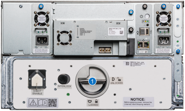
To unlock the Service Tray from the CSM, press the Interlock button. With the Interlock button pushed, lift the Service Tray Release Latch up and rotate it 90 degrees counterclockwise to the Unlocked position.
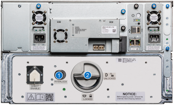
Item Name Description 1 Interlock Button Push the Interlock button while rotating the Service Tray Release Latch. 2 Service Tray Release Latch Rotate 90 degrees counterclockwise to the Unlocked postiion. -
Pull on the Service Tray Release Latch to remove the Service Tray from the CSM.
-
Place the Service Tray flat on the floor in front of the Control Service Module. When handling the Service Tray, use the blue handles and keep the tray level to avoid any damage to the tray.
-
Remove the Robot Shipping Restraint from storage and place on the robot picker.
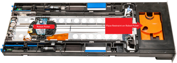
Note: When restrained, the robot picker must be in the location noted below.
-
Once the restraint is on the robot picker, you may now move the Service Tray. When moving the Service Tray, use the blue handles and keep the tray level.
Install the New Service Tray
-
Place the Service Tray flat on the floor in front of the Control Service Module. When handling the Service Tray, use the blue handles and keep the tray level to avoid any damage to the tray.
-
Remove the orange Robot Shipping Restraint from the robot picker.
-
Place the Robot Shipping Restraint into storage at the front of the Service Tray.
-
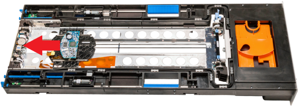
Position the robot picker toward the rear of the Service Tray to avoid catching the ribbon cable.
- Lift the new Service Tray up to the CSM. When handling the Service Tray, use the blue handles and keep the tray level to avoid any damage to the tray.
- Slide the new Service Tray into the CSM.
-
Gently push on the Service Tray while rotating the Service Tray Release Latch 90 degrees clockwise to the Lock position. You will hear a click when the Service Tray is locked into position.
Item Name Description 1 Service Tray Release Latch Rotate 90 degrees clockwise to the Locked postiion. -
Fold the Service Tray Release Latch down in the Locked position.
-
Push the Robot Enable button to vary the robot back on. The button will slowly flash green while the robot is varying back on, and turn solid green when the vary on procedure is complete.
Note: If you do not push the Roboti Enable button, the robot automatically varies back on after 15 minutes.
Item Name Description 1 Robot Enable Button Moves the robot into the Service Tray in preparation for removal. Can also enable the robot. Troubleshooting - Robot Enable
If the Robotics Enable button and Front Magazine Release Request buttons rapidly flash amber and then turn off, an error has occurred and a RAS ticket will then be generated. Review the RAS ticket in the WebGUI (RAS Tickets) or LUI (Ticket > View RAS Tickets) for further troubleshooting instructions.
-
The Power LED light will appear once the robot successfully varies back on. This light indicates that there is power to the Service Tray, robot, and cable spool.
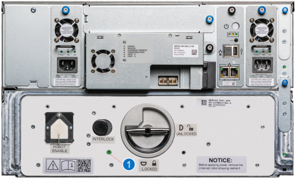
Item Name Description 1 Power LED Indicates power to the Service Tray, Robot, and Cable Spool.
Troubleshooting
The Service Tray can be manually removed from the CSM if the following issues occur:
- The robot removal request fails and the robot varies off.
- The library does not have power.
Use the following procedure to remove the service tray.
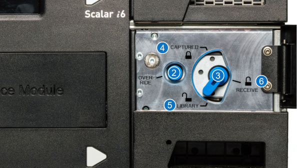
The robot can be manually positioned into the Service Tray by using the left and right Service Override buttons and paddles. These buttons and paddles can be accessed through Service Tray Access Doors on the front of the CSM.
| Item | Name | Description |
|---|---|---|
| 1 | Service Tray Access Doors | Access to the override button and paddle that controls the buttons and paddles of the Service Tray receive and capture features. |
| 2 | Service Override Button |
This button must be engaged to turn the paddle. |
| 3 | Paddle |
Turn the paddle to engage one of three paddle positions - captured, receive, and library. Caution: If the paddle does turn freely by hand is should not be forced. This typically implies the robot is not in a proper position. Forcing the paddle can cause damage to the Service Tray. |
| 4 | Paddle - Captured Position | Paddle position used to manually secure the robot into the Service Tray. The Receive Shelves and Capture Shelves are both extended. |
|
5 |
Paddle - Library Position | Paddle position when robot is in service. The Capture Shelves and Receive Shelves are retracted into the Service Tray. |
| 6 | Paddle - Receive Position | Paddle position used to manually receive robot into Service Tray. The Receive Shelves are extended and Capture Shelves are retracted. |

Note: The following procedure should be followed from the front of the library.
-
Using the library windows in the stack, visually identify the location of the robot within the library.
-
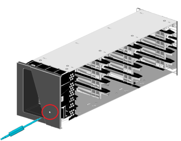
In order to access the robot, remove alternating library magazines from the location of the robot to the CSM. It is important that you properly mark the location of each removed magazine.
Review - How to Remove Magazines
Caution: Insert a T8 torque screwdriver into the magazine release hole until the magazine pops out. Remove the magazine.
-
Before you move the robot, verify that the robot picker is retracted.
Extended Robot Picker
Retracted Robot Picker
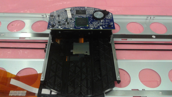
- Manually push the robot down (if it is above the CSM) or up (if it is above the CSM) until it is visible though the CSM window. To safely push the robot to the CSM, rotate pushing on the front and rear of the robot.
-
On the front of the CSM, open the left and right Service Tray Access Doors.
Item Name Description 1
Service Tray Access Doors Access to the override button and paddle that controls the buttons and paddles of the Service Tray receive and capture features. -
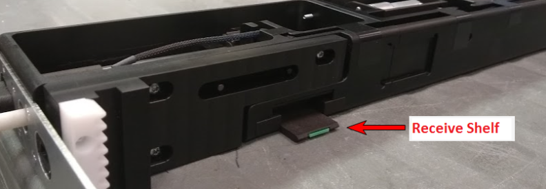
Press the Service Override button while rotating the Paddle to the Receive position. The Receive Shelf will appear within the Service Tray. Repeat this step in the other Service Tray Access panel.
Caution: If the paddle does turn freely by hand is should not be forced. This typically implies the robot is not in a proper position. Forcing the paddle can cause damage to the Service Tray.
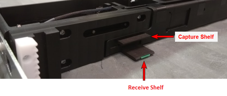
- Gently push the robot down onto the Receive Shelves.
-
Once the robot is seated on the Receive Shelves, depress the Service Override button while rotating the paddle to the Captured position. Repeat this step in the other Service Tray Access panel.
Caution: If the paddle does turn freely by hand is should not be forced. This typically implies the robot is not in a proper position. Forcing the paddle can cause damage to the Service Tray.
Note: If the paddle does not rotate to the Captured position, the robot is not fully seated on the Catch Shelves.
-
Once the robot is successfully captured, you can remove the Service Tray. To unlock the Service Tray from the CSM, press the Interlock button. With the Interlock button pushed, lift the Service Tray Release Latch up and rotate it 90 degrees counterclockwise.
Item Name Description 1 Interlock Button Push the Interlock button while rotating the Service Tray Release Latch. 2 Service Tray Release Latch Rotate 90 degrees counterclockwise to the Unlocked postiion. -
Pull on the Service Tray Release Latch to remove the Service Tray from the CSM. When handling the Service Tray, use the blue handles and keep the tray level to avoid any damage to the tray.