minute read
Scalar i6000 Devices
Overview
Devices are the physical components of the library that can be accessed, removed or have their status changed.
The available devices are as follows:
| Robotics |
Includes the robot and allows you to position the robot for maintenance |
| Import/Export |
|
| Ethernet Blade |
Displays all Ethernet Expansion Blades (EEBs) and Ethernet Management Blades (EMBs) contained in your library available for configuration. |
| Towers |
Displays all HDEM towers in your library. |
Layout
Lists all available library devices.
Lists all configured parameters for any highlighted partition.
Provides options for device interaction.
| Actions | |
|---|---|
| Vary-On |
Allows you to vary-on the robot to prepare it for positioning |
| Vary-Off |
Allows you to vary-off the robot for maintenance procedures |
| Enable Robotics |
Allows you to enable your robot(s) |
| Restart |
Allows you to restart a blade to activate any changes |
| Power-Cycle |
Allows you to power off and power on a selected device |
| Online |
Allows you to a selected device to put online |
| Offline |
Allows you to a selected device to put offline |
| Lock |
Allows you to lock your I/E station |
| Unlock |
Allows you to unlock your I/E station |
| Identify On |
Allows you to activate the identify LED pattern |
| Identify Off |
Allows you to deactivate the identify LED pattern |
| Port Reset |
Allows you to reset the ports on your fibre channel blade. |
Tasks
Configuration
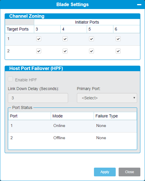
The Blade Setting feature is only used if you have fibre channel blades installed in your library. You use this feature to:
- channel zone what ports on the blade you want to use to communicate with attached drives
- configure Host Port Failover (HPF), where you assign which port on the blade will be the primary port to communicate with attached drives
- From the Navigation panel, select Devices.
- In the North Panel, select the check box next to a Fibre Channel blade (FCB).
-
In the Operations panel, click Blade Settings.

Item Description Action Channel Zoning Channel zoning enables you to control access between specific target Fibre Channel (FC) ports and initiator channels on an I/O blade in your library. If you make changes to the channel zoning settings, you must reboot the I/O blade for the new settings to take effect.
Caution: If you change channel zoning after host computers or applications have already discovered devices, you must make sure that device discovery occurs again. Device discovery could occur automatically when you reboot the library. Some host computers have plug and play capability, which can discover devices automatically. Host applications might discover devices automatically
Select the check box in the cell where the target port and the initiator channel meet if you want to permit access, . If you want to restrict access, clear the check box in the cell where the target port and the initiator channel meet.
Note: When you select a check box in the cell, the entire channel is zoned.
Initiator Ports Initiator ports are connected to your drives and allow the host to communicate with the drives. Ports 3 thru 6 are configured to be host initiators. Select the check box for each port you want the host to use to communicate with attached drives. All initiator ports are selected by default. Target Ports Target ports are connected to your host(s) and allow communication to drives attached to the FCB. Ports 1 and 2 are configured to be host targets. No action. Host Port Failover (HPF) HPF enables the library to continue operations in the event a port is uncommunicative without requiring you to reconfigure the host or the SAN.
Note: Both ports must be attached to the same SAN fabric to provide host access.
Enable HPF Allows you to use an alternate “standby” target port on an I/O blade to assume the identity and LUN mapping configuration of the primary “active” target port if the primary port fails.
Note: To enable HPF, you must make sure that two ports on the FC I/O blade are in target mode and point-to-point connection.
Select the check box to enable HPF. Deselect the check box to disable HPF. Link Down Delay (Seconds) Allows you to sets the timeout threshold, in seconds, before link down status applies. Enter the amount of seconds you want to set as the threshold. Primary Port Allows you to determine the port you want to use for host communications. The other target port is kept idle. This way you configure the recovery settings to determine how the failed port behaves after it is restored from a failed state. Select the target port you want to use as the primary port from the drop-down menu. Port Status Displays the status of the configured target ports. No action. -
Click Apply to save your settings.
-
Click Close to exit the window.
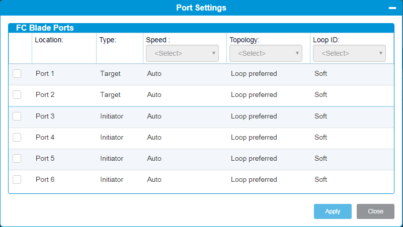
The Port Settings feature allows you to configure connectivity parameters for the ports on your fibre channel blade.
Note: To use Host Port Failover (HPF), you must have the target ports set to point-to-point. See Blade Settings for more information on HPF.
- From the Navigation panel, select Devices.
- In the North Panel, select the check box next to a Fibre Channel blade (FCB).
-
In the Operations panel, click Port Settings.
-
To change the current settings for any port associated with the selected blade, click the check box next to the port.
Item Description Action Location Lists the available ports, 1-6. No action. Type Lists the type of port, either Target or Initiator.
Note: Initiator ports require loop mode topology.
No action. Speed Lists the available speed for the selected port. Values include:
- Auto (default) - automatically sets the interface speed
- 1 Gb/s
- 2 Gb/s
- 4 Gb/s
- 8 Gb/s
Select a value from the drop-down menu. Topology Lists the available drive topology for the selected port. Values include:
- NA
- Loop Preferred (LN) (default) - Auto-configure trying L-Port first
- Point to Point (P2P) - Force N-Port
- Loop (L) - Force L-Port
- Point Preferred (NL) - Auto-configure trying N-Port first
Note: Initiator ports require loop mode topology.
Select a value from the drop-down menu. Loop ID Select from the following options for FC drives only:
- Soft ID (default) - indicating the loop id - if required for any NL, LN or L topology - is determined by the library
- Hard ID - enables Loop ID settings for individual drives to have the loop id displayed and allow for user selections from 1 to 125.
-
Note: If the topology is set to P2P, the Loop Id selection is disabled
Select a value from the drop-down menu.
Note: This is only available for Initiator ports.
-
Click Apply to save your settings.
-
Click Close to exit the window.
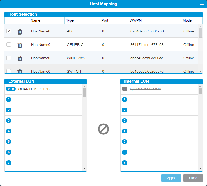
The Host Mapping feature allows you to give a selected host access to partitions and drives. The screen displays all partitions and drives connected to the blade to which the host is attached.
All drives connect to a FC I/O Blade can be selected for Host Mapping. If drives are not assigned a Path Failover/Native Storage Networking license, you will not be able to configure host mapping.
Note: Any drive connected to an I/O Blade should not be connected to an Ethernet Expansion Blade (EEB) at the same time.
- From the Navigation panel, select Devices.
- In the North Panel, select the check box next to a Fibre Channel blade (FCB).
-
In the Operations panel, click Host Mapping.

-
For an interactive demonstration of Host Mapping, click here.
Item Description Action Host Selection Lists all resources (partitions and drives) connected to the blade to which the host is attached.
Note: If you delete a partition that is currently displayed on the FC Host LUN Mapping dialog box, the internal LUN and any external LUN mappings for the partition will no longer appear on the dialog box.
You can also add a host that isn't currently attached by clicking the + and then manually entering values for the new host.
Select the check box next to the host you want to map. The host resources will appear below.
When the host is selected, you can also edit the host name, host type, and host port number.
Note: If the same host is visible on other I/O Blades, host edits must be done on each individual I/O Blade.
External LUN Displays resources (drives and partitions) connected to the I/O Blade that have been manually reassigned to a new map position.
Note: Quantum recommends mapping a partition to a host through only one I/O Blade. Mapping a partition to a host across multiple I/O Blades is not recommended.
Drag the device to an External LUN position.
To remove the device from the External LUN column, drag and drop the device back to it's position in the Internal LUN column.
You can also use the Arrow button to move devices.
Internal LUN Displays resources (drives and partitions) connected to the I/O Blade that have not yet been manually reassigned to a new map position. Drag the device to an Internal LUN position.
To remove the device from the Internal LUN column, drag and drop the device back to it's position in the External LUN column.
You can also use the Arrow button to move devices.
-
Click Apply to save your settings.
-
Click Close to exit the window.
Actions
There are two device states:
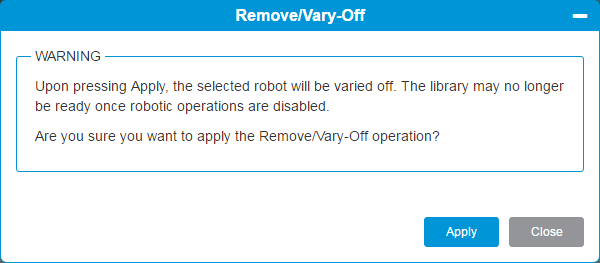
- Vary Off - powers off a device (robot or HDEM tower).
- Vary On - powers on a device (robot or HDEM tower).
You vary a device off to prepare for removal and maintenance.
Note: If the robot is varied off, it will be automatically varied back on after a restart of the library.
Important Information - HDEM Towers
Do not attempt to vary on a tower if robotics are disabled. Tower movement requires the robotics to be enabled.
- From the Navigation panel, select Devices.
- In the North Panel, select the check box next to the robot or tower.
-
In the Operations panel, click Vary On or Vary Off.

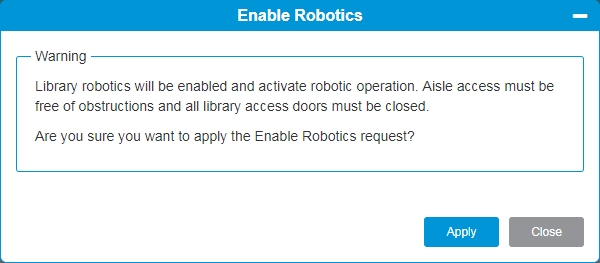
This feature allows you to remotely bring a robot back online and functioning. The robotics is disabled when aisle doors on the system are opened.
- From the Navigation panel, select Media.
- In the North Panel, select the check box next to a robot.
-
In the Operations panel, click Enable Robotics.
-
Click Apply to save your settings.
-
Click Close to exit the window.
Power cycling a device will power a device off, and then turn it on again. Power cycling can help a device resolve small internal errors and once again function properly.
- From the Navigation panel, select Devices.
- In the North Panel, select the check box next to a blade.
- In the Operations panel, click Power-Cycle.
-
Click Apply to save your settings.
-
Click Close to exit the window.
There are two tape drive modes:
- Online — Device is available for use. This is the normal operating mode for the tape drive.
- Offline — Device is offline to the host application and is not available for cartridge load and unload (move) operations initiated by the host application, but it remains available for WebGUI initiated commands.
Some operations require that a device be offline. You can take a device offline rather than the entire library or partition so as to minimizedisruption of library operations.
Note: Using the library to change tape drive mode may affect the host application. See your host application documentation for more information.
- From the Navigation panel, select Drives.
- In the North Panel, select the check box next to the drive(s) you want to change status.
- In the Operations panel, click Online or Offline.
The Lock and Unlock features are used for I/E stations. Your Scalar i6000 I/E stations have multiple open and close sensors. When you are finished accessing the I/E station, make sure the station door is fully closed.
There are two reasons the I/E station door locks:
- The library imports or exports a cartridge from the I/E station door. While the library is attempting to import or export a tape from a given I/E station slot, only the associated I/E station door is locked in the closed position. All other I/E station doors remain accessible. On a Get command from an I/E station slot, the associated I/E station door remains locked until the media has been successfully moved to its destination. This allows the media to be returned to the I/E station slot in the event of a Put error.
- A user has requested that the I/E station door be locked.
- The application software has locked the I/E station as part of the normal tape movement process.
To manually lock or unlock an specific I/E station door:
- From Navigation panel, select Devices.
- In the North Panel, select the check box next to the I/E station you want to lock or unlock.
- In the Operations panel, click Lock or Unlock.
There are instances when a specific blade needs to be identified in the physical library. In these cases, using the Identify feature causes the LEDs on the back of the blade to blink rapidly so that the blade can be found quickly. After a designated amount of time, the LEDs go back to normal operation.
When you click Identify On, a message appears that informs you that you can now identify the blade by the rapidly blinking LED on the back of it. After you find the blade, click Identify Off to stop the rapid blinking.
- From the Navigation panel, select Devices.
- In the North Panel, select the check box next to the device you want to identify.
- In the Operations panel, click Identify On or Identify Off.
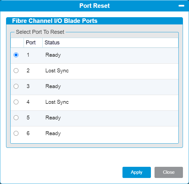
This feature allows you to reset ports on a Fibre Channel I/O Blade.
- From the Navigation panel, select Devices.
- In the North Panel, select the check box next to the blade you want to reset the ports.
-
In the Operations panel, click Port Reset.

- Select the radio button next to the FC blade port you wish to reset.
- Click the Apply button. The port will reset.