Interpreting LEDs
Interpreting Blade Status LEDs
Each of the following library blades has a set of green, amber, and blue LEDs that indicate blade processor status, health status, and power control status:
- Management Control Blade (MCB)
- Control Management Blade (CMB)
- Ethernet Management Blade (EMB)
- Fibre Channel (FC) I/O Blade
- Ethernet Expansion Blade
- Robotics Control Unit (RCU)
- Library Motor Drive (LMD)
- Library Power Control (LPC)
Click the image below to show the locations and colors of the status LEDs on the five blades that can be in the library.
Blade status LEDs provide troubleshooting information that you can use in conjunction with tickets that the library creates. However, the LEDs might not directly correspond to tickets. The LEDs can indicate a firmware or hardware problem so severe that the library cannot create or display a ticket. For example, if the MCB firmware becomes inoperable, the amber LED flashes at 1 Hz, but the library might not be able to display any related tickets.
| LED Color | Represents | Possible States and Explanations |
|---|---|---|
| Green | Processor status |
|
| Amber | Health status |
Auto-leveling takes about three minutes for each blade, and blades within an I/O management unit auto-level in series. It can take as long as three minutes for the power and control subsystem to download. Never remove a blade when the amber LED is solid on unless it has been on continuously for at least 10 minutes. |
| Blue | Power control Status |
|
| LED Color | State and Explanations |
|---|---|
| Green |
Blinks one time every second (1 Hz) — blade’s main processor is operating normally (however, this does not apply to the LMD; solid on indicates that the LMD’s main process is operating normally) Note: If there are issues during an update using an embedded flash, the green LED is solid for two seconds, and then off for one second. |
|
Amber |
Solid off — no errors are detected; blade’s power and control subsystem is operating normally |
| Blue | Blinks one time every 10 seconds (flash) — blade is powered on; operating normally |
Actions Based on LED States
When the RAS system is operating properly, service actions should be based on tickets first and foremost. However, some situations occur when the amber LED indicates problems that are not detected by the ticket system. You should always act on any amber LED that is solidly on, which indicates that the blade’s power and control subsystem has failed. In this case, replace the blade.
When you replace a blade FRU or escalate a problem based on LED states, perform the following steps:
- Observe and report the timing pattern of the blue, amber, and green LED group. Spend at least 30 seconds observing the LEDs and record the results in the service request (SR) and on any equipment failure report form that you return with the part. Proper reporting of all LED states is critical for determining the root cause of the failure.
- Capture a system snapshot and send it to technical support for analysis.
Interpreting Drive Status LEDs
The library reports all drive issues that can affect customer operations. In addition to examining library reports, you should observe drive sled link LED and status LED activity.
| LED Color | Represents | Possible States and Explanations |
|---|---|---|
| Green | Processor status |
|
| Amber | Health status |
|
| Blue | Power control Status |
|
| LED Color | State and Explanations |
|---|---|
| Green |
Blinks one time every second (1 Hz) — drive sled’s main processor is operating normally. The green LEDs for all drive sleds that are operating normally blink together. |
|
Amber |
Solid off — no errors are detected; drive sled’s controller is operating normally |
| Blue | Blinks one time every 10 seconds (flash) — drive sled is powered on; operating normally |
Interpreting Fibre Port Link LEDs
A fibre port link LED shows the state of the Fibre Channel link and whether the link is ready to transmit commands.
Drive Sled Fibre Channel Link LED
The Fibre Channel link LED for a drive sled is located on the rear of the drive sled.
| LED Color | Represents | Possible States and Explanations |
|---|---|---|
| Green | LIP and activity |
|
| Amber | Online and light detected |
|
| No color |
|
| LED Color | Represents | Possible States and Explanations |
|---|---|---|
| Green | LIP and activity |
|
| Amber | Online and light detected |
|
| No color |
|
Note: A UDS-2 drive with no fiber optic cable plugged in is healthy if the link LED is solid off. A UDS-3 drive with no fiber optic cable plugged in is healthy if the LED is amber and blinking at regular intervals, indicating that the library has enabled the drive data bus, but no light is detected.
FC I/O Blade Fibre Port Link LED
The link LED for an FC I/O blade fibre port is located next to the port. On the I/O blade faceplate, black lines indicate how each link LED belongs to a port. Click the image below to view LED locations.
| FC I/O Blade Model | Possible Green LED States and Explanations |
|---|---|
| 7404 4 gigabit/sec |
|
Interpreting Ethernet Expansion Blade LEDs
The status LEDs for an Ethernet Expansion blade are located at the top of the EEB above ETH 6. Click the image below to view LED locations.
| Blue | Green | Amber | Description |
|---|---|---|---|
| Off | Off | Off | No power |
| 1 Hz | Off | Off | Powered down - ready for removal |
| Off | Off | On | Booting |
| Flash | 1 Hz | Off | Normal |
| Flash | 10 Hz | Off | Normal - Identify |
| LED Color | Possible States and Explanations |
|---|---|
| Green |
|
| Amber |
|
Interpreting MCB Port LEDs
The MCB has LEDs for the Ethernet, Fibre Channel, and SCSI ports.
MCB Ethernet Port LEDs
The LEDs on the MCB Ethernet port indicate status and activity. Click the image below to view LED locations.
| LED Color | Possible States and Explanations |
|---|---|
| Green |
|
| Amber |
|
MCB Fibre Channel and SCSI Port LEDs
The LEDs for the MCB Fibre Channel and SCSI ports are for future use. Ignore LED behaviors that might appear. Click the image below to view LED locations.
Interpreting LBX Terminator LEDs
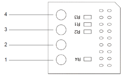
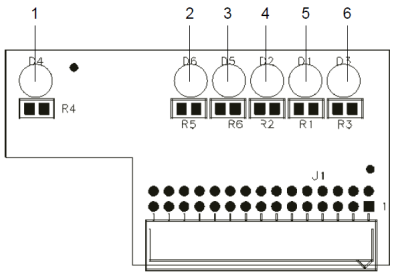
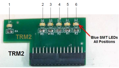
The LBX terminator has three versions. Version 01 has four LEDs and Versions 03 and 2.0 have six LEDs.
LBX Terminator Version 01 LEDs
The LBX terminator has four green LEDs that indicate the presence of modules in the library. The terminator must be located in the LBX of the last expansion module. The LED status should reflect the physical installed module count of the system.

| LED On/Off Combinations | Explanation | |||
|---|---|---|---|---|
| 1 | 2 | 3 | 4 | |
| Off | Off | Off | Off | Robotics are disabled, the access door is open, or the LBX terminator is misaligned. |
| On | Off | Off | Off | The library has one control module and no expansion modules. |
| On | On | Off | Off | The library has one control module and one expansion modules. |
| On | On | On | Off | The library has one control module and two expansion modules. |
| On | On | On | On | The library has one control module and three expansion modules. |
| On | Off | On | On | The library has one control module and four expansion modules. |
| On | On | Off | On | The library has one control module and five expansion modules. |
| On | On | On | Off | The library has one control module and six expansion modules. |
| On | Off | Off | On | The library has one control module and seven expansion modules. |
LBX Terminator Version 03 LEDs
The LBX terminator has six green LEDs that indicate the presence of modules in the library.

| LED On/Off Combinations | Explanation | |||||
|---|---|---|---|---|---|---|
| 1 | 2 | 3 | 4 | 5 | 6 | |
| Off | Off | Off | Off | Off | Off | Robotics are disabled, the access door is open, or the LBX terminator is misaligned. |
| On | Off | Off | Off | Off | Off | The library has one control module and no expansion modules. |
| On | Off | Off | On | Off | Off | The library has one control module and one expansion modules. |
| On | Off | Off | On | On | Off | The library has one control module and two expansion modules. |
| On | Off | Off | On | On | On | The library has one control module and three expansion modules. |
| On | Off | Off | Off | On | On | The library has one control module and four expansion modules. |
| On | Off | Off | On | Off | On | The library has one control module and five expansion modules. |
| On | Off | Off | Off | On | Off | The library has one control module and six expansion modules. |
| On | Off | Off | Off | Off | On | The library has one control module and seven expansion modules. |
| On | On | Off | Off | Off | Off | The library has one control module and eight expansion modules. |
| On | On | Off | On | Off | Off | The library has one control module and nine expansion modules. |
| On | On | Off | On | On | Off | The library has one control module and ten expansion modules. |
| On | On | Off | On | On | On | The library has one control module and eleven expansion modules. |
| On | On | Off | Off | On | On | The library has one control module and twelve expansion modules. |
| On | On | Off | On | Off | On | The library has one control module and thirteen expansion modules. |
| On | On | Off | Off | On | Off | The library has one control module and fourteen expansion modules. |
| On | On | Off | Off | Off | On | The library has one control module and fifteen expansion modules. |
LBX Terminator Version 2 LEDs
The LBX terminator has six blue LEDs that indicate the presence of modules in the library.

| LED On/Off Combinations | Explanation | |||||
|---|---|---|---|---|---|---|
| 1 | 2 | 3 | 4 | 5 | 6 | |
| Off | Off | Off | Off | Off | Off | Robotics are disabled, the access door is open, or the LBX terminator is misaligned. |
| On | Off | Off | Off | Off | Off | The library has one control module and no expansion modules. |
| On | Off | Off | On | Off | Off | The library has one control module and one expansion modules. |
| On | Off | Off | On | On | Off | The library has one control module and two expansion modules. |
| On | Off | Off | On | On | On | The library has one control module and three expansion modules. |
| On | Off | Off | Off | On | On | The library has one control module and four expansion modules. |
| On | Off | Off | On | Off | On | The library has one control module and five expansion modules. |
| On | Off | Off | Off | On | Off | The library has one control module and six expansion modules. |
| On | Off | Off | Off | Off | On | The library has one control module and seven expansion modules. |
| On | On | Off | Off | Off | Off | The library has one control module and eight expansion modules. |
| On | On | Off | On | Off | Off | The library has one control module and nine expansion modules. |
| On | On | Off | On | On | Off | The library has one control module and ten expansion modules. |
| On | On | Off | On | On | On | The library has one control module and eleven expansion modules. |
| On | On | Off | Off | On | On | The library has one control module and twelve expansion modules. |
| On | On | Off | On | Off | On | The library has one control module and thirteen expansion modules. |
| On | On | Off | Off | On | Off | The library has one control module and fourteen expansion modules. |
| On | On | Off | Off | Off | On | The library has one control module and fifteen expansion modules. |
Interpreting Power Supply LEDs
Power supply problems are reported in tickets. To physically identify a power supply, note the power supply number and module number in the ticket details. Modules can have up to two power supplies each. The top supply is #1 and the bottom supply is #2. Click the image below to view locations and colors of AC power supply LEDs.
| LED Color | Represents | Possible States and Explanations |
|---|---|---|
| Green (top LED) | AC OK |
|
| Green (middle LED) | DC OK |
|
| Blue (bottom LED) | Fault |
|
Interpreting Gen 2 Robot Status LEDs
The Gen 2 robot has six status LEDs on the front plate of the picker on the robot itself. If there are no problems with the robot, the LEDs should display as follows:
- If this is a left-side robot, the Left Position LED should be ON
- If this is a right-side robot, the Right Position LED should be ON
- The Sensors Engaged, Robot Power, and Robot Rail Engaged LEDs should all be ON
- The Sensors Disengaged LED should be OFF
If any of the LEDs are incorrectly illuminated, Quantum Support will need to troubleshoot, adjust, and possibly replace components to make sure all LEDs are correctly illuminated.
| LED | When ON, indicates the following: |
|---|---|
| Right Position |
Indicates this is a right-side robot. |
| Sensors Engaged |
The Lock/Unlock handle is in the fully Locked position, and the home/parking sensors are positioned correctly for robot operations. It is safe to use the robot for library operations. |
| Robot Power | Robot control power is ON. |
| Power Rail Engaged | Connection to power rail is OK. |
| Left Position | Indicates this is a left-side robot. |
| Sensors Disengaged | The robot’s X-axis home/parking sensors are disengaged. The robot locking lever is fully unlocked. It is safe to remove the robot from the library. |
Interpreting HDEM Tower Enable Button Blinking Pattern
The high-density expansion module (HDEM) operator panel contains a button that allows users to vary on and off the tower (click image below to view). The tower enable button has two colors: Amber (varied off) and green (varied on).
| LED Pattern | Description |
|---|---|
| OFF, solid |
Tower is not functioning properly or powered off completely |
| GREEN, solid |
Tower is fully active, varied on and online |
| BLINKING GREEN (1 sec on, 1 sec off) | Tower is initializing/activating to an online or offline, varied on state |
| AMBER, solid |
Tower is varied off, online or offline. Vary off status trumps online/offline status display. Note: It does not matter if the tower is offline or offline if it is varied off or being varied off. |
| BLINKING GREEN (3 sec ON, 1 sec OFF | Tower is varied on and UI takes the tower offline |
| BLINKING AMBER (10 HZ frequency) | Tower door is opened while tower is still varied on, or is currently in performing a vary-on or vary-off operation before completing the state transition, regardless of being logically online or offline, hereby interrupting tower motor control. |
| BLINKING (3 secs AMBER, 1 sec GREEN) |
Aisle door opened while tower is varied on, regardless of being logically online or offline, hereby interrupting tower motor control. Note: If the tower was varied off before the aisle power was interrupted, the tower continues to display the vary off blink pattern. |
| 10 Hz blinking pattern | Tower identification initiated |


