Replace a Control Module (CM) Chassis
This procedure replaces an existing Control Module (CM) chassis with a new CM chassis.
Before You Begin
Before you begin the removal procedure, take a snapshot of the library and save your library configuration.
Your library has many configurable items, such as tape drive IDs, partitions, user accounts, Import/Export (I/E) slots, and cleaning slots. The Save/Restore window allows you to save your library's configuration and then restore the library’s firmware and configurable items to a previous state in the event of a hardware failure or firmware upgrade.
Restore a Configuration on the same Library
Before you restore a library configuration, review the following:
- If you have Logical System Addressing (LSA) enabled on the library, the saved configuration is specific to that library only. Do not attempt to clone the configuration to a different library.
- The library must have all the proper licenses installed before restoring a configuration.
Restore a Configuration on a new Library
Before you restore a library configuration, review the following:
- If you have LSA enabled and want to clone the configuration to a new library, you must first disable LSA and save the configuration (see Library Settings).
- If you want to clone a saved configuration to another library, you should only use the saved configuration upon initial installation of a new library. Once a the cloned configuration is on a new library, you should save a configuration specific to that new library.
- If you are cloning a saved configuration to a new library, the new library must have the same minimum license configuration as the library where the saved configuration came from.
- If you are cloning a saved configuration to a new library, the new library must have at least the same minimum module configuration. For example, if the library the saved configuration came from has 4 modules, the new library must have a least 4 or more modules.

| Item | Description | Action |
|---|---|---|
| Restore Configuration |
Restores library to the selected configuration. After the restore, the library will automatically reboot. |
Select the radio button. |
| Restore Filename | Allows you to select the name of the library configuration file you want to restore. | Click the Browse button and navigate to the configuration file you want to use. Click Apply to begin restoring the library configuration. |
| Save Configuration | Saves the current library configuration. | Select the radio button. Click Apply. The library configuration file is downloaded. You can then use the file locally or email it. |
Click Close to exit the window.
The Library Snapshot feature captures detailed information about the entire library in a single ASCII file that can be e-mailed to technical support personnel. The information consists of configuration data, status information, and trace logs for library components. Trace logs collect problem data and provide support personnel with vital library information for troubleshooting and solving problems.
You can e-mail the snapshot file from the WebGUI. You can also download the snapshot file to your computer. However, you cannot print snapshot files directly from the Web client. Depending on the library configuration and your connection speed, saving the snapshot file could take several minutes. The resulting file size can be large. In some cases, your firewall file-size limitations could prohibit you from emailing the file.
- Library SN
- Number of physical slots installed (all slots)
- Number of slots assigned to partitions (host and library managed)
- Number of assigned slots populated with media
- Number of general purpose drives, listed by drive manufacturer and LTO generation
- Drive utilization rate of general purpose drives (even if Advanced Reporting [AR] isn’t licensed)
- Number of EDLM drives
- Drive utilization rate of EDLM drives (even if AR isn’t licensed)
- Dual/single robot
- Number of yellow/red robot-related RAS tickets
- Redundant power – Y/N
- Advanced Reporting license – Y/N
- Number of I/E jobs done
- Largest number of media in a single I/E job
- Number of red/yellow RAS tickets associated with control or drive paths failing or losing connectivity
- From the Navigation panel, select Service.
-
In the Operations panel, click Library Snapshot.

Item Description Action Snapshot Type Select a Standard or Extended library snapshot. - Select Standard to collect the library data documented above.
- Select Extended to collect Standard library data, plus additional log history data and all collected tape drive data dumps.
Note: Extended snapshots cannot be send via email.
Save Allows you to save the snapshot file to a computer. Select the Save radio button and click Apply. Send This feature allows you send the snapshot to any email address you want. Select the Send radio button. E-mail Address This field allows you to enter in an email address. Enter the desired email address and click the icon. Repeat this until all intended email recipients are displayed in the box below the E-mail Address field. When finished, click Apply to send the snapshot. - Click Close to exit the window.

Remove the Control Module (CM) Chassis
Before you remove the robot, you must correctly position it in the system. Use on of the following methods below to position the robot.
Note: Positioning the robot will cause it to vary off.
- Select Devices.
- From the North Panel, click the + next to Robotics. Select the checkbox for the Robot.
-
In the Operations Panel, click Position. The Position window displays.

- Select the Replace radio button.
- Click Apply. This positions the robot in the module that is second down from the top in the library stack.
You can now perform the remainder of the Remove Robot procedure. In some rack configurations you might not be able to take the top cover off. In these cases you must remove the top module by following the Remove Module procedure.
If you are not using the WebGUI to position the robot, you will have to use the LUI. To do this, use the following path:
Service Functions > Maintenance > Robot Position > Replace
Some robot malfunctions prevent he robot from being positioned using the WebGUI. In these situations, you must position the robot by hand.
-
Mark and remove the magazines. Mark each magazine so you know which bay it came from. Magazines must be placed back in the bays they came from.
- Mark and disconnect the cables from the tape drives.
- Mark the drives so you can replace them in their locations. Remove the drives.
- Remove any remaining drive covers.
- Identify the module where the robot is positioned. Insert your arm into the empty magazine well of the module and push up on the bottom front of the robot.
- Push up on the bottom rear of the robot until it is level with the front. You may have to go around to the back and reach through the drive bays to do this if your arm is not long enough, or is too big around to reach the bottom rear through the magazine well.
- Continue this pushing up procedure until you’ve positioned the robot in the module second from the top.
There are two (2) ways for you to power off your library:
Select Shut Down from the admin menu on the Menu Bar.
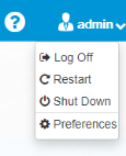
Navigate to Power > Shutdown

Mark all magazines, drives, cables and modules in someway so you can return everything where it belongs in all modules above the CM as well as the CM itself.
- Insert the T8 end of the assembly tool into the magazine release hole until the magazine pops out. Remove the magazine.

- Disconnect the power cables from the power source.
- Disconnect the power cables from the power supplies.
- Disconnect the Ethernet cable.
- Disconnect the SAS or Fibre channel cables from the drives
- Pull out on the pin and slide the module interconnect down.

Depending on how many modules you need to remove, start at the top most module in the rack and remove the attachment screws.
There are two different versions of the chassis available on Scalar i6 systems: Series 1 and Series 2.
Identify Your Chassis Series
- Series 1 - A Series 1 chassis uses screws to attach modules together.
- Series 2 - A Series 2 chassis contains latches on the front and rear of the chassis. These latches are used to attach modules together. A Series 2 chassis is backwards compatible with the Series 1 chassis.
Select from the options below:
-
Remove the two (2) long screws in the holes at the front of the module in the magazine bays using the Torx tool.

- Place the screws aside.
-
Remove the two (2) short screws in the holes at the back of the module in the drive bay using the torque wrench.

- Place screws aside.
- If magazines are in the chassis, remove the magazines to access the front and rear latches in the chassis.
-
There are two latches on the left and right front of the chassis. To unlock, push the latch towards the back of the chassis until it disengages from the front catch.

-
There are two latches on the left and right rear of the chassis. To unlock, pull the latch back until it disengages from the rear catch and the slot indicator on the side frame no longer appears.

Note: The images display yellow alignment pins. Newer modules have blue alignment pins.
-
Find the yellow tab at the front of the module and slide the front alignment pin up out of the hole on the module below.

-
Find the yellow tab at the back of the module and slide the back alignment pin up out of the hole on the module below.

-
Loosen the thumbscrews on the rack mount clamps on each side of the module to be removed.

- Remove the thumbscrews and set them aside.
- Slide the module forward slightly so you can remove the 'ear' of the rack mount clamp from the slots on the side of the module.
- Set the clamps aside.
Using two (2) people, slide the module out of the rack and set on a flat surface.
-
If the CM was located at the top of the library stack, remove the top cover. If the CM was not located at the top of the stack and you had to remove EMs, go to step 2.
 Remove Top Cover
There are two different versions of the top cover available on Scalar i6 systems, one with screws and one without screws.
Select from the options below:
Slide-On Top Cover (No Screws)
- If you did not remove the magazines while unpacking the library, do so at this time.
-
Using the empty magazine slots for access, use both hands to gently push up and forward on the inside of the top cover. This will release the top catch and side stops.

-
Slide the top cover off.

Top Cover With Screws
Required Tools: T-10 Torx Driver (included with library assembly tool)
-
Use the assembly tool to remove the 8 cover screws.

- Remove cover. Be careful not to let the cover sag in the middle or at the ends.
-
Using the lift bar and the lift tab, pull upward until the gears are free from the rack.

-
Set the robot on the module chassis a few inches toward the front.

- Insert cable hold tool.
- Lift the robot cable cover up.
-
Disconnect the robot cable from robot and attach the robot cable to the cable hold tool. DO NOT RELEASE THE CABLE.

- Using the two lift points, set the robot away from the library on a level surface.
-
Using the lift bar and the lift tab, pull upward until the gears are free from the rack.
-
Set the robot on the module chassis a few inches toward the front.
- Insert cable hold tool.
- Lift the robot cable cover up.
-
Disconnect the robot cable from robot and attach the robot cable to the cable hold tool. DO NOT RELEASE THE CABLE.
- Using the two lift points, set the robot away from the library on a level surface.
Remove the following Control Module components as applicable:
-
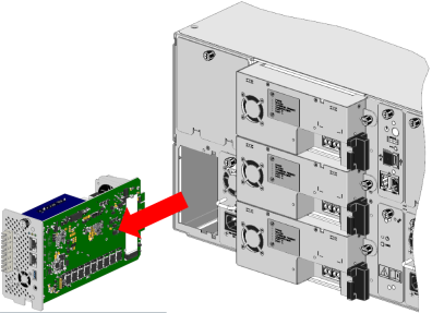
Write down the current iBlade cabling configuration. The cables must be returned to the same locations on the new iBlade.
- Disconnect the cables from the iBlade. This includes drive and Ethernet cables.
-
Loosen the thumbscrew and remove the iBlade from the library.
-
Loosen the drive thumbscrew.

-
On the left side of the drive sled, press the lock lever up and slide the drive out of the drive bay.


-
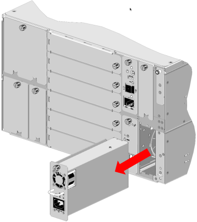
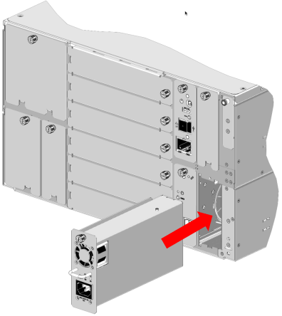
Loosen the SCB thumbscrew.

- Use the thumbscrew to slide the SCB out of the module.
- Loosen the thumbscrew.
- Pull the handle and slide the power supply out of the module.
Required Tools: T-10 Torx Driver (included with library assembly tool)
-
Remove the M3 x 1 screw that holds the magazine eject stop in place.

Item Description 1 M3 x 1 Torx Screw -
Remove the magazine eject stop from the magazine eject stop hole.
-
Repeat steps 1 and 2 for each magazine eject stop.
Install the New Control Module (CM) Chassis
Each module comes in its own box. Any drives and redundant power supplies will come in separate boxes.
- Remove all packing materials. Retain these materials in case you need to ship your library in the future.
- With another person, carefully remove the module and place it on a work space.
- Remove all plastic covering.
- Remove drive bay covers from the back of the module.
-
Place the module on top of the previously placed module.

-
Insert the “ear” of the rack mount clamp in one of the three slots on the side of the library. Choose the slot based on how much of the library you want to extend beyond the front and back of the rack. If your rack has a door, you want to make sure you can close the door when the library is mounted in the rack.

- Screw the 4 thumbscrews through the rack mount clamp slots into the threaded holes in the rack shelves.
Additional Information
- If you are adding the module to another module, don’t tighten the thumbscrews until you’ve aligned and attached the module. When the two alignment pins are down and the four module attachment screws have been tightened, tighten the rack thumbscrews.
- Due to i6 modules being slightly smaller than 6U, in large systems the rack mount claps will eventually stop aligning to the rack and cannot be used. In a full 48U i6 configuration, the top of the rack can be off by approximately .5U. Do not attempt to force align the rack mount clamps.
Note: The images display yellow alignment pins. Newer modules have blue alignment pins.
-
Align the new module with the module below by eye.

-
Using the yellow/blue tab, slide the front alignment pin down into the hole on the module below.

- Using the yellow/blue tab, slide the rear alignment pin down into the hole on the module.
WARNING: Do not use the Module Interconnect to help align the modules. Work to get the alignment pins engaged before moving on to next steps.
There are two different version of the chassis available on the Scalar i6 system: a Series 1 chassis and Series 2 chassis.
Identify Your Chassis Series
- Series 1 - A Series 1 chassis uses screws to attach modules together.
- Series 2 - A Series 2 chassis contains latches on the front and rear of the chassis. These latches are used to attach modules together. A Series 2 chassis is backwards compatible with the Series 1 chassis.
-
To attach the module to the module below, use the two (2) long screws in the holes at the front of the module in the magazine bays.
Caution: Tighten using the Torx. Do not use the torque wrench.
-
To attach the module to the module below, use the two (2) short screws in the holes at the back of the module in the drive bay

-
Insert a short screw into the screw holder on the assembly tool.

-
Use the screw holder and the assembly tool torx wrench to get the rear screws started.

-
Pull straight back on the tool to release the screw.

-
Tighten the screw until you hear a click, or until you feel the torx wrench slip in the torque wrench. When it clicks or slips, the screw is torqued to 10 inch pounds.

-
If magazines are in the chassis, remove the magazines to access the front and rear latches in the chassis.
-
There are latches on the left and right front of the chassis. To lock, pull the latch towards the front of the chassis until it lifts and engages the front catch.

-
There are latches on the left and right rear of the chassis. To lock, push the latch forward until it moves down and engages the catch. A slot indicator on the side frame will also appear behind the latch when it is fully engaged into the catch.
Important Information - Bottom Module Latches
Do not lock the rear latches of the chassis containing the bottom cover in the module stack. The latches will interfere with tape drives being properly set into the chassis.

-
Pull out on the pin and slide the module interconnect up.

-
Tighten the rack thumbscrews on the module you just added.

-
If the cable spool bay cover is installed, loosen its thumbscrew and remove it.

-
Insert the T8 end of the assembly tool into the left magazine release hole until the magazine pops out. Pull the magazine out about two inches.

-
Attach the cable spool feed tool to the robot cable connector.

-
Slide the cable spool into the library until you feel the feel the electrical connection slide in to place.
- Tighten the thumbscrew until finger tight.
-
Gently pull the cable feed tool up until the robot cable is out of the library.

-
Attach the robot cable to the cable hold tool.

-
Tighten the cable spool thumbscrew.

- Insert the right magazine into the library until it locks in to place.
-
Using the two lift points, place robot on top of library.

-
Connect the robot cable to the robot.

- If the cable hold tool is present, remove it.
-
Close the robot cable cover until it clicks into place.

-
Align the robot gears with the library rails. Push down on the lift tab and the lift bar until the robot is lower than the top of the module frame.
Caution: Do not push down on the robot anywhere other than the identified touch points. Damage to robot may occur.

-
If the CM is at the top of the library stack, replace the top cover. If the CM is not at the top of the library stack, go to Step 9.
Replace Top Cover
There are two different versions of the top cover available on Scalar i6 systems, one with screws and one without screws.
Slide-On Top Cover (No Screws)
-
If the top cover is new, remove the plastic wrap from the cover.

-
Hold the cover with the top catch facing towards you.
-
Slide the cover on top of the module until the side stops and top catch lock the cover into place.

- Insert the magazines back into their slots.
Top Cover With Screws
Required Tools: T-10 Torx Driver (included with library assembly tool)
-
Place the cover on top of the module and attach using the screws.
-
-
Slide the iBlade approximately ¾ of the way into the library.
Caution: Do not slide the iBlade all the way into the slot.
-
Using the cabling list you created earlier, reconnect the cables to the iBlade exactly as they were before.
- Slide the iBlade in until you feel the iBlade connector slip into the library connector.
- Tighten the iBlade thumbscrew.
-
Slide the drive gently into the drive bay until the lock lever is in the down position.
-
Tighten drive thumbscrew.
-
Attach the FC cable to the drive.

-
Gently slide the SCB into it's slot in the library until you feel the electrical connection slide in to place.

- Tighten the SCB thumbscrew until finger tight.
- Slide the power supply into its slot until the front bezel is sitting flush against the back of the module.
- Tighten the thumbscrew until finger tight.
Required Tools: T-10 Torx Driver (included with library assembly tool)
Important Information
Install the magazine stops one at a time. This will ensure the electronics behind the bezel stay in place.
-
Remove the plug above the magazine eject button.

Item Description 1 Airgap Magazine Eject Stop Hole - Remove the screw from the magazine eject stop hole.
-
Install the magazine eject stop into the hole. The arrow should be pointing towards the center of the module.

Item Description 1 Airgap Magazine Eject Stop -
Insert the M3 x 1 screw provided with the magazine eject stops into the magazine eject stop hole and tighten.
Item Description 1 M3 x 1 Torx Screw -
Repeat steps 1-3 for each magazine eject stop.
Depending on your library stack configuration, you may need to re-stack one or more Expansion Modules (EMs) that were removed from the library stack during this replacement procedure. Repeat Steps 3 - 6 to re-stack each EM.
Once all modules are installed and attached, install the magazines in the replacement CM. The magazines must be placed back in the same bay location they resided in the original CM.
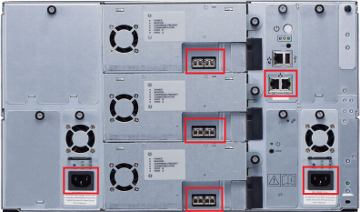
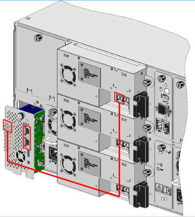
- Connect Fibre Channel drives with Fibre Channel cables. Connect SAS drives with SAS Mini HD cables (Callout 2 below)
- Plug the 90 degree connector into the primary power supply’s power connector (Callout 3 below)
- Plug the 90 degree connector into the redundant power supply’s power connector (Callout 4 below)
- Plug the primary power supply connector into a power source. The library will begin to initialize (Callout 5 below).
- Plug the redundant power supply connector into a power source. If possible, the redundant power supply should be connected to a power source on a different circuit (Callout 6 below).
Note: If the power supply connectors are plugged into a hot power source, the library should power on. If the library does not power on, push the power switch on the SCB.

The replacement CM contains a new serial number. Before operating the library with a new CM, you must install new library licenses that are configured for the new serial number.
Additional Information
- You can view the current status of your licenses at www.quantum.com/licensekeys
- Contact Quantum Service and Support to obtain new licenses for your library system.
This window allows you to enter additional license keys to activate specific features available for your library.

- From the Navigation panel in the WebGUI, select Licenses.
-
In the Operations panel, click Add.
Item Description Action License Key Allows you to enter a license to activate a feature.
Enter the license key provided on the feature license certificate. -
Click Apply to save your settings.
-
Click Close to exit the window.
Restore your library configuration using the saved library configuration created in Remove the Control Module Chassis - Step 1.
| Item | Description | Action |
|---|---|---|
| Restore Configuration |
Restores library to the selected configuration. After the restore, the library will automatically reboot. |
Select the radio button. |
| Restore Filename | Allows you to select the name of the library configuration file you want to restore. | Click the Browse button and navigate to the configuration file you want to use. Click Apply to begin restoring the library configuration. |
| Save Configuration | Saves the current library configuration. | Select the radio button. Click Apply. The library configuration file is downloaded. You can then use the file locally or email it. |
Click Close to exit the window.
IVT is a diagnostic test that verifies basic library functionality. It performs a complete library installation test to verify robotic operation within the current library configuration. IVT tests determine proper installation and operation by performing robotic self tests, by scanning tape cartridges, and performing GET/PUT tape cartridge tests at storage slot, I/E slot, and drive sled locations.
IVT uses existing tape cartridges for in-place GET/PUT testing, and moves a scratch tape to empty locations to verify proper slot and/or drive sled accessibility.
A complete IVT should be run as part of the installation process.
IVT Prerequisites
Review the following before running an IVT test:
- The library should have no unresolved RAS tickets.
- The library WebGUI accurately reflects the actual number of modules and drives in the system.
- The library is in a READY state all magazines are properly inserted.
- A scratch tape must be provided and placed into the first slot of the configured I/E area (Control Module's top right magazine, first column, bottom slot). If an I/E area is not configured, this slot position will be used by the library to locate the scratch tape, even if this slot is assigned as a storage slot to a partition.
-
Do Not use any cleaning tape as an IVT scratch tape. The IVT may fail due to timeout conditions.
- Do Not use an uncalibrated LTO-9 tape as an IVT scratch tape. If you do, the test will immediately fail and the drive will continue to calibrate the tape until it is complete. You will then need to manually remove the (now calibrated) tape and re-run IVT.
- If you do not have a calibrated LTO-9 scratch tape to run IVT, vary off the LTO-9 drives (see Vary Drive On or Off). This will prevent the test from failing due to LTO-9 calibration operations.
In addition to the prerequisites above, Quantum recommends that the scratch tape is read-capable by all drive generations in the library. If the tape cartridge media generation is not supported by a drive generation in the library, drive tests are skipped. The skipped drive tests will then need to be repeated with a scratch tape of compatible read format.
-
Press the right magazine release button on the Control Module (CM). The magazine will “pop” out. Pull the magazine until the first set of slots is exposed.

-
Insert a scratch tape. A scratch tape is a blank tape or one you don’t mind being overwritten. Insert the tape into the bottom front slot in the right magazine. This is the designated I/E slot for the library.

-
Select Diagnostics from the WebGUI menu.

- Select the Installation Verification Test checkbox from the North Panel.
-
Click the Test button in the Operation Panel. The Installation Verification Test window displays.

- The Complete IVT radio button should be pre-selected. If it’s not, select it.
-
Click Apply. The Progress area of the dialog window will display the test progress.
Note: You must wait until the library has finished initialization before you can begin the IVT process.
-
The results of each of the IVT tests displays in the Progress area.
Caution: The library will display a Ready status during IVT. Disregard and do not try and perform any library operations. When each Magazine Test is complete, the library will be ready.