What is a CRU?
CRU stands for Customer Replaceable Unit. A CRU is a library component that can be installed or replaced by the owner of the library. The Scalar i6 library was designed so that most service functions can be performed by the owner.
This section gives you more detail about the CRUs in the Scalar i6 library.
The System Control Blade (SCB) is the main controller for all library operations. It contains the user interface operations, Web Services, and it stores the configuration.
The SCB is located in the Control Module (CM).
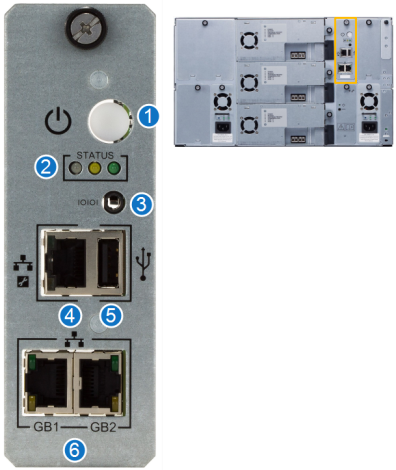
| Item | Name | Description |
|---|---|---|
|
1 |
Power Switch | The power switch initiates the shutdown procedure when you press it for two seconds. If you press it for five seconds, you will force a hard shutdown. It is solid green and illuminated when the library is powered on. |
| 2 | Status LEDs |
Normal indications:
|
| 3 | Serial Port | The serial port is for engineering use only. |
| 4 | Service Port | The service port allows you to connect directly to the library to perform service functions. |
| 5 | Service USB | The service USB port is not used at this time. |
| 6 | Ethernet Ports |
The Ethernet ports allow you to connect the library to a network. This allows you to connect to hosts and to configure and operate the library through the WebGUI. While the ports are identical in function, use Gb1 as your primary network connection and Gb2 as your secondary connection. There are two for redundancy. GB1 and GB2 correspond to the interface settings in the Scalar i6 Network Settings menu. |
Every Scalar i6 library module that contains tape drives
If the library has two power supplies, one power supply can be replaced with power applied to the other power supply, but doing so will produce a RAS ticket.
Additional Information
- Library modules that contain both an iBlade and tape drives must have two power supplies installed.
- The power supply is highly efficient, rated at 80 PLUS®, a performance specification that requires an 80% or higher energy efficiency at 10, 20, 50 and 100% of rated load with a true power factor of 0.9 or greater.
- The power supply connects to an outside power source and converts the input power to the AC and DC voltages used by the library components.
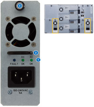
| Item | Name | Description |
|---|---|---|
|
1 |
LEDs |
Power Supply LEDs provide you with visual information that let you know the power supply is working correctly. Normal indications:
If the Fault LED is solid blue, or if the other two LEDs are off, you should check for RAS tickets to learn how to resolve the problem. |
| 2 | Handle | Used to remove and install the power supply. |
| 3 | Thumbscrews | Used to secure the power supply to the chassis. |
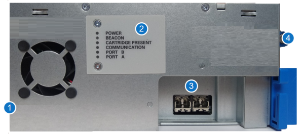
Tape drives are installed in the back of the library. The Scalar i6 supports up to three IBM Fibre Channel (FC) LTO-6 and later
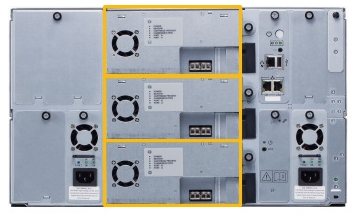
LTO-8 FC Drive
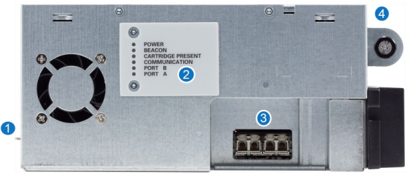
LTO-9 FC Drive
LTO-9 SAS Drive
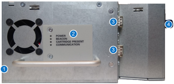
| Item | Name | Description |
|---|---|---|
|
1 |
Unlock Lever |
The unlock lever must be pushed to the unlocked (up) position before the drive sled can be removed from the library. |
| 2 | LEDs |
The drive LEDs provide you with visual information that lets you know the drive is working correctly. After the library is powered up and working, the following indications tell you the drive is operating normally:
|
| 3 | Ports | The ports connect your drives to a server or a switch. You connect Fibre Channel drives with Fibre Channel cables. |
| 4 | Thumbscrews | Thumbscrews secure the drive sled to the chassis. |
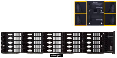
The Scalar i6 has two removable magazines. Each magazine holds up 25 LTO tapes. The tapes fit inside the individual magazine slots. You can assign slots as I/E slots through the WebGUI.
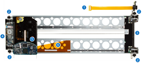
| Item | Name | Description |
|---|---|---|
|
1 |
Robot Cable |
Provides the electrical connection between the robot and the SCB. |
| 2 | Gears |
Provides the Y-Axis movement – vertical movement. The gears also provide an alignment reference when replacing the robot. |
| 3 | Lift Bar | You use the lift bar in conjunction with the lift tab to handle the robot when removing or replacing the robot. |
| 4 | Lift Tab | You use the lift tab in conjunction with the lift bar to handle the robot when removing or replacing the robot. |
| 5 | Robot Picker | The mobile part of the robot that moves media between slots and drives. |
| 6 | Ribbon Cable | Provides connectivity to the robot picker. |
The cable spool provides the electrical connection between the robot and the System Control Board. The cable spool allows the robot cable to feed out and retract back in as the robot moves up and down in the library.
The cable spool is only installed in an Expansion Modules (EMs). Scalar i6 Control Module (CM) only installations do not require a cable spool.
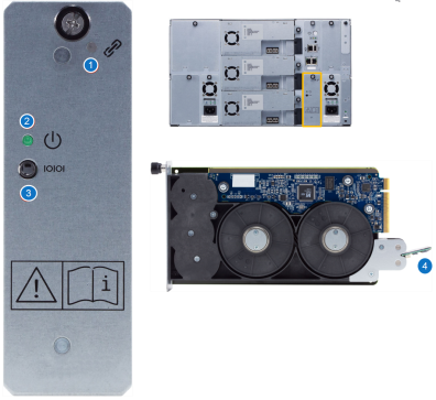
| Item | Name | Description |
|---|---|---|
|
1 |
This indicator is for future use. |
|
| 2 | Robot Power LED |
This indicator illuminates green when power is being supplied to the robot. |
| 3 | Serial Port | This serial port is for engineering use only. |
| 4 | Robot Cable | This cable attaches to the robot and feeds out and retracts in as the robot moves. |
The Scalar iBlade is a converged server platform for the Scalar
| Veeam Tape Server iBlade |
The Veeam Tape Server option eliminates the need for a dedicated external physical tape server. The Veeam Tape Server comes with Windows 2016 pre-installed. The customer provides and loads the Veeam software during installation. Caution: This is the only software that may be loaded on the Veeam Tape Server. |
| SLTFS/NAS iBlade | The SLTFS/NAS option creates a NAS tape archive for file-based unstructured data storage with integrated SLTFS. The SLTFS/NAS iBlade comes with CentOS and SLTFS software installed. The SLTFS iBlade is sometimes called the “LTFS iBlade.” |
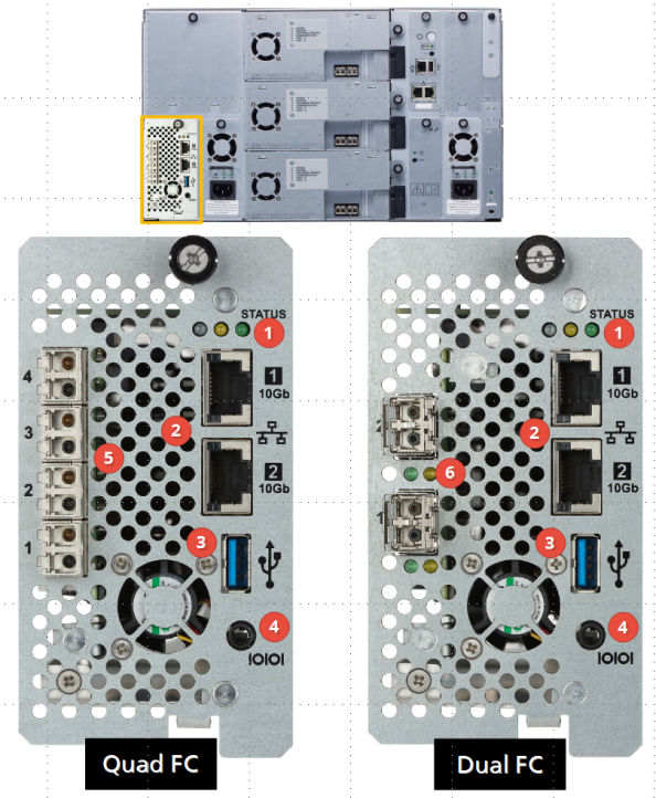
| Item | Name | Description |
|---|---|---|
|
1 |
Status LEDs |
Indicates the operating status of the iBlade. SLTFS/NAS iBlade normal indications:
SLTFS application not running:
Veeam Tape Server iBlade normal indications:
|
| 2 | Ethernet Ports | These are two dual speed 1Gb/10Gb Ethernet ports. These connect to the LAN/WAN and are used for data ingest and software installation. |
| 3 | USB Port | Reserved for Quantum engineering and manufacturing. |
| 4 | Serial Port | Reserved for Quantum engineering and manufacturing. |
| 5 | Quad Fibre Channel Connectors (16 Gbs) | Connects to up to four (4) FC drives. |
| 6 | Dual Fibre Channel Connectors | Connects to up to two (2) FC drives |
