minute read
Replace DXi T10 NVMe SSD Drives
Overview
DXi T10-60 supports 6 2.5" NVMe 15 TB SSD storage drives in toolless drive carriers to simplify their removal from the chassis. These carriers also help promote proper airflow.

DXi T10-120 supports 10 2.5" NVMe 15 TB SSD storage drives in toolless drive carriers to simplify their removal from the chassis. These carriers also help promote proper airflow.

DXi T10-240 supports 10 2.5" NVMe 30 TB SSD storage drives in toolless drive carriers to simplify their removal from the chassis. These carriers also help promote proper airflow.
DXi T10-480 supports 10 2.5" NVMe 60 TB SSD storage drives in toolless drive carriers to simplify their removal from the chassis. These carriers also help promote proper airflow.
RAID 6
The 10 (DXi T10-120) or 6 (DXi T10-60) external NVMe SSD drives utilizes a RAID 6 configuration. The external drive slots are numbered in the RAID as follows:

A RAID 6 configuration can tolerate up to two disk failures. More than two disk failures can result in data loss.
Drive LED Information
Each 3.5" NVMe drive has two LED indicators: an activity indicator and a status indicator. These are used to indicate the status of the drives as shown in the table below.
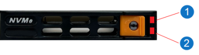
| Item | LED | LED Color | State | Status |
|---|---|---|---|---|
|
1 |
Activity LED |
Blue | Solid On | NVMe drive installed |
| Blue | Blinking | I/O activity | ||
|
2 |
Status LED | Red | Solid On | Failed drive |
| Red | Blinking at 1 Hz | Rebuild drive | ||
| Red | Blinking with two blinks and one top at 1 Hz | Hot spare | ||
| Red | On for five seconds, then off | Power on | ||
| Red | Blinking at 4 Hz | Identify drive | ||
| Red | Solid On | Safe to remove drive | ||
| Green | Blinking at 1 Hz | Attention state - do not remove drive. |
Replacement Procedure
Required Tools: There are no tools required for this component replacement.
Note: This component is hot-swappable. You do not need to stop all I/O from clients or remove power to replace this component.
Take ESD precautions when performing this replacement
The chassis is designed to dissipate all electrostatic discharge (ESD) to the chassis base. Ensure that there is sufficient electrical and mechanical connection from the chassis base to the rack rails, and that the rack itself is tied to earth ground. The unit must be grounded in accordance with all local/regional and national electrical codes.
Some components within the node contain static-sensitive parts. Precautions must be taken to ensure that the system is not exposed to ESD while handling components or servicing the unit. To avoid damaging these parts while performing maintenance procedures, always observe the following precautions:
-
Keep static-sensitive parts in their original shipping containers until ready for installation.
-
Do not place static-sensitive parts on a metal surface. Place them inside their protective shipping bag or on an anti-static mat.
-
Wear anti-static wrist bands when unpacking and handling the units, and avoid touching connectors and other components.
-
Dry climates and cold-weather heating environments have lower relative humidity and are more likely to produce static electricity.
-
Before removing the SSD drive, remove the drive from the software RAID. You can remove the disk using the Remote Management Console or CLI.
 Remove Disk - CLI
Command
syscli --remove disk --slot <number> [--sure]
Command Attributes
Review the following attribute descriptions.
‑‑remove diskRemoves a disk from the RAID set.
‑‑slot <number>Disk's slot number.
‑‑sureIf specified, the CLI executes the command without prompting for confirmation.
Remove Disk - Remote Management Console
Note: The remove disk feature is for external drives only.
To remove a disk:
-
To access the Hardware page, click the Utilities menu, and then click the Hardware tab.
-
Select the failed disk in the table to be removed from the RAID. The disk will have a status of Failed.
-
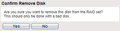
Click the Remove button. A dialog box appears asking if you want remove the disk from the RAID. Click Yes.
After removing a failed disk, the disk's status will no longer be available through the software RAID. Until the failed drive is physically removed from the system and replaced with a new drive, the failed disk status will appear as New in the NVMe Drive Replacement table.
-
-
Release the SSD drive from the system:
Note: Drives come pre-installed in drive carriers, so there is no need to remove the failed drive from its carrier when removing from the system.
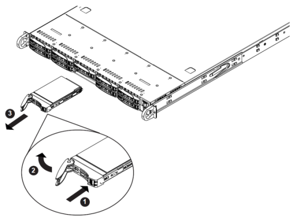
-
Push the release button on the drive carrier (1 in image above).
-
Swing the handle fully out (2 in image above).
-
Grasp the handle and use it to pull the drive carrier out of its bay (3 in image above).
Note: Drives come pre-installed in drive carriers, so there is no need to remove the failed drive from its carrier when removing from the system.
-
Obtain the new data SSD drive and carrier.
-
Insert the drive carrier into its bay:
Note: Keep the carrier oriented so that the hard drive is on the top of the carrier and the release button is on the right side. When the carrier reaches the rear of the bay, the release handle will retract.
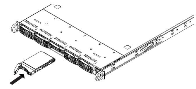
-
Push the handle in until it clicks into the locked position, indicating the drive is fully seated in the system.
-
Add the replacement drive back into the software RAID. You can add the disk using the Remote Management Console or CLI.
Add Disk - CLI
Command
syscli --add disk --slot <number> [--sure]
Command Attributes
Review the following attribute descriptions.
‑‑add diskAdds a disk to a RAID.
‑‑slot <number>Disk's slot number.
‑‑sureIf specified, the CLI executes the command without prompting for confirmation.
Add Disk - Remote Management Console
The Add button will add a disk the software RAID that is not currently a part of the RAID. A disk that is not currently part of the software RAID will have a status of New.
To add a disk:
-
To access the Hardware page, click the Utilities menu, and then click the Hardware tab.
Select the disk in the table to be added to the RAID. The disk will have a status of New.
-
Click the Add button. A dialog box appears asking if you want to add the disk to the RAID. Click Yes.
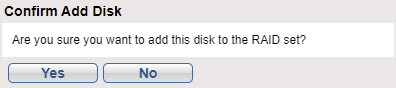
Once the disk has been added to the RAID, the drive will have a status of Healthy.
-