minute read
Replace DXi T10 Network Adapter Card
Overview
The DXi T10 1U12 chassis can contain up to two full-height and one half-height network adapter cards. The possible card configurations are below:

| PCIe | 100 GbE Ethernet Card | 10/25 GbE Ethernet Card | 32 Gb Fibre Channel Card |
|---|---|---|---|
| 1 | No | Yes | Yes |
| 2 | Yes | Yes | Yes |
| 3 | Yes | Yes | Yes |
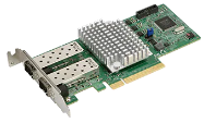
10/25 GbE Ethernet Dual-port Card
This card provides two 10/25 GbE (SFP28 optical or DAC copper) Ethernet ports.
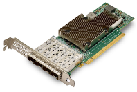
10/25 GbE Ethernet Quad-port Card
This card provides four 10/25 GbE (SFP28 optical or DAC copper) Ethernet ports.
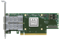
100 GbE Ethernet Dual-port Card
This card provides two 100 GbE (SFP28 optical or DAC copper) Ethernet ports.
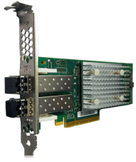
32 Gb Fibre Channel dual-port cards.
This card provides two 32 Gb Fibre Channel ports.For path to tape and VTL.
Replacement Procedures
Follow the instructions below to replace the network adapter cards.
WARNING: Failure to follow the correct installation procedure will cause the replacement card to be inoperative.
Required Tools: There are no tools required for this component replacement.
Take ESD precautions when performing this replacement
The chassis is designed to dissipate all electrostatic discharge (ESD) to the chassis base. Ensure that there is sufficient electrical and mechanical connection from the chassis base to the rack rails, and that the rack itself is tied to earth ground. The unit must be grounded in accordance with all local/regional and national electrical codes.
Some components within the node contain static-sensitive parts. Precautions must be taken to ensure that the system is not exposed to ESD while handling components or servicing the unit. To avoid damaging these parts while performing maintenance procedures, always observe the following precautions:
-
Keep static-sensitive parts in their original shipping containers until ready for installation.
-
Do not place static-sensitive parts on a metal surface. Place them inside their protective shipping bag or on an anti-static mat.
-
Wear anti-static wrist bands when unpacking and handling the units, and avoid touching connectors and other components.
-
Dry climates and cold-weather heating environments have lower relative humidity and are more likely to produce static electricity.
-
Remove power from the DXi T10 system node.
-
Hold down the power button for at least 4 seconds.
Note: The power button applies or removes primary power from the power supply to the node but maintains standby power. Once the node has powered down, unplug the power cords to the node power supplies to remove all power.
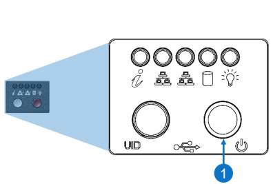
Item Description 1 Power Button
-
-
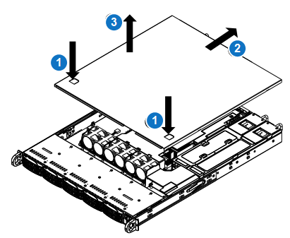
Remove the chassis cover to access the modules on the motherboard.
-
Grasp the two handles on either side and pull the unit straight out until it locks (you will hear a "click").
-
Depress the two buttons on the top of the chassis to release the top cover and at the same time, push the cover away from you until it stops.
-
Lift the top cover from the chassis to gain full access to the inside of the server.
-
-
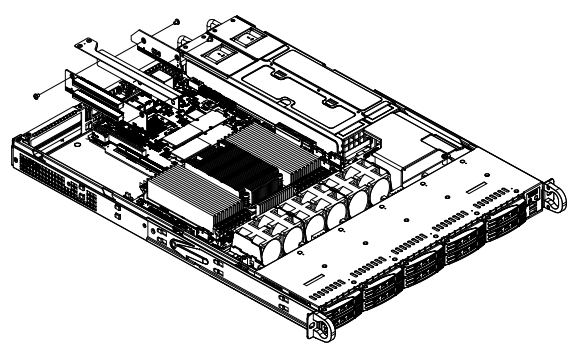
Remove the riser card bracket from the chassis by unscrewing the screws indicated in the figure below.
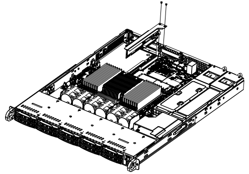
-
Lift the riser card bracket from the chassis.
-
Install the riser card on the bracket with the two screws provided.
-
Open the latch on the end of the bracket.
-
Remove the expansion card by sliding the card out of the appropriate slot in the riser card.
-
Install the replacement expansion card by sliding the card into the appropriate slot in the riser card, and then close the bracket latch over the end of it.
-
Install the entire assembly into the appropriate slot on the server board while aligning the bracket in the rear of the chassis.
-
Install the chassis cover.
-
Power the system node back on.
-
Plug the power cords into the rear of the power supplies.
-
Press the power button once. The server control board will initiate the power up sequence.
Item Description 1 Power Button
-