minute read
DXi T10 Node Features and Indicators
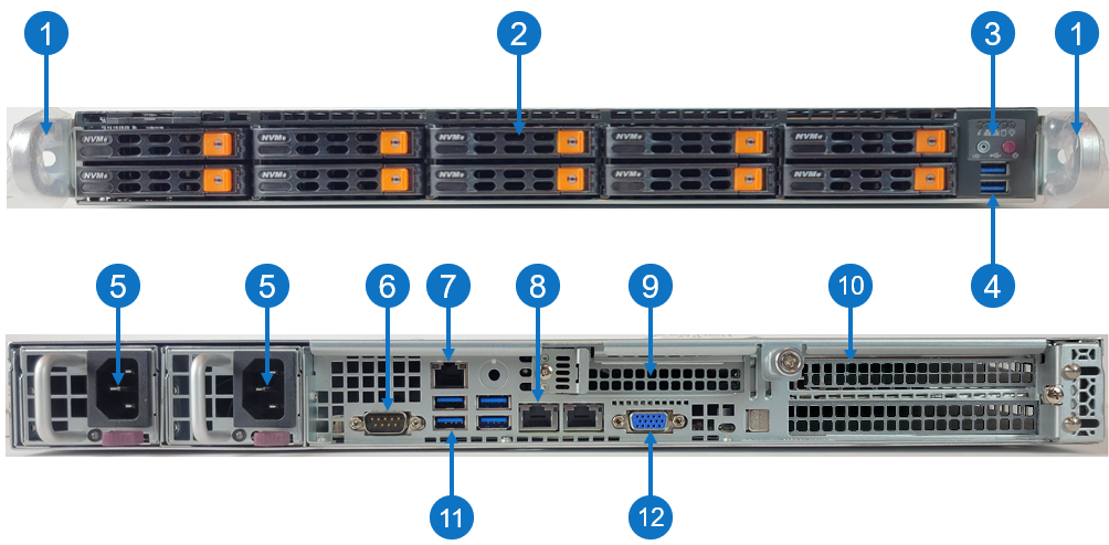
The controls, indicators, and connectors are located behind the optional rack bezel on the front panel of the DXi T10 Node.
DXi T10 - Front and Rear
| Item | Description |
|---|---|
| 1 |
Front handles WARNING: Do not pick up the node with the front handles. They are designed to pull the system from a rack only. |
| 2 | (10) 2.5" NVMe drive (15 TB SSD) |
| 3 | Control panel |
| 4 | (2) USB storage port |
| 5 |
(2) 750W Hot-swappable redundant, load-sharing AC power supply unit (PSU)
|
| 6 | COM port |
| 7 | RJ-45 100/1000BASE-T IPMI port |
| 8 | (2) RJ-45 100/1000BASE-T management ports (left port # 1 and right port # 2) |
| 9 |
1 Expansion card slot for low-profile, half-height expansion (add-on) card
|
| 10 |
2 Expansion card slots for low-profile, full-height expansion (add-on) card
|
| 11 | (4) USB storage port |
| 12 | VGA port |
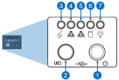
Control Panel
| Item | LED/Button | Description |
|---|---|---|
| 1 | Power Buttom |
Use the main power switch to apply or remove power to the node. If you turn off the system power with this button, then the process removes the main power but keeps standby power supplied to the node.
Caution: You must unplug the AC power cord before you service the node. |
| 2 | Unit identifier (UID) button |
Press the button to illuminate an LED on both the front and rear of the node for easy system location in a rack configuration. The LED remains on until the button is pushed a second time. Blue: Solid, unit identified None: Off, UID is off Note: A UID button on the rear of the node serves the same function. |
| 3 | Universal information |
|
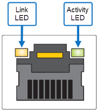
| 4 | 10/100/1000BASE-T RJ-45 port |
Indicates network activity on the management port # 1. The physical port LEDs represent the following:
Link LED
Activity LED
|
| 5 | 10/100/1000BASE-T RJ-45 port |
Indicates network activity on the management port # 2. The physical port LEDs represent the following:
Link LED
Activity LED
|
| 6 | When flashing, indicates drive activity. | |
| 7 | Indicates power is supplied to the system's power supply units; this LED illuminates when the system is operating normally. |