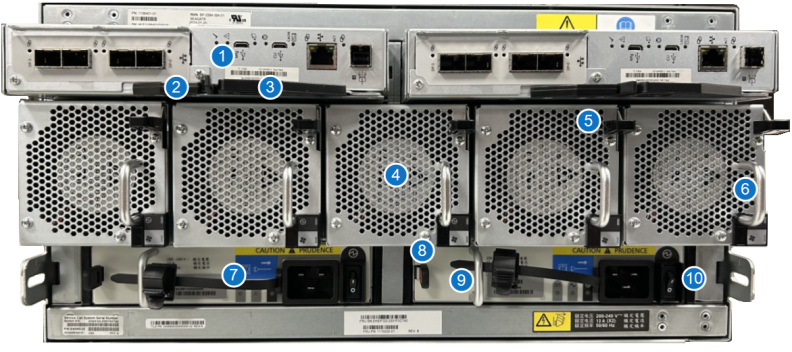
Array Module Rear Panel Features and Indicators
DXi Array Module – Rear Panel
LED indicators and buttons are located on the back of the Array modules (RBODs).

| Item | Indicator, Button, or Connector | Description |
|---|---|---|
| 1 | Controller module (CM) | Provides data redundancy and is the nerve center of the storage enclosure. |
| 2 | CM release latch | Provides full contact with midplane or releases CM for inspection and service. |
| 3 | CM release latch and handle | |
| 4 | Fan cooling module (FCM) | Provides redundant regulation of temperature and airflow |
| 5 | FCM release latch | Provides full contact with midplane or releases FCM for inspection and service. |
| 6 | FCM pull handle | |
| 7 | Power supply unit (PSU) | Provid.es redundant regulation of power |
| 8 | PSU release latch | Provides full contact with midplane or releases PSU for inspection and service. |
| 9 | PSU pull handle | |
| 10 | PSU power switch | Powers on or off the storage enclosure. |
DXi Array Module – Control Module

| Item | Indicator, Button, or Connector | Description |
|---|---|---|
| 1 | SCSI ports | SCSI ports data exchange with DXi9200 Node. |
| 2 | USB port | Manufacturing Universal Serial Bus (USB) port: do not use |
| 3 | USB port | CLI port: do not use. |
| 4 | Ethernet port | Ethernet connection to DXi Node. |
| 5 | SAS expansion port | SAS expansion 12Gb/s data exchange with other expansion enclosures. |
DXi Array Module – Control Module Fault LEDs
|
LED |
Type |
Color |
State | Status |
|---|---|---|---|---|

|
SCSI port | Amber | On | Critical cable fault. |
| Fast flash* (1s on, 1s off) | Unit identification (UID) active. | |||
| Slow flash* (3s on, 1s off) | Non-critical cable fault. | |||
| Off | Port functioning properly. | |||

|
Hardware fault | Amber | On | CM hardware fault. |
| Fast flash (1s on, 1s off) | Part of sequence as CM comes online. | |||
| Off | CM functioning properly. | |||

|
OK to remove | White | On | Ready for removal, the cache is clear. |
| Off | Do not remove the CM, cache still contains unwritten data. |
