minute read
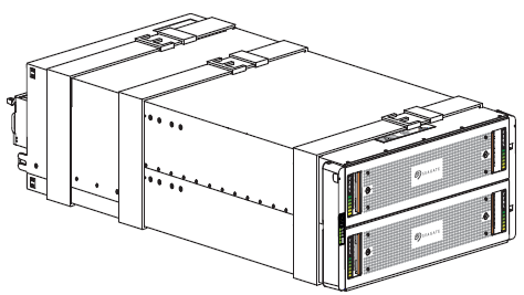
DXi9200 Rack Mount Rails Replacement
Overview
Follow the steps in this document to replace the Node and Array Module (RBOD0 rack mount rails in the DXi9200.
Necessary Tools
Before you begin, gather the necessary tools:
- Small flat head screwdriver
- Large flat head screwdriver
- #2 Phillips screwdriver
Caution: Use appropriate ESD precautions, including the use of a grounding strap, when performing any of these procedures.
DXi9200 Node Rails
Note: Download the system logs from the Utilities > Diagnostics > System Diag File page before shutting down. This will provide a record of the system prior to any hardware configuration changes.
-
Shut down the system from the remote management console using the Shutdown option on the Utilities > Reboot & Shutdown page.
Note: Shutting down the system can take up to 15 minutes. Only the Node will completely shut down.
-
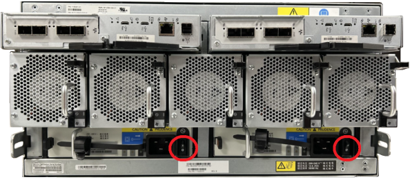
After the Node shuts down, remove power from the Array module(s). Press the power switch to the OFF position for each PSU.
Caution: Never remove power from a redundant power supply unit (PSU) when the other PSU has a fault condition, indicated by an amber LED.
Array Module (RBOD) Power Switches

-
Disconnect each power connector from its PSU socket or from the PDU.
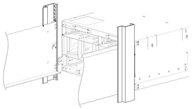
To remove the DXi9200 Node from the rack:
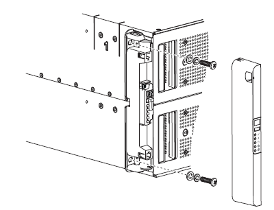
- If installed, remove the front bezel from the Node by lifting the latch on the left side of the bezel.
- Remove all power and network cables from the rear of the Node. Make sure to label the cables so they can be easily identified when they are re-connected to the Node after the replacement procedure is complete.
-
Press the locking tab on either side of the Node, and slide the Node out from the rack until the inner rails lock.
Caution: Do not use excessive force when pulling the chassis forward to fully extend the Node or Expansion Module in the rack rails. Using excessive force could bypass the slide rail stop mechanism.
Note: If necessary, remove the optional screws securing the Node to the front of the rack (behind the locking tab).
-
Locate the lock levers on the sides of the inner rails. Unlock each lever by rotating it up to its release position.
- Grasp the sides of the Node firmly and pull it forward until the rail standoffs are at the front of the J-slots.
-
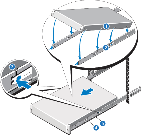
Lift the Node up and away from the rack and place it on a level surface.
WARNING: The DXi9200 Node (including hard drives) weighs 79.6 lbs (36.1 kg. A minimum of two people are required to lift the chassis.
-
Use a flat head screwdriver to lift the latch release button on the end piece midpoint and unseat each rail, and then remove the rails from the rack.
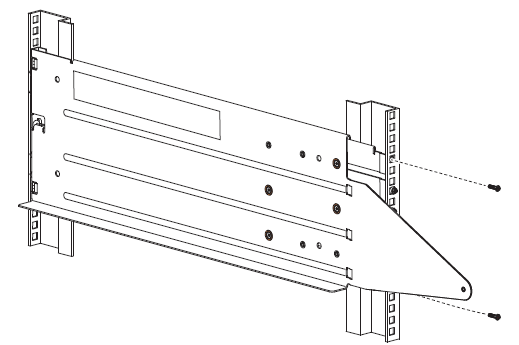
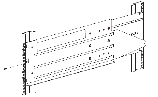
To install the replacement DXi9200 Node rack mounting rails:
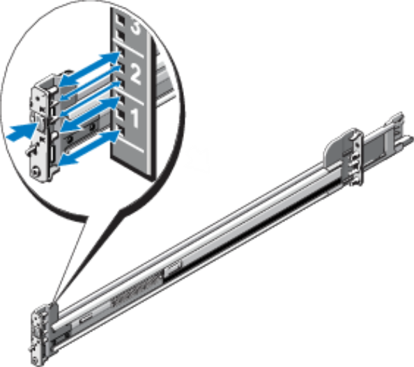
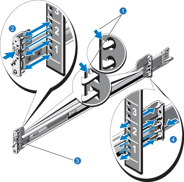
- Position the left and right rail end pieces labeled FRONT facing inward, and orient each end piece to seat in the holes on the front side of the vertical rack flanges.
- Align each back end piece in the bottom and top holes of the desired U spaces.
- Engage the back end of the rail until it fully seats on the vertical rack flange and the latch clicks into place. Repeat these actions to position and seat the front end piece on the vertical rack flange.
To install the DXi9200 Node:
-
Pull the inner slide rails out of the rack until they lock into place.
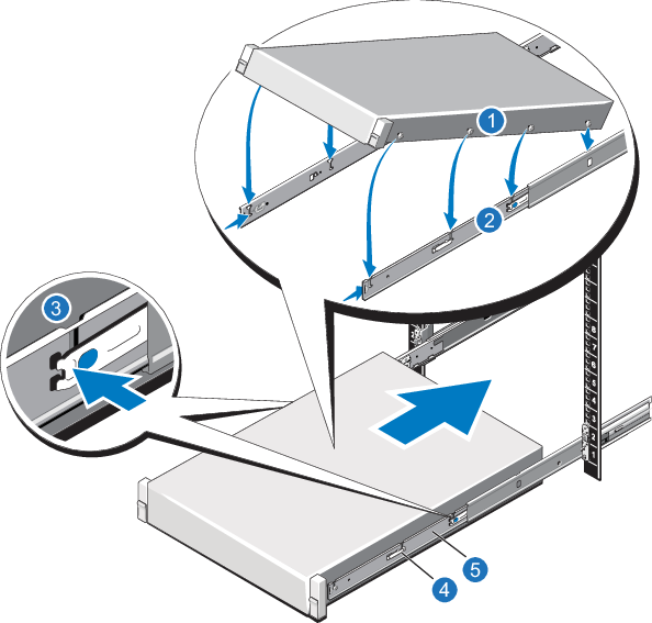
- Locate the rear rail standoff on each side of the system and lower them into the rear J-slots on the slide assemblies.
- Rotate the system downward until all the rail standoffs are seated in the J-slots.
- Push the system inward until the lock levers click into place.
- Press the slide-release lock buttons on both rails and slide the system into the rack.
- Reconnect all power and network cables on the rear of the Node.
- If applicable, replace the front bezel. Insert the right side of the bezel into the slots on the right side of the Node, then snap the left side of the bezel into place.
Power on the DXi9200 system components in the following order:
-
Turn on both power switches on the back of the Array module (RBOD). Facing the front, observe the LEDs on the front panel area and confirm the Power On LED is in a steady green state.
Additional Information
- Check that all drives are correctly seated in all enclosures before powering on the node.
- After powering on the system, do not remove any hard drives. If you accidentally remove a drive, wait 30 seconds before reinserting the drive.
-
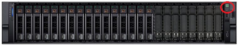
Press the power button on the front of the Node. Wait for the system to boot before continuing with the procedure. (This can take up to 10 minutes.)
Powering on the Array (RBOD) Modules
Powering on the Node
DXi9200 Array Module (RBOD) Rails
Note: Download the system logs from the Utilities > Diagnostics > System Diag File page before shutting down. This will provide a record of the system prior to any hardware configuration changes.
-
Shut down the system from the remote management console using the Shutdown option on the Utilities > Reboot & Shutdown page.
Note: Shutting down the system can take up to 15 minutes. Only the Node will completely shut down.
-
After the Node shuts down, remove power from the Array module(s). Press the power switch to the OFF position for each PSU.
Caution: Never remove power from a redundant power supply unit (PSU) when the other PSU has a fault condition, indicated by an amber LED.
Array Module (RBOD) Power Switches
-
Disconnect each power connector from its PSU socket or from the PDU.
WARNING: The DXi9200 Array module each weigh 180 lbs (81.6 kg) empty. Do not lift the storage enclosure without a mechanical lift.
-
Remove all power cables, Ethernet, and DAC cables from the rear of the Array Module. Make sure to label the cables so they can be easily identified when they are re-connected to the module after the replacement procedure is complete.
-
Complete the following actions on the 5U chassis:
-
Remove and set aside the operator's (ops) panel.
-
Facing the front of the enclosure, remove the Panhead 10-32 screw with washers into the top and bottom holes in the ops panel.
-
Repeat the process for removing the right rack ear flange and removing the right rack ear cover.
-
Facing the rear of the enclosure, remove the Panhead M5 x 8 screw through the chassis and into the tail of each outer rail with a Phillips screwdriver.
-
-
Complete the following actions to position the mechanical lift next to the 5U chassis:
-
Move the mechanical lift into position perpendicular to the rack cabinet so that the storage enclosure is parallel to the opening and is a minimum of 12.7cm to 17.8cm (5 to 7 inches)away from the rack cabinet.
-
Adjust the mechanical lift height to be as close as possible to the allocated 5U location
-
Facing the rear of the chassis, carefully exert even pressure on both sides of the chassis rear, slide the chassis on to the mechanical lift.
-
Carefully lower the mechanical lift.
-
-
Once the RBOD has been removed, remove the RBOD rails from the rack:
-
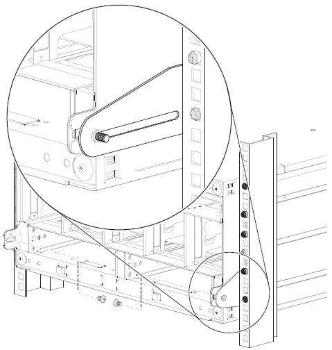
Facing the rear of the rack cabinet, remove the 2 Phillips-head M5 x 15 screws into the top and bottom holes of the rear mount bracket. Repeat for the rail.
-
Remove the Phillips-head M5 x 15 screw from front rack post, using an 8mm nut driver or a Philips screwdriver. Repeat for the other rail.
-
If necessary, loosen, but do not remove, all 4 rail slide set screws on each rail with a Philips screwdriver. Remove the rail from the rack. Repeat for the other rail.
-
Note: For detailed and illustrated instructions on installing Array Module rails in both round-hole and square-hole racks, see the Rail Kit Installation Instructions that are packaged with the rail kits.
Important Information
Use the flat-head M5 x 15 screws to mount the rails to the rack. Do not use the Panhead (rounded)10-32 screws with washers included in the rail kit to mount the rails to the rack. The Panhead 10-32 screws are used to attach the Array Module chassis to the rack (see DXi9200 Rack Mount Rails Replacement).
-
Remove both rail assemblies from their packaging.
-
Orient the rail with the LH FRONT embossed on it to your left, the other with the RH FRONT embossed on it to your right, and each emboss toward you, facing inward.
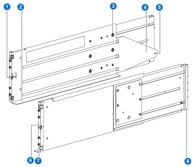
Item Description 1 Left front mount bracket 2 Left rail shelf 3 Rail slide set screw 4 Left rear tail 5 Rear mount 6 Right front mount bracket 7 Rack pin 8 Right rear mount bracket -
Loosen, but do not remove, all 4 rail slide set screws on each rail with a Philips screwdriver.
-
Select the left rail, then face the left side of the rack cabinet and slide the front mount bracket pins into the desired slots in the front rack post.
-
Insert a Phillips-head M5 x 15 screw through the rack post into the center of the front rack mount bracket and barely tighten against the front rack post, using an 8mm nut driver or a Philips screwdriver.
Note: Use the flat-head M5 x 15 screws to mount the rails to the rack. Do not use the Panhead (rounded) 10-32 screws with washers included in the rail kit to mount the rails to the rack.
-
Extend the length of the rail until the rear mount bracket pins in the mirror location on the rear rack post.
-
Verify that the rails are level at the same height on both rack posts, and that all location pins fully seat in the rack posts.
-
Facing the rear of the rack cabinet, insert 2 Phillips-head M5 x 15 screws into the top and bottom holes of the rear mount bracket.
Note: Use the flat-head M5 x 15 screws to mount the rails to the rack. Do not use the Panhead (rounded) 10-32 screws with washers included in the rail kit to mount the rails to the rack.
-
Hand tighten firmly against the rack post using an 8mm nut driver or a Philips screwdriver.
-
Facing the front of the rack cabinet, hand tighten both of the Phillips-head M5 x 15 screws using an 8mm nut driver or a Philips screwdriver so that the hex head flanges are flush with the front rack post.
-
Fix the adjusted length of the left rail by hand tightening all 4 rail slide set screws using a Phillips screwdriver.
-
Repeat the process for the right rail.
WARNING: The DXi9200 Array module each weigh 180 lbs (81.6 kg). Do not lift the storage enclosure without a mechanical lift.
-
Slide the plastic bag aside to allow access to the chassis.
WARNING: The box is deep, and the chassis is very heavy. Do not attempt to lift by yourself.
-
Locate three people to assist in moving the storage enclosure onto the mechanical lift, using an appropriate safe lifting technique to perform the following actions:
-
Position one person at the front to grip the front belt strap securely by both loops, not by any portion of the front or rear panel areas.
-
Position one person at each rear corner to grip both rear belt straps by the loops on that side.
-
Simultaneously lift the storage enclosure, using appropriate safe lifting technique while moving it to a static-protected location, and then to the mechanical lift for mounting to the rack cabinet.
-
-
Facing the front of the chassis, grasp the right rack flange cover, gently work the cover free, and set it aside in a safe location.
-
Grasp the left rack flange cover, gently work the cover free, and set it aside in a safe location.
-
Complete the following actions to position the mechanical lift and the 5U chassis:
-
Using proper safety precautions, position the 5U chassis on the mechanical lift perpendicular to the lift wheels.
-
Move the mechanical lift into position perpendicular to the rack cabinet so that the storage enclosure is parallel to the opening and is a minimum of 12.7cm to 17.8cm (5 to 7 inches)away from the rack cabinet.
-
Adjust the mechanical lift height to be as close as possible to the allocated 5U location.
-
Moving only the 5U chassis, position it so the chassis aligns with the outer rails in the rack.
-
-
Complete the following actions to properly secure the 5U chassis on its rails:
-
Keep the 5U chassis stationary on the mechanical lift.
-
Conduct a visual inspection of both sides to verify the bottom of the storage enclosure chassis rests squarely on the front of the bottom shelf of the outer rail and that the direction is straight in, not at an angle.
-
-
Complete the following actions to insert the 5U chassis into the rack cabinet:
-
Facing the front of the enclosure, carefully exert even pressure on both sides of the storage enclosure front, inserting the storage enclosure until the rack ear flanges are flush with the front rack posts.
-
Carefully lower the mechanical lift.
-
Thoroughly examine the rack rails for issues such as bowing, scraping, resistance, or indicators of misalignment.
-
-
Complete the following actions to secure the 5U chassis:
-
Remove and set aside the operator's (ops) panel.
-
Thread a lock washer and then a washer onto each of 2 Panhead 10-32 screws.
-
Facing the front of the enclosure, insert a Panhead 10-32 screw with washers into the top and bottom holes in the ops panel, then hand tighten firmly against front rack post with a Phillips screwdriver.
-
Slide the ops panel cover over the left rack ear flange until flush with the rack post.
-
Repeat the process for securing the right rack ear flange and replacing the right rack ear cover.
-
Facing the rear of the enclosure, insert and tighten an Panhead M5 x 8 screw through the chassis and into the tail of each outer rail with a Phillips screwdriver to secure the rear of the chassis.
-
-
Reconnect all power cables, Ethernet, and DAC cables on the RBOD.
Power on the DXi9200 system components in the following order:
-
Turn on both power switches on the back of the Array module (RBOD). Facing the front, observe the LEDs on the front panel area and confirm the Power On LED is in a steady green state.
Additional Information
- Check that all drives are correctly seated in all enclosures before powering on the node.
- After powering on the system, do not remove any hard drives. If you accidentally remove a drive, wait 30 seconds before reinserting the drive.
-
Press the power button on the front of the Node. Wait for the system to boot before continuing with the procedure. (This can take up to 10 minutes.)
Powering on the Array (RBOD) Modules
Powering on the Node