DXi9200 Power Supply Replacement
Overview
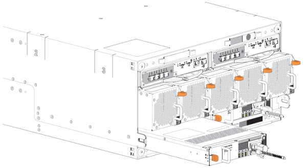
Follow the steps in this document to replace a failed power supply (PSU) in the DXi9200 Node and Array Module (RBOD).
DXi9200 uses redundant, hot-swappable power supplies. You do not need to shut down the system to remove and replace a power supply.
Take ESD Precautions
Some components within the DXi system contain static-sensitive parts. To avoid damaging these parts while performing installation procedures, always observe the following precautions:
- Keep static-sensitive parts in their original shipping containers until ready for installation.
- Do not place static-sensitive parts on a metal surface. Place them inside their protective shipping bag or on an anti-static mat.
- Wear anti-static wrist bands when unpacking and handling the units, and avoid touching connectors and other components.
- Dry climates and cold-weather heating environments have lower relative humidity and are more likely to produce static electricity.
DXi9200 Node Power Supply
Each DXi9200 Node power supply has an illuminated translucent handle that serves as an indicator to show whether power is present or whether a power fault has occurred:
| Not lit | Indicates power is not connected. |
| Green | Indicates a valid power source is connected to the power supply and that the power supply is operational. |
| Flashing amber | Indicates a problem with the power supply. |
| Flashing green | When hot-adding a power supply, this indicates that the power supply is mismatched with the other power supply. Replace the power supply that has the flashing indicator with a power supply that matches the capacity of the other installed power supply. |
All power supplies are hot swappable. When replacing power supplies, never remove more than one power supply at a time from the system. Also, before you remove one power supply, make sure the other power supply is operating correctly (indicator handle is green).
DXi9200 Node - Power Supply LED
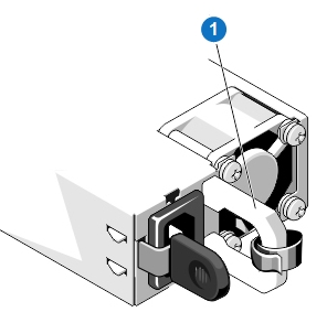
| 1 - Power supply status indicator and handle |
Note: This component is hot-swappable. You do not need to stop all I/O from clients or remove power to replace this component.
Required Tools: There are no tools required for this component replacement.
To replace a power supply unit (PSU):
-
Disconnect the power cable from the power outlet and from the PSU that you intend to remove.
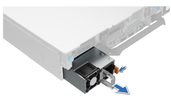
-
Press the release latch and holding the PSU handle, slide the PSU out of the bay.
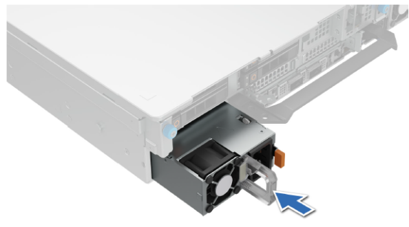
-
Slide the replacement PSU into the PSU bay until the release latch snaps into place.
-
Connect the power cable to the PSU, and plug the cable into a power outlet.
Wait for 15 seconds for the system to recognize the PSU and determine its status. The PSU redundancy may not occur until discovery is complete. The PSU status indicator turns green to indicate that the PSU is functioning properly.
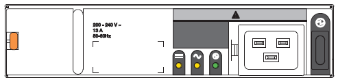
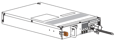
DXi9200 Array Module (RBOD) Power Supply
Each power supply unit (PSU) has three status LEDs. The asterisk (*) indicates a fault condition.
|
LED |
|
|

|
Status |
|---|---|---|---|---|
| Type | PSU fault | AC fault | PSU OK | N/A |
| Color | Amber | Amber | Green | |
| State | Off | AC power not present. | ||
| On | Off | PSU present, but not supplying power. | ||
| Flashing | Off | Firmware download to PSU in progress. | ||
| Off | On | AC power present, power switch is on, providing power. | ||
| Off | Flashing | AC power present, PSU on standby, other PSU providing power. | ||
| On | Communication with controller module (CM) lost. | |||
| On | N/A | Off | PSU hardware fault. | |
| On | Off | PSU alert state or hardware fault: over temperature, over voltage, or over current. | ||
| Off | On | Off | AC power failed, PSU not providing power, other PSU providing power. | |
| Off | On | AC power failed, PSU running on battery. | ||


Required Tools: There are no tools required for this component replacement.
Note: This component is hot-swappable. You do not need to stop all I/O from clients or remove power to replace this component.
The RBOD enclosure will maintain continuous operation during the replacement of a single PSU, if it is within the time limit of 7 minutes, since removal of a PSU significantly reduces airflow in the storage enclosure.
To replace a power supply unit (PSU):
-
Retrieve the new PSU in its static-protected container, ready to access and use the new PSU immediately upon removal of the faulty one.
-
Switch off the power for the faulty PSU.
-
Complete the following actions to remove the faulty PSU:
-
Release the PSU power cord from its secure tie, and then disconnect the power cord from the PSU connector.
-
Press the PSU release latch to the right to release the PSU from the midplane.
-
Use one hand to support the weight of the PSU and the other to pull the handle outward and withdraw the PSU.
-
Place it in a static-protected location.
-
-
Complete the following actions to install the replacement PSU:
-
Facing the rear of the storage enclosure, orient the new PSU with the latch to the left.
-
Use one hand to support the weight of the PSU and the other to guide it into the empty PSU slot.
-
Exerting even pressure to the center, gently press inward until it connects with the midplane and it locks in place.
-
Connect the power cord, then move the PSU power switch to the ON position.
-
-
Verify that the PSU OK LED is lit green on the replaced PSU after properly inserting and seating it in the empty slot.
-
Facing the front of the storage enclosure, verify that the Power On LED is green and there are no fault conditions.