minute read
DXi9200 Drive Replacement
Overview
Before you begin the drive replacement procedure, review the following information:
- You can perform this procedure only if there is a single failed drive in the DXi. If there are multiple drive failures, contact Quantum Support.
- Use only the Quantum-supplied replacement drive to perform the replacement procedure. Do not use any other drive (not even one taken from another DXi).
- The drives in the DXi are hot-swappable. Do not power down the DXi system to replace the failed drive.
- After the replacement drive is installed, the drive rebuilding process automatically begins and takes approximately three hours (Node drive) or seventeen hours (Array or Expansion module drive), depending on system load. You may use the DXi normally while the drive rebuilds, but system performance may be reduced.
Important Information
- Do not remove the failed drive completely from the DXi until instructed to do so. If you remove the failed drive but do not insert a replacement drive within a few minutes, the enclosure may overheat.
- Make sure to remove only the failed drive from the DXi. If you remove a drive that has not failed, multiple service tickets will occur. Re-insert the drive, and then contact Quantum Support.
Take ESD Precautions
Some components within the DXi system contain static-sensitive parts. To avoid damaging these parts while performing installation procedures, always observe the following precautions:
- Keep static-sensitive parts in their original shipping containers until ready for installation.
- Do not place static-sensitive parts on a metal surface. Place them inside their protective shipping bag or on an anti-static mat.
- Wear anti-static wrist bands when unpacking and handling the units, and avoid touching connectors and other components.
- Dry climates and cold-weather heating environments have lower relative humidity and are more likely to produce static electricity.
DXi9200 Node Disks
IMPORTANT INFORMATION
The DXi9200 contains a software RAID configuration. Disks in the software RAID MUST be removed from the software RAID before being physically removed and replaced with a new disk. Failure to remove the disk from the software RAID before removal will cause issues with adding a replacement disk to the software RAID.
The DXi9200 Node supports eight (110 TB - 1100 TB capacity) to sixteen (1155 TB to 2200 TB capacity) 1.92 TB NVMe solid state drives (SSDs). The Node hard drives are used for the operating system, system software, and indexes needed for data deduplication, replication, and space reclamation.
All solid state disk drives are mounted and pre-assembled in drive carriers.
DXi9200 Node Drive Slot Numbering
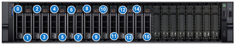
| 0 - SSD Slot 0 | 4 - SSD Slot 4 | 8 - SSD Slot 8 | 12 - SSD Slot 12 |
| 1 - SSD Slot 1 | 5 - SSD Slot 5 | 9 - SSD Slot 9 | 13 - SSD Slot 13 |
| 2 - SSD Slot 2 | 6 - SSD Slot 6 | 10 - SSD Slot 10 | 14 - SSD Slot 14 |
| 3 - SSD Slot 3 | 7 - SSD Slot 7 | 11 - SSD Slot 11 | 15 - SSD Slot 15 |
Locate the failed drive by observing the status LEDs on the front of each drive carrier in the DXi. You can remove the bezel from the Node if you have trouble viewing the LEDs
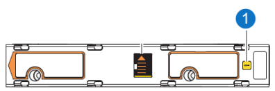
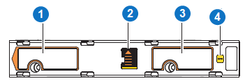
DXi9200 Node Drive Carrier LEDs
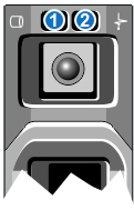
| 1 - Drive activity indicator (green) | 2 - Drive status indicator (green and amber) |
| LED Indicator | Activity |
|---|---|
| Drive activity indicator (green) |
|
| Drive status indicator (green and amber) |
|
Required Tools: There are no tools required for this component replacement.
Note: This component is hot-swappable. You do not need to stop all I/O from clients or remove power to replace this component.
-
Before removing the SSD drive, remove the drive from the software RAID. You can remove the disk using the Remote Management Console or CLI.
 Remove Disk - CLI
Command
syscli --remove disk --slot <number> [--sure]
Command Attributes
Review the following attribute descriptions.
‑‑remove diskRemoves a disk from the RAID set.
‑‑slot <number>Disk's slot number.
‑‑sureIf specified, the CLI executes the command without prompting for confirmation.
Remove Disk - Remote Management Console
Note: The remove disk feature is for external drives only.
To remove a disk:
-
To access the Hardware page, click the Utilities menu, and then click the Hardware tab.
-
Select the failed disk in the table to be removed from the RAID. The disk will have a status of Failed.
-
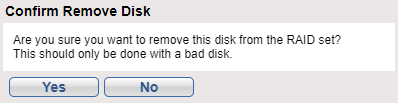
Click the Remove button. A dialog box appears asking if you want remove the disk from the RAID. Click Yes.
After removing a failed disk, the disk's status will no longer be available through the software RAID. Until the failed drive is physically removed from the system and replaced with a new drive, the failed disk status will appear as New in the NVMe Drive Replacement table.
-
-
Remove the node bezel to access the drives.
-
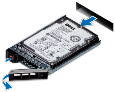
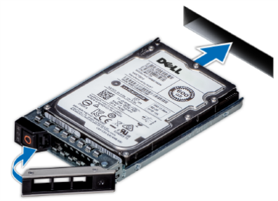
Press the release button to open the drive carrier release handle.
Note: Drives come pre-installed in drive carriers, so there is no need to remove the failed drive from its carrier when removing from the system
-
Holding the drive carrier release handle, slide the drive carrier out of the drive slot.
-
Slide the new drive carrier into the drive slot and push until the drive connects with the backplane.
-
Close the drive carrier release handle to lock the drive in place.
-
Reinstall the node bezel.
-
Add the replacement drive back into the software RAID. You can add the disk using the Remote Management Console or CLI.
Add Disk - CLI
Command
syscli --add disk --slot <number> [--sure]
Command Attributes
Review the following attribute descriptions.
‑‑add diskAdds a disk to a RAID.
‑‑slot <number>Disk's slot number.
‑‑sureIf specified, the CLI executes the command without prompting for confirmation.
Add Disk - Remote Management Console
The Add button will add a disk the software RAID that is not currently a part of the RAID. A disk that is not currently part of the software RAID will have a status of New.
To add a disk:
-
To access the Hardware page, click the Utilities menu, and then click the Hardware tab.
Select the disk in the table to be added to the RAID. The disk will have a status of New.
-
Click the Add button. A dialog box appears asking if you want to add the disk to the RAID. Click Yes.
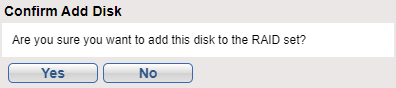
Once the disk has been added to the RAID, the drive will have a status of Healthy.
-
DXi9200 Array Module (RBOD) Disks
The DXi9200 Array modules (RBOD) each support 60 high capacity 20 TB NL-SAS hard disk drives (HDDs). The Array module hard drives are used for data storage.
All drives are mounted and pre-assembled in drive carriers.
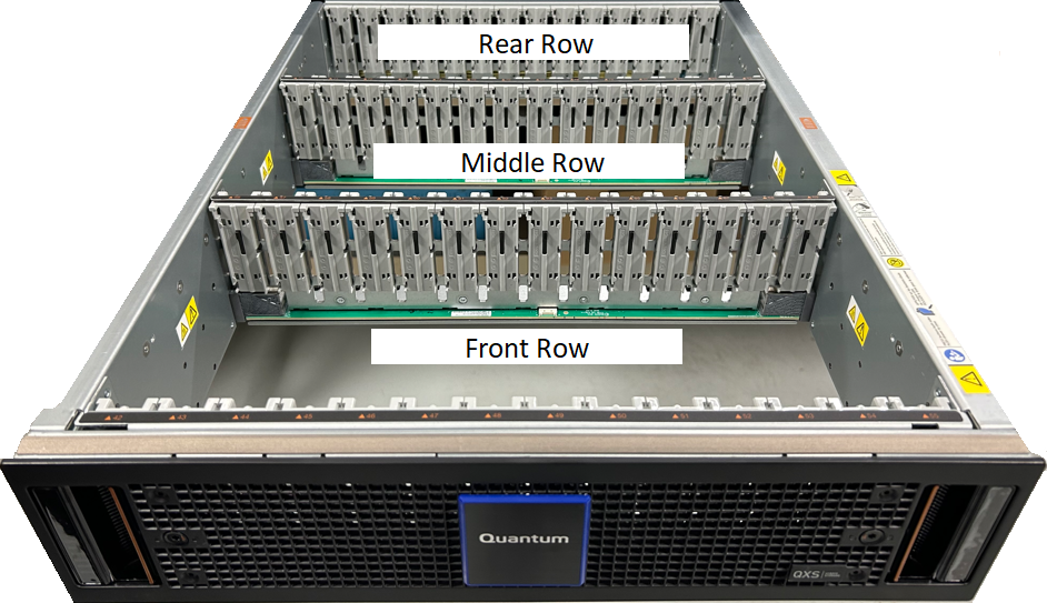
Array Module Drive Drawers
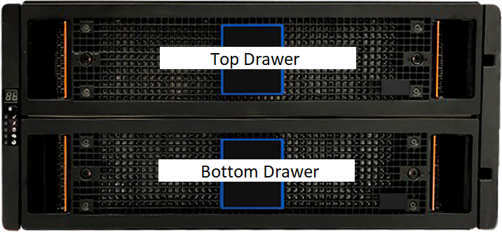
Each drawer has 3 rows: Front, Middle, and Rear.
The top drawer contains slots numbered from 0 to 41. The bottom drawer contains slots numbered from 42 to 83. At maximum drive configuration, the DXi9200 utilizes 70 drives per RBOD.
| Drawer | Row | Drive Slot Number (Left to Right) |
|---|---|---|
| Top | Front | 0 - 13 |
| Middle | 14 - 27 | |
| Rear | 28 - 41 | |
| Bottom | Front | 42 - 55 |
| Middle | 56 - 69 | |
| Rear | 70 - 83 |
Locate the failed drive by observing the status LEDs in the drive carrier.
DXi9200 Array Module Drive LEDs
The operator's (ops) panel registers either a logical fault or a drawer hardware fault or both. You must locate a faulty drive within the related drawer by its amber fault condition LED.
The DXi9200 Array drive module in its carrier uses a single amber fault LED to identify various states indicates a fault condition.
|
Item |
Indicator, Button, or Connector |
Color |
State | Status |
|---|---|---|---|---|
| 1 | LED indicator | Amber | On | Drive has hardware fault, replace as soon as possible. |
| Drive link down. | ||||
| Fast flash (1s on, 1s off) | Unit identification (UID) or locate is active for drive. | |||
| Slow flash (3s on, 1s off) | Drive in critical condition. | |||
| Failed array. | ||||
| Off | No AC power present. | |||
| Drive initialization in process. | ||||
| Drive quarantined. |
Required Tools: T20 Torx driver
Note: This component is hot-swappable. You do not need to stop all I/O from clients or remove power to replace this component.
Important Information
An important feature of the storage enclosure design is redundancy. The storage enclosure will maintain continuous operation during the replacement of a single disk, if it is within the time limit of 7 minutes, since opening a drawer to remove a drive significantly reduces airflow in the enclosure. Do not open the drawer until you are ready to replace the drive.
-
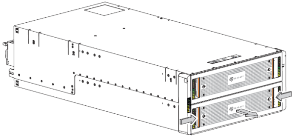
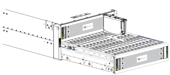
Do the following to open the related drawer:
-
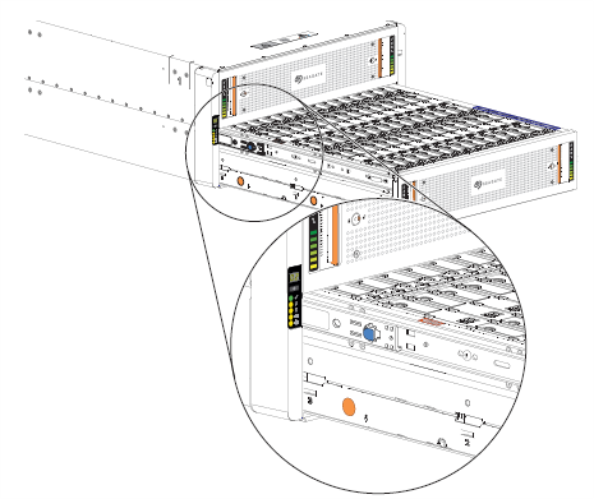
Facing the front of the storage enclosure, determine which drawer has a fault condition by the faut LEDs on the ops panel and drawer panels.
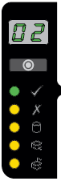
Op Panel
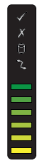
Drawer Panel
-
If the anti-tamper lock is engaged, use a T20 Torx driver to unlock both drawer pull handles.
-
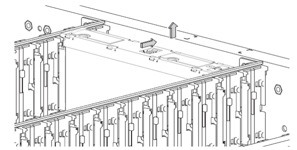
Simultaneously press both drawer latches inward and hold them there while exerting even outward pressure until all three rows are visible and the drawer slide latch locks in the open position.
-
Stop when the drawer rails engage the safety lock latches as the drawer reaches the open position, so that you can access all three rows of drives.
-
-
Complete the following actions to remove a faulty drive:
-
Locate the drive with a fault condition.
Item Description 1 Upper portion of carrier latch 2 Release latch, release latch arrow, open state 3 Lower portion of carrier latch 4 Fault condition LED -
Using a thumb, press the release latch arrow to the right to release the drive from its seated position.
-
Grasping the top of the drive carrier, pull it upwards until it clears its drawer slot.
-
Place it in a static-protected location.
-
-
Complete the following actions to insert the new replacement drive:
-
Orient the new drive so the LED is towards the drawer front, and the release latch arrow towards the rear.
-
Align the drive carrier with the empty drawer slot, then lower it fully into the slot.
-
Push the new drive down until the top is flush with the top of the slot.
-
While holding it against the bottom of the slot, slide the top latch toward the rear of the drawer until it locks into place and the drive release latch locks.

Release latch open and unlocked 
Release latch properly locked -
Verify that all drives are at the same level and all drive release latches are properly locked.
Caution: Do not proceed to close the drawer unless all drives are in a fully locked position or drive height can inhibit or completely prevent drawer access once you close it.
-
Confirm that the drive fault condition LED is off.
-
-
Complete the following actions to close the related drawer:
-
Press and hold the safety lock latches with the blue touchpoint at the front of both extended drawer slide rails.
-
Pressing simultaneously inward, begin sliding the drawer back into place until the safety lock clears the opening.
-
Placing the heels of both palms against the face of the drawer near the anti-tamper locks, exert even inward pressure until the drawer is almost flush with the rack ear flanges.
-
Simultaneously press inward and hold both drawer pull handles as you push the drawer closed until it fully latches.
-
-
Verify that the fault LED on the replaced drive is off after properly inserting and seating it in the empty slot.
-
Facing the front of the storage enclosure, verify that the Power On LED is green and there are no fault conditions.