minute read
DXi9200 RBOD Controller Module Replacement
Overview
Each DXi9200 Array (RBOD) Module contains two Controller Modules. These modules manage the flow of data to and from the RBOD.
Take ESD Precautions
Some components within the DXi system contain static-sensitive parts. To avoid damaging these parts while performing installation procedures, always observe the following precautions:
- Keep static-sensitive parts in their original shipping containers until ready for installation.
- Do not place static-sensitive parts on a metal surface. Place them inside their protective shipping bag or on an anti-static mat.
- Wear anti-static wrist bands when unpacking and handling the units, and avoid touching connectors and other components.
- Dry climates and cold-weather heating environments have lower relative humidity and are more likely to produce static electricity.
Locate the failed controller module by observing the status LEDs on the module:
DXi Array Module – Control Module
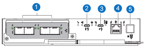
| Item | Indicator, Button, or Connector | Description |
|---|---|---|
| 1 | SCSI ports | SCSI ports data exchange with DXi9200 Node. |
| 2 | USB port | Manufacturing Universal Serial Bus (USB) port: do not use |
| 3 | USB port | CLI port: do not use. |
| 4 | Ethernet port | Ethernet connection to DXi Node. |
| 5 | SAS expansion port | SAS expansion 12Gb/s data exchange with other expansion enclosures. |
DXi Array Module – Control Module Fault LEDs
|
LED |
Type |
Color |
State | Status |
|---|---|---|---|---|

|
SCSI port | Amber | On | Critical cable fault. |
| Fast flash* (1s on, 1s off) | Unit identification (UID) active. | |||
| Slow flash* (3s on, 1s off) | Non-critical cable fault. | |||
| Off | Port functioning properly. | |||

|
Hardware fault | Amber | On | CM hardware fault. |
| Fast flash (1s on, 1s off) | Part of sequence as CM comes online. | |||
| Off | CM functioning properly. | |||

|
OK to remove | White | On | Ready for removal, the cache is clear. |
| Off | Do not remove the CM, cache still contains unwritten data. |
Replacement Procedure
Required Tools: There are no tools required for this component replacement.
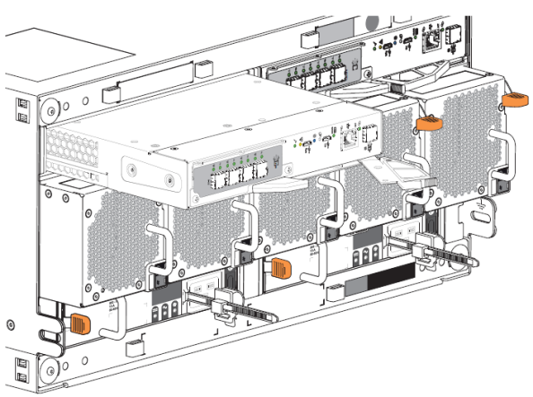
To replace an Array Module (RBOD) Controller Module:
-
Facing the rear of the storage enclosure, carefully remove all CM connections.
-
Grasp the Controller Module release latch between thumb and forefinger, then squeeze together to release the latch and handle.
-
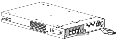
Pull the handle outward to lever the Controller Module away from the midplane.
-
Use one hand to support the weight of the Controller Module and the other to gently withdraw the module from its slot.
-
Place the Controller Module in a static-protected location.
-
Facing the rear of the storage enclosure, orient the replacement Controller Module with the open latch identically to the module you removed.
-
Use one hand to support the weight of the Controller Module and the other to guide it into the empty module slot.
-
Exerting even pressure to the center, gently press it against the midplane until the latch closes and locks in place
-
Reconnect all cables as they were connected before.
-
Verify that the Hardware Normal LED is lit green on the replacement Controller Module after properly inserting and seating it in the empty slot
-
Facing the front of the storage enclosure, verify that the Power On LED is green and there are no fault conditions.