minute read
DXi9200 RBOD Chassis Replacement
Overview
The DXi9200 Array modules (RBODs) are used to provide additional capacity (backup data storage) for the DXi9200 system. The DXi9200 includes 1 or 2 RBODs.
Make sure the following conditions are met before you continue with the chassis replacement:
- All backup jobs are completed and there is no pending I/O.
- All replication jobs are completed, and replication is paused (Replication > Actions page).
- All space reclamation tasks are completed without errors (Utilities > Space Reclamation page).
- All healthchecks are completed without errors (Utilities > Space Reclamation page).
- All components in the system display Normal status (Status > Hardware page).
- All outstanding administration alerts are deleted (Alerts > Admin Alerts page).
- All service tickets are closed (Alerts > Service Tickets page).
Note: For more information, click Help in the remote management console to display the DXi online help.
To access the remote management console, do the following:
-
Launch a supported Web browser on a workstation that has network access to the DXi9200.
The DXi GUI is compatible with Chromium-based web browsers. Quantum-tested Chromium-based browsers include Brave, Google Chrome, Microsoft Edge, Opera and Vivaldi. Mozilla Firefox is also compatible with the GUI.
-
In the browser address box, type the IP address of the DXi9200, and then press Enter.
The Login window displays.
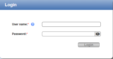
If the Login window does not display, verify that the IP address is correct and that the network path to the DXi9200 is valid. Also verify that you are using a supported Web browser. Then try again. If you are still unable to access the Login window, contact the DXi GUI administrator.
-
Select the Service login type and enter the corresponding password.
Note: Contact the DXi system GUI Administrator for the Service password.
- Click Login.
-
If a security banner message has been specified for the DXi9200, click Accept.
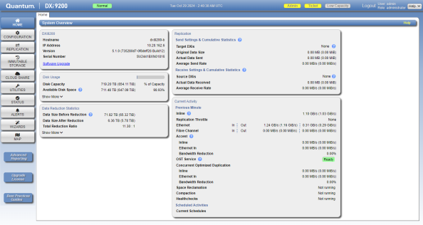
The Home page displays.
The following tools are required for replacing the chassis.
- #2 Phillips screwdriver
- Small flat head screwdriver
- Mechanical lift
Some components within the DXi9200 system contain static-sensitive parts. To avoid damaging these parts while performing installation procedures, always observe the following precautions:
- Keep the DXi9200 system turned off during all installation procedures.
- Keep static-sensitive parts in their original shipping containers until ready for installation.
- Do not place static-sensitive parts on a metal surface. Place them inside their protective shipping bag or on an antistatic mat.
- Wear anti-static wrist bands when unpacking and handling the units, and avoid touching connectors and other components.
Note: Dry climates and cold-weather heating environments have lower relative humidity and are more likely to produce static electricity.
Replacement Procedure
Note: Download the system logs from the Utilities > Diagnostics > System Diag File page before shutting down. This will provide a record of the system prior to any hardware configuration changes.
-
Shut down the system from the remote management console using the Shutdown option on the Utilities > Reboot & Shutdown page.
Note: Shutting down the system can take up to 15 minutes. Only the Node will completely shut down.
-
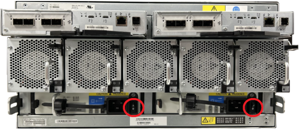
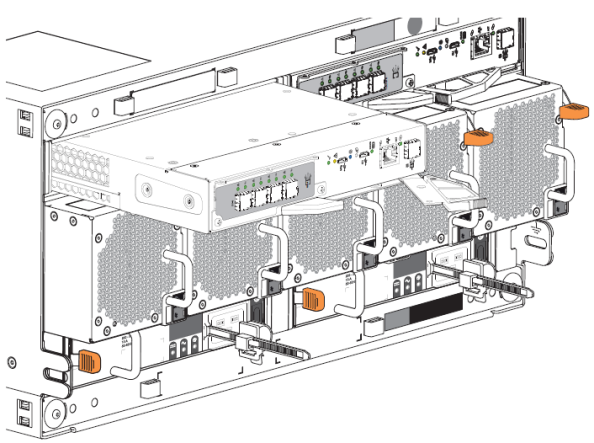
After the Node shuts down, remove power from the Array module(s). Press the power switch to the OFF position for each PSU.
Caution: Never remove power from a redundant power supply unit (PSU) when the other PSU has a fault condition, indicated by an amber LED.
Array Module (RBOD) Power Switches
-
Disconnect each power connector from its PSU socket or from the PDU.
Note: You must wait a minimum of 15 seconds before power cycling the PSU and a minimum of 30 seconds after successful completion of the power on sequence before you attempt to place the PSU in standby or remove power again.
Remove all power cables, Ethernet, and DAC cables from the rear of the Array Module. Make sure to label the cables so they can be easily identified when they are re-connected to the module after the replacement procedure is complete.
Remove the following parts from the chassis. These will be installed in the replacement chassis.
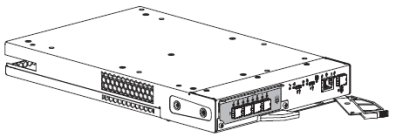
-
Grasp the Controller Module release latch between thumb and forefinger, then squeeze together to release the latch and handle.
-
Pull the handle outward to lever the Controller Module away from the midplane.
-
Use one hand to support the weight of the Controller Module and the other to gently withdraw the module from its slot.
-
Place the Controller Module in a static-protected location.
-
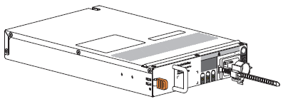
Complete the following actions to remove the PSU:
-
Press the PSU release latch to the right to release the PSU from the midplane.
-
Use one hand to support the weight of the PSU and the other to pull the handle outward and withdraw the PSU.
-
Place it in a static-protected location.
-
-
Complete the following actions to remove the cooling module:
-
Facing the rear of the rack cabinet, press downward to release the cooling module latch.
-
Use one hand to support the cooling module weight and the other to gently withdraw the cooling module all the way from its slot.
-
Place it in a static-protected location.
-
-
Complete the following actions to remove a drive:
-
Using a thumb, press the release latch arrow to the right to release the drive from its seated position.
-
Grasping the top of the drive carrier, pull it upwards until it clears its drawer slot.
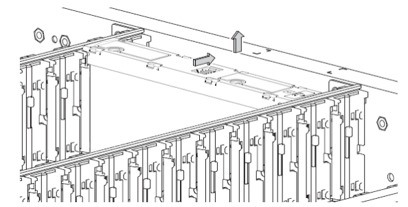
-
Place it in a static-protected location.
-
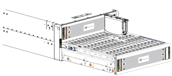
WARNING: The DXi9200 Array module each weigh 180 lbs (81.6 kg) empty. Do not lift the storage enclosure without a mechanical lift.
-
Complete the following actions on the 5U chassis:
-
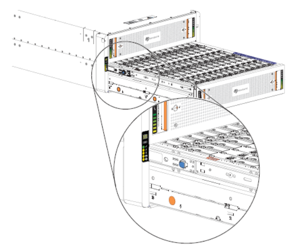
Remove and set aside the operator's (ops) panel.
-
Facing the front of the enclosure, remove the Panhead 10-32 screw with washers into the top and bottom holes in the ops panel.
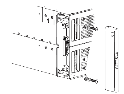
-
Repeat the process for removing the right rack ear flange and removing the right rack ear cover.
-
Facing the rear of the enclosure, remove the Panhead M5 x 8 screw through the chassis and into the tail of each outer rail with a Phillips screwdriver.
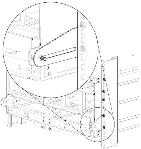
-
-
Complete the following actions to position the mechanical lift next to the 5U chassis:
-
Move the mechanical lift into position perpendicular to the rack cabinet so that the storage enclosure is parallel to the opening and is a minimum of 12.7cm to 17.8cm (5 to 7 inches)away from the rack cabinet.
-
Adjust the mechanical lift height to be as close as possible to the allocated 5U location
-
Facing the rear of the chassis, carefully exert even pressure on both sides of the chassis rear, slide the chassis on to the mechanical lift.
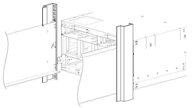
-
Carefully lower the mechanical lift.
-
Install the following parts from the previous chassis into the replacement chassis.
-
Facing the rear of the storage enclosure, orient the Controller Module with the open latch identically to the module you removed.
-
Use one hand to support the weight of the Controller Module and the other to guide it into the empty module slot.
-
Exerting even pressure to the center, gently press it against the midplane until the latch closes and locks in place
-
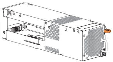
Complete the following actions to install the PSU:
-
Facing the rear of the storage enclosure, orient the new PSU with the latch to the left.
-
Use one hand to support the weight of the PSU and the other to guide it into the empty PSU slot.
-
Exerting even pressure to the center, gently press inward until it connects with the midplane and it locks in place.
-
Connect the power cord, then move the PSU power switch to the ON position.
-
-
Complete the following actions to install the cooling module:
-
Orient the new cooling module with the latch to the right.
-
Use one hand to support the weight of the cooling module and the other to guide it into the empty cooling module slot.
-
Exerting even pressure to the center, gently press inward until it connects with the midplane and it locks in place.
-
-
Complete the following actions to insert the drive:
-
Orient the new drive so the LED is towards the drawer front, and the release latch arrow towards the rear.
-
Align the drive carrier with the empty drawer slot, then lower it fully into the slot.
-
Push the new drive down until the top is flush with the top of the slot.
-
While holding it against the bottom of the slot, slide the top latch toward the rear of the drawer until it locks into place and the drive release latch locks.

Release latch open and unlocked 
Release latch properly locked -
Verify that all drives are at the same level and all drive release latches are properly locked.
Caution: Do not proceed to close the drawer unless all drives are in a fully locked position or drive height can inhibit or completely prevent drawer access once you close it.
-
-
Complete the following actions to close the related drawer:
-
Press and hold the safety lock latches with the blue touchpoint at the front of both extended drawer slide rails.
-
Pressing simultaneously inward, begin sliding the drawer back into place until the safety lock clears the opening.
-
Placing the heels of both palms against the face of the drawer near the anti-tamper locks, exert even inward pressure until the drawer is almost flush with the rack ear flanges.
-
Simultaneously press inward and hold both drawer pull handles as you push the drawer closed until it fully latches.
-
Reconnect all power cables, Ethernet, and DAC cables on the RBOD.
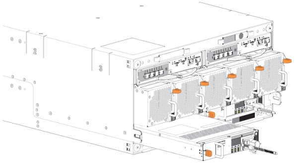
Power on the DXi9200 system components in the following order:
-
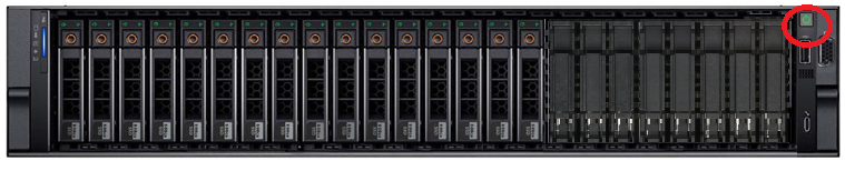
Turn on both power switches on the back of the Array module (RBOD). Facing the front, observe the LEDs on the front panel area and confirm the Power On LED is in a steady green state.
Additional Information
- Check that all drives are correctly seated in all enclosures before powering on the node.
- After powering on the system, do not remove any hard drives. If you accidentally remove a drive, wait 30 seconds before reinserting the drive.
-
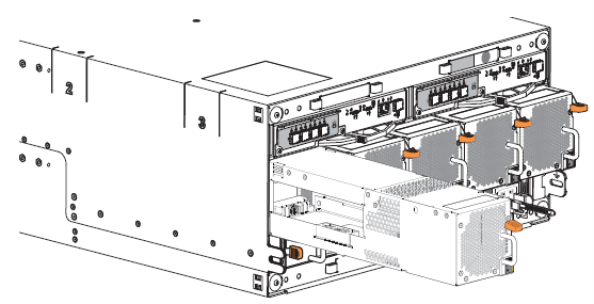
Press the power button on the front of the Node. Wait for the system to boot before continuing with the procedure. (This can take up to 10 minutes.)
Powering on the Array (RBOD) Modules
Powering on the Node