minute read
DXi9000 Series Node Front Panel Features and Indicators
The controls, indicators, and connectors are located behind the optional rack bezel on the front panel of the DXi9000 Series Node.
DXi9000 Series Node - Front View
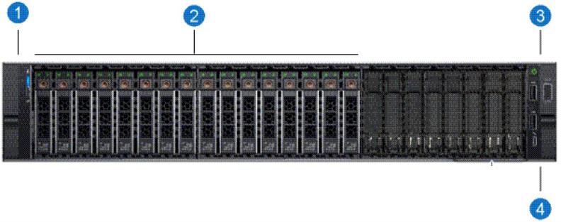
DXi9000 Series Node - Front Panel LED Indicators, Buttons, and Connectors
| Item | Indicator, Button, or Connector | Description |
|---|---|---|
| 1 | Left control panel |
Contains system health and system ID, and status LEDs. See DXi9000 Series Node - Left Control Panel for more information. Note: The diagnostic indicators display error statuses during system startup. |
| 2 | Solid state drives (SSDs) | Five or sixteen 2.5 inch hot-swappable solid state drives (960 GB each). |
| 3 | Right control panel | Contains the power button, VGA port, iDRAC Direct micro USB port and two USB 2.0 ports. See DXi9000 Series Node - Right Control Panel for more information. |
| 4 | Information tag | A slide-out label panel which displays the system serial number. |
DXi9000 Series Node - Left Control Panel
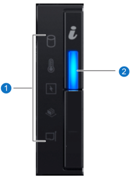
DXi9000 Series Node - Left Control Panel Indicators
| Item | Indicator, Button, or Connector | Description |
|---|---|---|
| 1 | Status LED Indications |
The diagnostic indicators light up to display error statuses. For a description of possible statuses, see the table below. Note: The diagnostic indicators display error statuses during system startup. |
| 2 | System Health and System ID Indication |
Indicates the system health. Solid blue - The system is on and in good health. Blinking amber - The system is on and an error exists. If an error exists, see General Troubleshooting . |
DXi9000 Series Node - Status LED Indicators
|
Indicator |
Icon |
Condition |
Recommended Action |
| Hard Drive |
|
Blinking amber - A hard drive error has occurred | See Hardware Problems. |
| Temperature |
|
Blinking amber - A thermal error has occurred. | See Temperature Problems. |
| Electrical |
|
Blinking amber - An electrical error has occurred. | See Hardware Problems |
| Memory |
|
Blinking amber - A memory error has occurred. | See General Troubleshooting . |
| PCIe |
|
Blinking amber - A PCIe card error has occurred. | See General Troubleshooting . |
DXi9000 Series Node - Right Control Panel
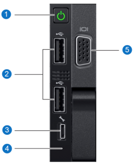
DXi9000 Series Node - Right Control Panel Indicators
| Item | Indicator, Button, or Connector | Description |
|---|---|---|
| 1 | Power-on indicator, power button |
The power-on indicator lights when the system power is on. The power button controls the power supply output to the system. WARNING: Turning off the power removes the main power but keeps standby power supplied to the Node. Because of this, you must unplug the Node before servicing. Caution: Turning off the power without properly shutting down the system may result in loss of data. Note: To shut down the Node in the event of an emergency, press and hold the power button for 4 seconds. Warning: This may result in data loss and may cause a delay on next startup due to a blockpool verify operation. |
| 2 | USB 2.0 connectors |
Caution: Use of connected peripheral devices, such as a USB keyboard and mouse or a VGA display, is not supported and may cause incorrect system operation. |
| 3 | iDRAC port | For Quantum service use only. |
| 4 | iDRAC LED | For Quantum service use only. |
| 5 | VGA port |
Caution: Use of connected peripheral devices, such as a USB keyboard and mouse or a VGA display, is not supported and may cause incorrect system operation. |
| Item | Indicator, Button, or Connector | Description |
|---|---|---|
| 1 | Power-on indicator, power button |
The power-on indicator lights when the system power is on. The power button controls the power supply output to the system. WARNING: Turning off the power removes the main power but keeps standby power supplied to the Node. Because of this, you must unplug the Node before servicing. Caution: Turning off the power without properly shutting down the system may result in loss of data. Note: To shut down the Node in the event of an emergency, press and hold the power button for 4 seconds. Warning: This may result in data loss and may cause a delay on next startup due to a blockpool verify operation. |
| 2 | USB 2.0 connector |
Caution: Use of connected peripheral devices, such as a USB keyboard and mouse or a VGA display, is not supported and may cause incorrect system operation. |
| 3 | iDRAC port | For Quantum service use only. |
| 4 | VGA port |
Caution: Use of connected peripheral devices, such as a USB keyboard and mouse or a VGA display, is not supported and may cause incorrect system operation. |