minute read
DXi9000 Series Rack Mount Rails Replacement
Overview
Follow the steps in this document to replace the rack mount rails in the DXi9000 Series.
Necessary Tools
Before you begin, gather the necessary tools:
- Small flat head screwdriver
- Large flat head screwdriver
- #2 Phillips screwdriver
Caution: Use appropriate ESD precautions, including the use of a grounding strap, when performing any of these procedures.
To remove the DXi9000 Series Node from the rack:
- Shut down the DXi9000 Series system (see DXi9000 Series Rack Mount Rails Replacement).
- If installed, remove the front bezel from the Node by lifting the latch on the left side of the bezel.
- Remove all power, SAS, Ethernet, and Fibre Channel cables from the rear of the Node. Make sure to label the cables so they can be easily identified when they are re-connected to the Node after the replacement procedure is complete.
-
Press the locking tab on either side of the Node, and slide the Node out from the rack until the inner rails lock.
Caution: Do not use excessive force when pulling the chassis forward to fully extend the Node or Expansion Module in the rack rails. Using excessive force could bypass the slide rail stop mechanism.
Note: If necessary, remove the optional screws securing the Node to the front of the rack (behind the locking tab).
-
Locate the lock levers on the sides of the inner rails. Unlock each lever by rotating it up to its release position.

- Grasp the sides of the Node firmly and pull it forward until the rail standoffs are at the front of the J-slots.
-
Lift the Node up and away from the rack and place it on a level surface.
WARNING: The DXi9000 Series Node (including hard drives) weighs 62.0 pounds (28.1 kg). A minimum of two people are required to lift the chassis.
-
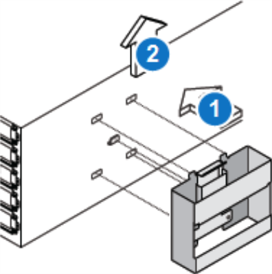
Use a flat head screwdriver to lift the latch release button on the end piece midpoint and unseat each rail, and then remove the rails from the rack.
To install the replacement DXi9000 Series Node rack mounting rails:
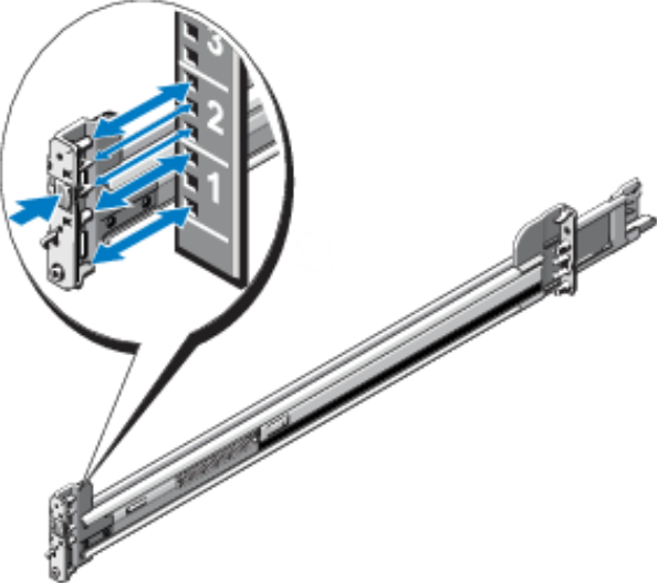
- Position the left and right rail end pieces labeled FRONT facing inward, and orient each end piece to seat in the holes on the front side of the vertical rack flanges.
- Align each back end piece in the bottom and top holes of the desired U spaces.
- Engage the back end of the rail until it fully seats on the vertical rack flange and the latch clicks into place. Repeat these actions to position and seat the front end piece on the vertical rack flange.

To install the DXi9000 Series Node:
-
Pull the inner slide rails out of the rack until they lock into place.
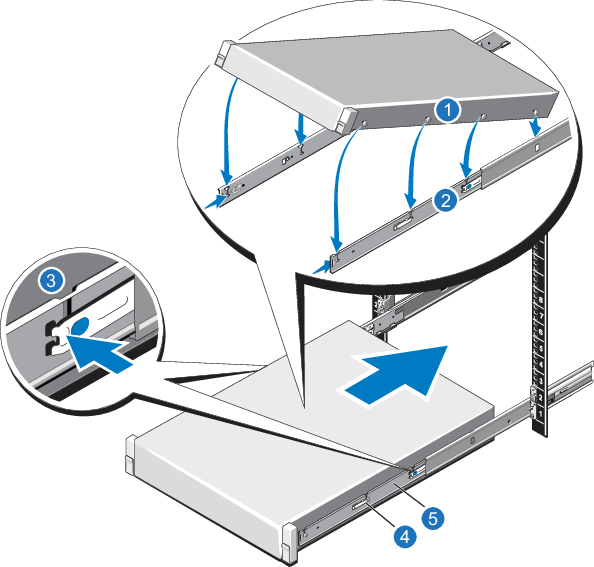
- Locate the rear rail standoff on each side of the system and lower them into the rear J-slots on the slide assemblies.
- Rotate the system downward until all the rail standoffs are seated in the J-slots.
- Push the system inward until the lock levers click into place.
- Press the slide-release lock buttons on both rails and slide the system into the rack.
- Reconnect all power, SAS, Ethernet, and Fibre Channel cables on the rear of the Node.
- Turn on the system (see Turn On the System).
- If applicable, replace the front bezel. Insert the right side of the bezel into the slots on the right side of the Node, then snap the left side of the bezel into place.
- Shut down the DXi9000 Series system (see DXi9000 Series Rack Mount Rails Replacement).
- Remove all power and SAS cables from the rear of the Array or Expansion Module. Make sure to label the cables so they can be easily identified when they are re-connected to the module after the replacement procedure is complete.
- Remove the end caps from each side of the Array or Expansion Module.
- Use a 10-32 x 3/4 in. SEM screw with washer at the bottom hole on each side of the Array or Expansion module’s front panel to secure the module to the rack.
- Slide the Array or Expansion Module out of the rack and place it on a level surface.
- Pull on the blue release latch on each end piece and unseat the rail from the rack.
WARNING: The DXi9000 Series Array Module (RBOD) and Expansion Module (EBOD) weigh 55.6 pounds (25.2 kg) and 54.7 pounds (24.8 kg) respectively. A minimum of two people are required to lift either chassis.
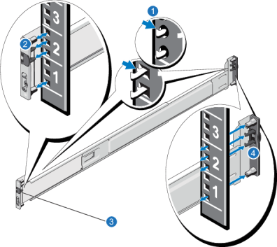
| Item | Description |
|---|---|
| 1 | Latches click into place in rack flange (round or square holes). |
| 2 | Rail front end. |
| 3 | Latch release button. |
| 4 | Rail back end. |
To install the replacement DXi9000 SD Array Module or Expansion Module rack mounting rails
- Position the left and right rail end pieces labeled FRONT facing inward, and orient each end piece to seat in the holes on the front side of the vertical rack flanges.
- Align each back end piece in the bottom and top holes of the desired U spaces.
- Engage the back end of the rail until it fully seats on the vertical rack flange and the latch clicks into place. Repeat these actions to position and seat the front end piece on the vertical rack flange.
| Item | Description |
|---|---|
| 1 | Latches click into place in rack flange (round or square holes). |
| 2 | Rail front end. |
| 3 | Latch release button. |
| 4 | Rail back end. |
WARNING: The DXi9000 Series Array module and Expansion module (including hard drives) weigh 63.9 pounds (29.0 kg) and 59.8 lb (27.1 kg) respectively. A minimum of two people are required to lift the chassis.
Caution: Before proceeding, ensure that all hard drive latches are completely closed. Quantum recommends that you do not remove the hard drives from the chassis. If they have been removed for any reason during or after the installation, you must install the hard drives in the same position in which they were removed.
- Align the Array or Expansion module with the rails, and then slide the module into the rack.
- Use a 10-32 x 3/4 in. SEM screw with washer at the bottom hole on each side of the Array or Expansion module’s front panel to secure the module to the rack.
-
Install the end caps on either side of the module by inserting the top of the end cap first and then snapping the bottom into place.
Install the end cap with the indicator icons to the left of the module, and install the end cap with the drive numbers to the right of the module.

Item Description 1 10-32 x 3/4 in. screw and nylon washer 2 Front of Array or Expansion Module - Reconnect all power, SAS, Ethernet, and Fibre Channel cables on the rear of the Node.
- Turn on the system (see Turn On the System).
WARNING: An empty DXi9000 HD Array module and Expansion module weigh 132.0 pounds (60.0 kg). A DXi9000 HD Array module and Expansion module containing 60 drives weigh 250 pounds (113 kg). A mechanized lift is recommended for removal.
To remove the DXi9000 HD Array or Expansion Module from the rack:
- Shut down the DXi9000 HD system (see DXi9000 Series Rack Mount Rails Replacement).
- Remove all power and SAS cables from the rear of the Array or Expansion Module. Make sure to label the cables so they can be easily identified when they are re-connected to the module after the replacement procedure is complete.
-
Remove the screws and PEM nuts securing the module to the front of the rack.
Module Screws in the Rack

-
If you are using a mechanized lift to remove the module, you do not need the module handles. If you are lifting and moving the module by hand, slide the module out of the rack until you can attach the two front handles. Push up on each handle until it clicks into place
Module Handles
-
Supporting the module from the bottom, slide it out of the cabinet until you can attach the two rear handles. Remove the module from the cabinet.
To install the Array or Expansion Module Rack Mounting Rails
- Position the left and right rail end pieces labeled FRONT facing inward, and orient each end piece to seat in the holes on the front side of the vertical rack flanges.
- Align each back end piece in the bottom and top holes of the desired U spaces.
- Engage the back end of the rail until it fully seats on the vertical rack flange and the latch clicks into place. Repeat these actions to position and seat the front end piece on the vertical rack flange.
- Using the screws provided, bolt the rails to the rack on both the front and back.
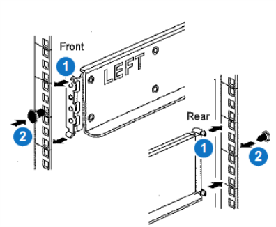
| Item | Description |
|---|---|
| 1 | Latches click into place in rack flange (round or square holes). |
| 2 | Screws |
WARNING: The DXi9000/DXi9100 HD Array module and Expansion module (empty) each weigh 132.0 pounds (60.0 kg). A minimum of two people are required to lift the chassis.
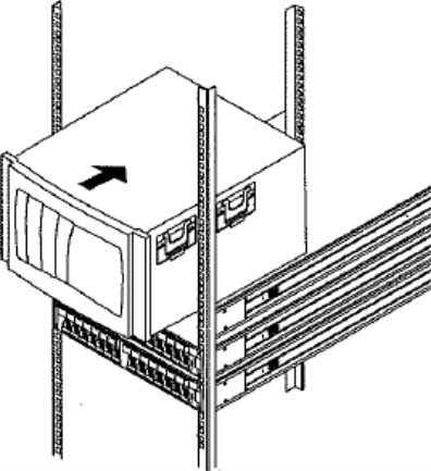
To install the Array Module or Expansion Module:
-
If you are using a mechanized lift, you do not need the module handles. If you are lifting and moving the module by hand, attach the four handles. Push up on each handle until it clicks into place.
- Place the back of the module (the end with the connectors) on the rails.
-
Supporting the module from the bottom, slide it into the cabinet. If you are using the handles, use the thumb latches to detach the handles as you slide the module in.
-
Using the provided screws and PEM nuts, secure the module to the front of the rack by inserting two screws in the 1st and 3rd holes (counting down from the top) on each side.
Secure Module to the Rack
- Reconnect all power, SAS, Ethernet, and Fibre Channel cables on the rear of the Node.
- Turn on the system (see Turn On the System).
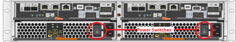
Power on the DXi9000 Series system components in the following order:
-
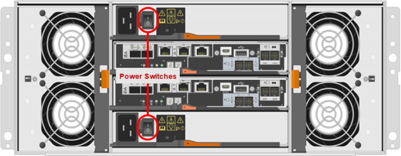
Turn on both power switches on the back of each Expansion module (EBOD). Wait until the seven segment displays on the rear of EBOD.
For DXi9000 SD systems, the seven segment display will display the number of EBODs connected to the system, starting with 00 for the first EBOD, 01 for the second EBOD, up to 08 for the ninth EBOD.
For DXi9000 HD systems, the seven segment display will display 00.
-
Turn on both power switches on the back of each Array module (RBOD). Wait until the seven segment display on the rear of the module displays 99 (approximately 5 minutes).
Additional Information
- Check that all drives are correctly seated in all enclosures before powering on the node.
- After powering on the system, do not remove any hard drives. If you accidentally remove a drive, wait 30 seconds before reinserting the drive.
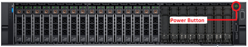
-
Press the power button on the front of the Node. Wait for the system to boot before continuing with the procedure. (This can take up to 10 minutes.)
Powering on the DXi9000 SD Expansion Modules

Powering on the DXi9000 HD Expansion Modules

Powering on the DXi9000 SD Array Modules
Powering on the DXi9000 HD Array Modules
Powering on the Node