minute read
DXi9000 Series Drive Replacement
Overview
Before you begin the drive replacement procedure, review the following information:
- You can perform this procedure only if there is a single failed drive in the DXi. If there are multiple drive failures, contact Quantum Support.
- Use only the Quantum-supplied replacement drive to perform the replacement procedure. Do not use any other drive (not even one taken from another DXi).
- The drives in the DXi are hot-swappable. Do not power down the DXi system to replace the failed drive.
- Installing the replacement drive will take approximately 30 minutes.
- After the replacement drive is installed, the drive rebuilding process automatically begins and takes approximately three hours (Node drive) or seventeen hours (Array or Expansion module drive), depending on system load. You may use the DXi normally while the drive rebuilds, but system performance may be reduced.
Important Information
- Do not remove the failed drive completely from the DXi until instructed to do so. If you remove the failed drive but do not insert a replacement drive within a few minutes, the enclosure may overheat.
- Make sure to remove only the failed drive from the DXi. If you remove a drive that has not failed, multiple service tickets will occur. Re-insert the drive, and then contact Quantum Support.
Take ESD Precautions
Some components within the DXi system contain static-sensitive parts. To avoid damaging these parts while performing installation procedures, always observe the following precautions:
- Keep static-sensitive parts in their original shipping containers until ready for installation.
- Do not place static-sensitive parts on a metal surface. Place them inside their protective shipping bag or on an anti-static mat.
- Wear anti-static wrist bands when unpacking and handling the units, and avoid touching connectors and other components.
- Dry climates and cold-weather heating environments have lower relative humidity and are more likely to produce static electricity.
The DXi9000 Series Node supports sixteen high capacity solid state drives (SDDs).
Note: The DXi9100 arrives with 13 drives installed in slots 0-12.
DXi9000 Node Drive Slot Numbering
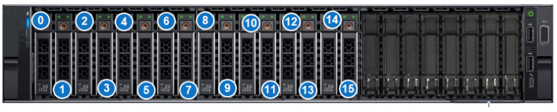
| 0 - SSD Slot 0 | 4 - SSD Slot 4 | 8 - SSD Slot 8 | 12 - SSD Slot 12 |
| 1 - SSD Slot 1 | 5 - SSD Slot 5 | 9 - SSD Slot 9 | 13 - SSD Slot 13 |
| 2 - SSD Slot 2 | 6 - SSD Slot 6 | 10 - SSD Slot 10 | 14 - SSD Slot 14 |
| 3 - SSD Slot 3 | 7 - SSD Slot 7 | 11 - SSD Slot 11 |
The DXi9000 SD Array modules (RBODs) and Expansion modules (EBODs) each support twelve high capacity 12 TB hard disk drives (HDDs).
DXi9000 SD Array and Expansion Module Drive Slot Numbering
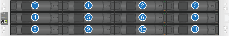
| 1 - HDD Slot 1 | 4 - HDD Slot 2 | 7 - HDD Slot 3 | 10 - HDD Slot 4 |
| 2 - HDD Slot 5 | 5 - HDD Slot 6 | 8 - HDD Slot 7 | 11 - HDD Slot 8 |
| 3 - HDD Slot 9 | 6 - HDD Slot 10 | 9 - HDD Slot 11 | 12 - HDD Slot 12 |
The DXi9000/DXi9100 HD Array module (RBOD) and Expansion module (EBOD) each support 60 high capacity 12 TB hard disk drives (HDDs).
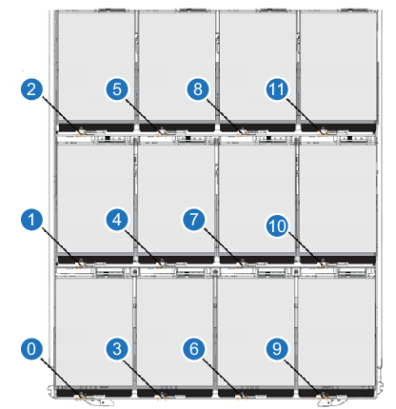
Array and Expansion Module Drive Drawers
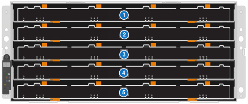
Each drawer can hold 12 drives in 3 rows. The drive locations are numbered 0 - 11.
Array (RBOD) and Expansion (EBOD) Module Drive Drawer
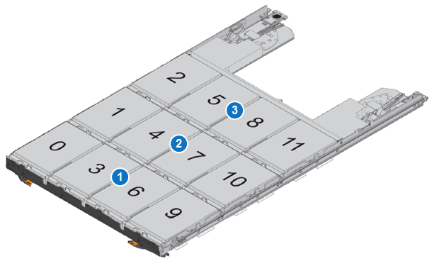
| Item | Drawer Drive Location |
|---|---|
| 1 | Front Row (Drives 0,3,6,9) |
| 2 | Middle Row (Drives 1,4,7,10) |
| 3 | Back Row (Drive 2,5,8,11) |
The 60 drive slots in the RBOD and EBOD are in the following locations.
| Drive Drawer | Drives in Draw | Drive Slot Number |
|---|---|---|
| 1 | 0 - 11 | 0 - 11 |
| 2 | 0 - 11 | 12 - 23 |
| 3 | 0 - 11 | 24 - 35 |
| 4 | 0 - 11 | 36 - 47 |
| 5 | 0 - 11 | 48 - 59 |
To prepare the failed drive for removal:
-
Locate the failed drive by observing the status LEDs on the front of each drive carrier in the DXi. You can remove the bezel from the Node if you have trouble viewing the LEDs.
 DXi9000 Node Drive Carrier LEDs
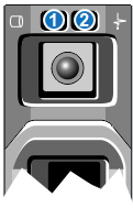
1 - Drive activity indicator (green) 2 - Drive status indicator (green and amber) LED Indicator Activity Drive activity indicator (green) - Flashing - Indicates hard disk drive activity.
Drive status indicator (green and amber) -
Off - Drive ready for insertion or removal
Note: The drive status indicator remains off until all drives are initialized after system power is applied. Drives are not ready for insertion or removal during this time.
- Blinks green two times per second - Identify drive/preparing for removal
- Blinks green, amber, and off - Drive predicted failure
- Blinks amber four times per second - Drive failed
- Blinks green slowly - Drive rebuilding
- Steady green - Drive online
- Blinks green three seconds, amber three seconds, and off six seconds - Rebuild aborted
Drive Carrier LEDs (DXi9000 SD Array or Expansion Module)
DXi9000 SD Array and Expansion Module LEDs
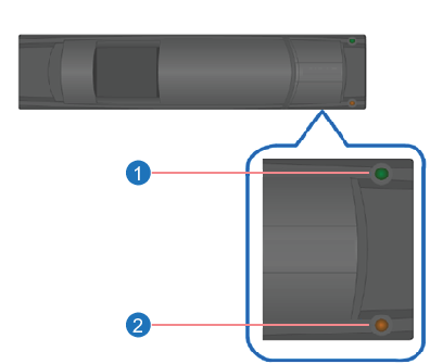
Item LED LED Color LED On LED Off 1 Activity Green Drive has power. No activity on the hard drive. Drive has no power. It is safe to remove the hard drive for service. Blinking Green There is activity on the hard drive.
Note: It is normal to see drive activity even when the DXi is not reading or writing data.
Drive has no power. It is safe to remove the hard drive for service. 2 Attention Amber The hard drive has failed and a service ticket is created. Contact Quantum customer support. Normal status. DXi9000/DXi9100 HD Array and Expansion Module LEDs
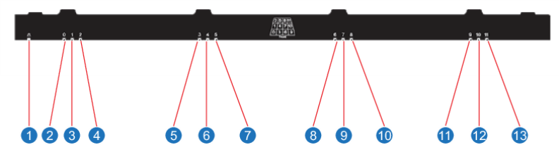
Item LED LED Color LED On LED Off 1 Attention Amber The hard drive has failed and a service ticket is created. Contact Quantum customer support. Normal status. 2 - 13 Drive activity for drives 0 - 11 in the drive drawer Green Drive has power. No activity on the hard drive. Drive has no power. It is safe to remove the hard drive for service. Blinking Green There is activity on the hard drive.
Note: It is normal to see drive activity even when the DXi is not reading or writing data.
Drive has no power. It is safe to remove the hard drive for service. There are 12 drive slots in each drawer numbered 0 - 11. Each drive utilizes an amber LED if the drive requires attention.
Hard Drive Drawer Drive LEDs
Location LED Status Indicator 0
Attention/Locate Drive LED 0 - Amber - The drive in the drawer requires attention.
- Off - The drive in the drawer is operating normally.
- Blinking - The is activity on the drive in progress.
1 Attention/Locate Drive LED 1 2 Attention/Locate Drive LED 2 3 Attention/Locate Drive LED 3 4 Attention/Locate Drive LED 4 5 Attention/Locate Drive LED 5 6 Attention/Locate Drive LED 6 7 Attention/Locate Drive LED 7 8 Attention/Locate Drive LED 8 9 Attention/Locate Drive LED 9 10 Attention/Locate Drive LED 10 11 Attention/Locate Drive LED 11 - If the failed drive is in the Node, remove the bezel from the front of the Node if you have not already done so.
-
Do one of the following:
Node - On the failed drive carrier, press the release button to extend the handle.
- Grasp the handle and pull the failed drive carrier outward 1 inch only.
Array or Expansion Module (SD) - On the failed drive carrier, press the release button on the left to extend the handle.
- Grasp the handle and pull the failed drive carrier outward 1 inch only.
Array or Expansion Module (HD) - Release the levers on the drive drawer.
- Using the levers, slide the drawer out.
-
On the failed drive carrier, raise the handle on the drive to vertical.
To install the replacement drive:
- Unpack the replacement drive.
-
Remove the failed drive.
Node - Slide the failed drive carrier out until it is free of the drive bay and set it aside.
Array or Expansion Module (SD) - Slide the failed drive carrier out until it is free of the drive bay and set it aside.
Array or Expansion Module (HD) - Release the levers on the drive drawer.
- Using the levers, slide the drawer out.
-
On the failed drive carrier, raise the handle on the drive to vertical.
Remove DXi9000 Drive

Remove DXi9000 SD Array or Expansion Drive

Remove DXi9000/DXi9100 HD Array or Expansion Drive
- Hold the replacement drive carrier in one hand, and with your other hand touch an exposed metal surface on the rack where the DXi is installed to discharge any static electricity buildup.
-
Do one of the following:
Node - Press the release button on the front of the drive carrier to open the release handle.
- Insert the drive carrier into the drive slot and slide until the drive connects with the backplane.
- Close the drive carrier release handle to lock the drive in place.
Array or Expansion Module (SD) - Press the release button on the left to extend the handle.
- Insert the drive carrier into the drive slot and slide until the drive stops.
- Slowly close the handle until the drive is seated and the handle clicks into place.
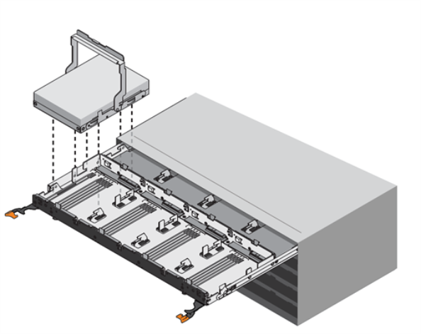
Array or Expansion Module (HD) - Raise the handle on the drive to vertical.
- Align the two raised buttons on the drive with the notches on the drawer. Then, pressing gently on the top of the drive, rotate the drive handle down until the drive snaps into place.
- Slide the drawer back in by sliding it from the center and closing both levers gently.
Use the status LEDs on the replacement drive to monitor the rebuilding process. The drive rebuild process takes approximately three hours (Node drive) or seventeen hours (Array or Expansion module drive), depending on system load. During the rebuild process, the remote management console displays Normal state in the system banner, and you may use the DXi normally.
Additional Information
- Don’t forget to reinstall the bezel on the front of the Node if you removed it.
- Don’t forget to return the failed drive to Quantum for proper credit (follow the instructions included with the replacement drive).