Expansion Module Rear Panel Indicators
LED indicators and buttons are located on the back of the Expansion modules (EBODs) (see Figure 1 and Table 1).
Figure 1: Expansion Module LED Indicators – Rear Panel
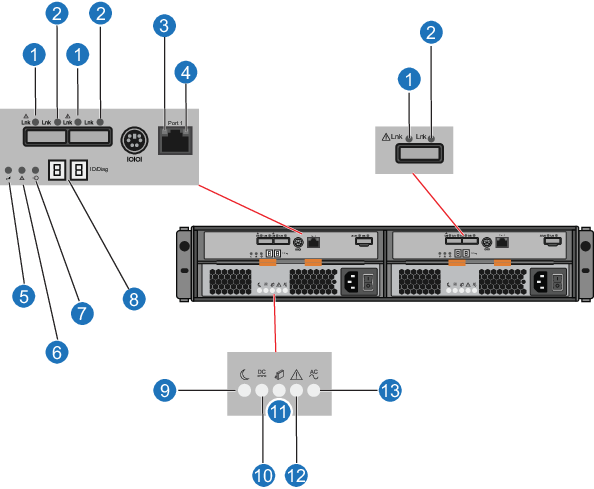
Table 1: Expansion Module LEDs and Buttons
| Items | Button/LED | Description |
|---|---|---|
| 1 | SAS host/expansion fault (amber) |
Both Off - cable unplugged. Fault Off and Activity On - all links operating. Fault On and Activity Off - at least one link active and at least one link fault. |
| 2 | SAS host/expansion activity (green) | Both Off - cable unplugged.
Fault Off and Activity On - all links operating. Fault On and Activity Off - at least one link active and at least one link fault. |
| 3 | Ethernet link rate (green) |
Solid - port speed 1000MB/sec. Off - port speed 10/100MB/sec. |
| 4 | Ethernet activity (green) |
Solid - link established. Blinking - indicates port activity. |
| 5 | Service action allowed (blue) | Solid - safe for Quantum field service. to remove ESM from slot. |
| 6 | Service action required (amber) |
Solid - ESM has failed and requires attention. Note: Fault light will be on during power up and will turn off after self-test sequence completes. |
| 7 | Power (green) | Solid - power is being applied to the ESM. |
| 8 | Seven segment display (green) | Displays tray ID and error code. (Displays 00 when the Array module is operating normally.) |
| 9 | Standby power (green) | Solid - main DC power is off and 5V standby power is on. |
| 10 | DC enabled (green) | Solid - DC power rails are within specified limits. |
| 11 | Service action allowed (blue) | Solid - safe for Quantum field service. to remove power supply from slot. |
| 12 | Service action required (amber) | Solid - power supply has failed and requires attention. |
| 13 | AC enabled (green) | Solid - power is being applied to the power supply and the power switch is on. |
| 14 | Power switch | Module power switch. |