DXi4800 Expansion Module EMM/IOM Features and Indicators
Each DXi4800 Gen1 Expansion module contains two enclosure management modules (EMMs). Each DXi4800 Gen2 Expansion module contains input/output modules (IOMs)
The figures below show the connectors located on the rear panel of the EMM and IOM.
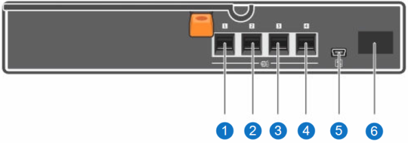
DXi4800 Gen1 Expansion Module EMM - Rear View
|
Item |
Indicator, Button, or Connector |
Icon |
Description |
|
1, 2, 3, 4 |
SAS port (Input or Output) |
|
Provides connection from the Node or another Expansion module. |
|
5 |
Debug port |
|
Not used. |
|
6 |
7-Segment Display |
Display the enclosure location in SAS Chain. |
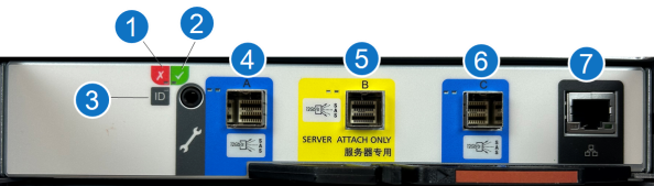
DXi4800 Gen2 Expansion Module EMM - Rear View
|
Item |
Indicator, Button, or Connector |
Icon |
Description |
| 1 | Module fault |

|
Amber LED On:
Amber LED Flashing:
|
| 2 | Power on or standby |

|
Green LED:
Amber LED:
No LED:
|
| 3 | Unit identification (UID) |

|
White LED:
|
| 4 | SAS port A |

|
Green LEDs:
Amber LEDS:
|
| 5 | SAS port B |
|
Not Used. |
| 6 | SAS port C |
|
Green LEDs:
Amber LEDS:
|
| 7 | Ethernet port |

|
Not Used. |