DXi4800 Array and Expansion Module Front Panel Features and Indicators
The figures below shows the controls, indicators, and connectors located behind the optional rack bezel on the front panel of the DXi4800 Gen1 and Gen2 Expansion Modules.
Note: Gen2 Expansion Modules are support on DXi4800 systems running DXi 4.9 Software and above.
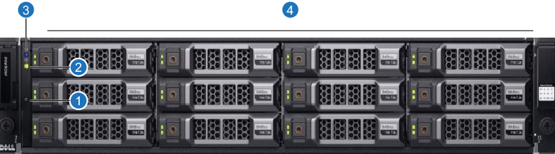
DXi4800 Gen1 Expansion Module - Front View
|
Item |
Indicator, Button, or Connector |
Description |
| 1 | System identification button |
The system identification button on the front control panel can be used to locate a particular enclosure within a rack. When the button is pressed, the system status indicators on the control panel and the EMM blink blue until the button is pressed again. |
| 2 | Power LED | The power LED lights when at least one power supply is supplying power to the enclosure. |
| 3 | Enclosure status |
The enclosure status LED glows when the enclosure power is on.
|
| 4 | Hard drives |
Twelve 3.5 inch hot-swappable hard drives (4 TB, 8 TB, or 16 TB each). Note: 8 TB HDDs supported with DXi Software 4.5.0 and above. Note: 16 TB HDDs supported with DXi Software 4.9.1 and above. |
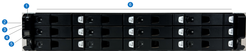
DXi4800 Gen2 Expansion Module - Front View
|
Item |
Indicator, Button, or Connector |
Description |
| 1 | Power LED |
The power LED lights when at least one power supply is supplying power to the enclosure. |
| 2 | Power on or standby |
Green LED:
|
| 3 | Module fault |
Amber LED:
|
| 4 | Unit ID (UID) |
Blue LED:
|
| 5 | LED display |
Green LED:
|
| 6 | Hard drives | Twelve 3.5 inch hot-swappable hard drives (8 TB each). |