DXi4800 Optional Network Card Installation
If you are installing the optional network card as part of a new DXi installation, do not use these instructions. Instead, follow the instructions in DXi4800 System Installation.
The following optional network card options are available for DXi4800 systems:
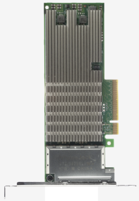
100 GbE Ethernet Dual-port Card
This card provides two 100 GbE (SFP28 optical or DAC copper) Ethernet ports.
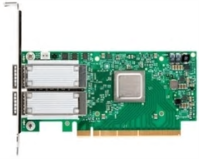
Note: Quantum recommends installing the dual port 100 GbE card in slots 1,4, and 8. If those slots are already used by existing 100 GbE cards, then use slot 7 for your fourth 100 GbE card. Slots 8, 4, and 1 have 16 PCIe lanes and slot 7 is has 8 PCIe lanes.
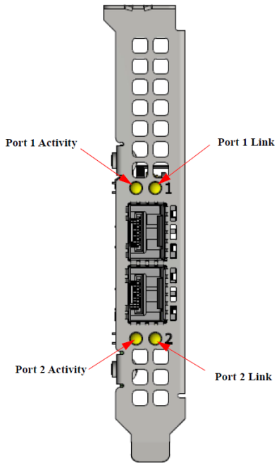
25 GbE Ethernet Dual-port Card
This card provides two 25 GbE (SFP28 optical or DAC copper) Ethernet ports.
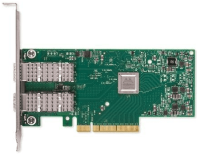
Note: Card shown has two LEDs per port. Your card may appear slightly different
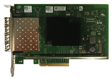
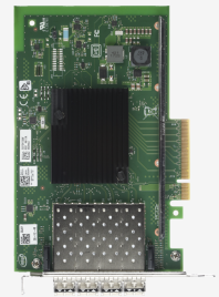
Quad-port 10 GbE Card
This card provides four 10 GbE (SFP+) Ethernet ports.
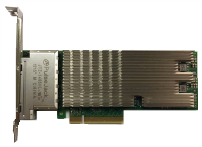
Quad-port 10 GBase-T Card
This card provides four 10 GBase-T Ethernet ports.
25 GbE Ethernet Dual-port Card
This card provides two 25 GbE (SFP28 optical or DAC copper) Ethernet ports.
Note: Card shown has two LEDs per port. Your card may appear slightly different
Quad-port 10 GbE Card
This card provides four 10 GbE (SFP+) Ethernet ports.
Quad-port 10 GBase-T Card
This card provides four 10 GBase-T Ethernet ports.
WARNING: To prevent the risk of electrical shock, bodily injury, or damage to the equipment, read all instructions and warnings in the Product Information Guide that shipped with your system.
Before you install the optional network card, make the following preparations:
Gather the Necessary Tools
The following tools are required for the optional network card installation:
- Small flat head screwdriver
Take ESD Precautions
Some components within the DXi system contain static-sensitive parts. To avoid damaging these parts while performing installation procedures, always observe the following precautions:
- Keep static-sensitive parts in their original shipping containers until ready for installation.
- Do not place static-sensitive parts on a metal surface. Place them inside their protective shipping bag or on an anti-static mat.
- Wear anti-static wrist bands when unpacking and handling the units, and avoid touching connectors and other components.
To shut down the system:
Caution: Before shutting down the DXi4800, make sure that all backup and replication jobs are finished, and that space reclamation activity is complete.
-
In the remote management console, navigate to the Utilities > Reboot & Shutdown page.
For information about accessing the remote management console, see the DXi4800 User's Guide.

-
Select Shutdown and click Apply. The shutdown process will take 20-30 minutes.
-
Close the browser window.
-
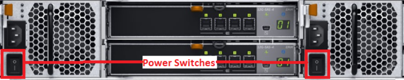
After the Node shuts down, turn off both power switches on the back of all installed Expansion modules (JBODs).
To remove the DXi4800 Node from the rack and remove the top cover:
WARNING: Opening or removing the system cover when the system is on may expose you to a risk of electric shock.
Caution: Use appropriate ESD precautions, including the use of a grounding strap, when working inside the Node.
- If installed, remove the front bezel by lifting the latch on the left side of the bezel.
-
Disconnect all power, SAS, Ethernet, and Fibre Channel cables from the rear of the Node. Make sure to label the cables so they can be easily identified when they are re-connected to the Node after the upgrade procedure is complete.
Caution: If cables are not re-installed correctly, the DXi system may not work properly after the card installation is complete.
-
Press the locking tab on either side of the Node, and pull the Node out from the rack until the inner rails lock.
Note: If necessary, remove the optional screws securing the Node to the front of the rack (behind the locking tab).
-
Locate the lock levers on the sides of the inner rails. Unlock each lever by rotating it up to its release position.
Removing the Node from the Rack
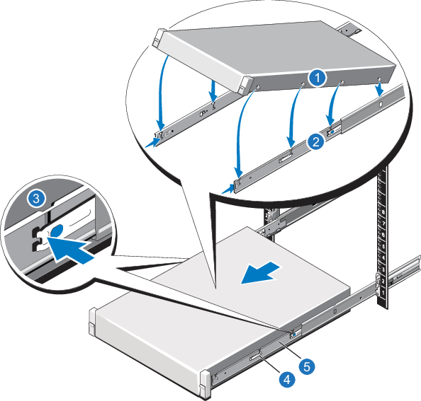
Item Description 1 Rear rail standoffs 2 Rear rail J-slots 3 Slide-release lock button 4 Lock lever 5 Inner slide rails - Grasp the sides of the Node firmly and pull it forward until the rail standoffs are at the front of the J-slots.
-
Lift the Node up and away from the rack and place it on a flat, stable surface.
WARNING: The DXi4800 Node weighs 72.9 pounds (33.1 kg). A minimum of two people are required to lift the chassis.
-
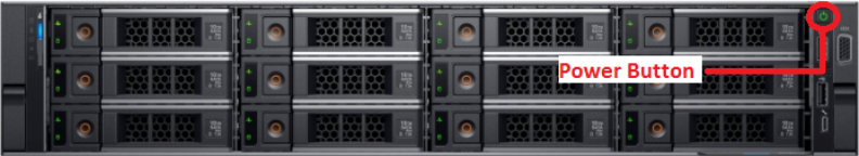
Press and hold the power button on the front of the Node for three seconds to fully drain the system of stored power prior to removing the cover.
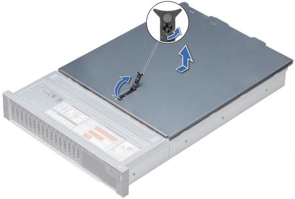
- On the Node cover, use a 1/4 inch flat head or Phillips #2 screwdriver to rotate the latch release counter clockwise to the unlocked position.
- Lift the latch until the system cover slides back and the tabs on the system cover disengage from the guide slots on the system.
-
Hold the cover on both sides, and lift the cover away from the system.
The following network card options are available for all DXi4800 configurations.
The additional ports can be used for management, replication, or data traffic.
Network Card Location
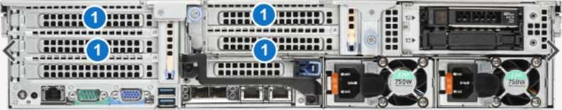
| Item | Card Option(s) |
|---|---|
| 1 | Install optional card in available empty slots (slots are labeled 1,2, 4, and 5. |
Caution: Use appropriate ESD precautions, including the use of a grounding strap, when performing this procedure.
To install an optional card in the DXi4800 Node:
-
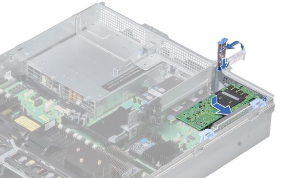
Lift the expansion card latch out of the slot.
The expansion card latch is located to the right of PCIe slots as you face the rear of the Node. The latch will remain attached to the system.
Installing an Optional Card in Riser 1
Installing an Optional Card in Riser 2
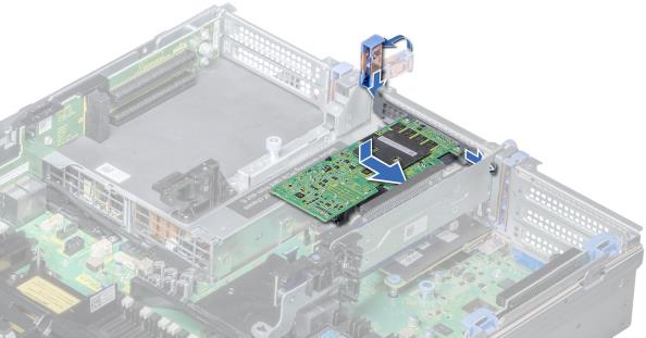
- Remove the metal slot covers from the slots by sliding it out of the slot.
- Holding the network card by its edges, position the card so that the connector on the card aligns with the expansion card connector on the riser.
- Insert the card-edge connector firmly into the expansion card connector until the card is fully seated.
- Push the expansion card latch down to lock the card in place.
- (Optical 10 GbE option only) Insert an SFP+ unit into each 10 GbE port on the card. (The SFP+ units are included with the optional 10 GbE network card.)
To close the DXi4800 Node cover and reinstall the rack:
- Lift the latch on the cover.
- Place the cover onto the Node chassis and offset the cover slightly back so that it clears the chassis hooks and lays flush on the chassis.
- Push down the latch to move the cover into the closed position.
-
Using a 1/4 inch flat head or Phillips #2 screwdriver, rotate the latch release lock clockwise to the locked position.
Replacing the Node Cover

- To reinstall the node in the rack, pull the inner slide rails out of the rack until they lock into place.
- Locate the rear rail standoffs on each side of the system and lower them into the rear J-slots on the slide assemblies.
- Rotate the Node downward until all the rail standoffs are seated in the J-slots.
-
Press the slide-release lock buttons on both rails and slide the system into the rack. (Make sure the Node is squarely aligned with the rack as you slide it in.)
Node Installation
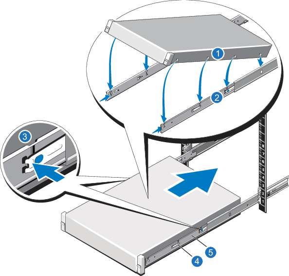
Item Description 1 Rear rail standoffs 2 Rear rail J-slots 3 Slide-release lock button 4 Lock lever 5 Inner slide rails - Reconnect all power, Ethernet, and Fibre Channel cables from the rear of the Node.
To turn on the system:
-
Turn on the DXi4800 system components in the following order:
-
Turn on both power switches on the back of each Expansion module. Wait 30 seconds for the Expansion modules to initialize. Verify on the front panel that the modules have power and there were no hard drive failures (Drive status indicator on hard drive blinks amber four times per second).
-
Press the power button on the front of the Node. Wait for the system to boot before continuing with the procedure. (This can take up to 30 minutes.)
Note: The system may reboot one or more times depending on the components that were installed. If all components are properly installed and cabled, the LEDs on all hard drives in the Node and the Expansion modules will be lit. (The top LED will be solid and the bottom LED will blink.)
-
-
Navigate to the Configuration > System > Network page in the remote management console and verify that the new network ports are available to the DXi.
The new ports should display under Bonding Details and Interface Details. They should also display on the Ethernet Port Backpanel Locations diagram at the bottom of the page.
Network Configuration
The current network configuration is not changed when adding the additional network card. To make use of the additional Ethernet ports, edit the settings on the Network page as needed.