DXi4700 Node Rear Panel Features
Figure 1 and shows the connectors located on the rear panel of the DXi4700 G1 Node. Figure 1 and shows the connectors located on the rear panel of the DXi4700 G2 Node. Table 1 describes each item.
Note: Refer to the port numbering label on the rear of the system to help you determine the correct port connections.
Caution: Do not disconnect any SAS cables from the Node during normal system operation. Unplugging a SAS cable while the system is powered on may result in data loss.
10 GbE Cable Types
Depending on the configuration, Quantum DXi4700 systems support one of the following 10 GbE cable types:
- 10 GbE optical cable lengths of up to 300 meters with OM3 cables and up to 100 meters with OM2 cables - Quantum recommends using the two 10 meter LC to LC type optical cables that are shipped with the DXi4700 system. Consult your 10 GbE optical switch/SFP documentation for additional information on optical cable requirements.
-
10 GbE Twinax cable - Quantum recommends using the approved 5 meter Twinax cable type that is shipped with the DXi4700 system. This cable is compatible with Cisco 5000 Series Data Center Class switches.
The 10 GbE Copper (Twinax) cable options that Quantum provides do not support all switches. Please note the supported switches during the purchase-configuration process, and if the Twinax cables supplied by Quantum are not compatible with your switch, then you will need to provide your own compatible Twinax cables from your switch vendor. Be sure to have these available before the system installation takes place.
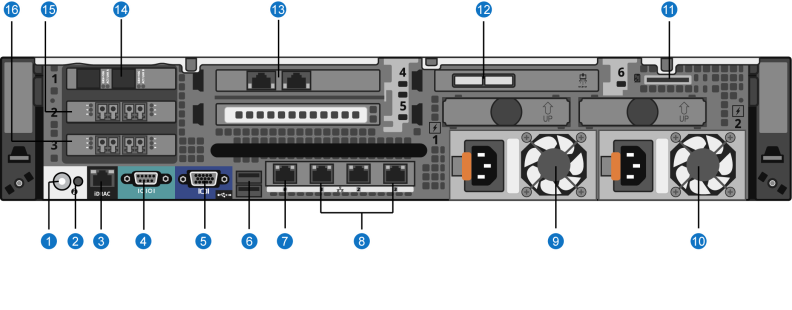
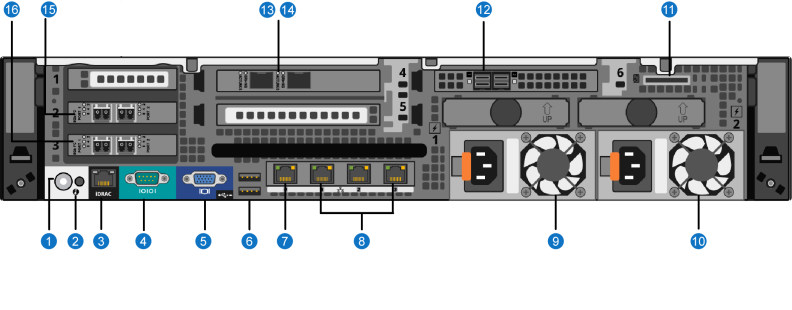
Table 1: DXi4700 Node - Rear Panel Connectors
|
Item |
Indicator, Button, or Connector |
Description |
|
1 |
System identification button |
Press to toggle the system ID on and off. The identification buttons on the front and rear panels can be used to locate a particular system within a rack. When one of these buttons is pressed, the system status indicator on the rear flashes until one of the buttons is pressed again. |
| 2 |
System identification connector |
Not used. |
|
3 |
iDRAC port |
For Quantum service use only. |
|
4 |
Serial connector |
For Quantum service use only. |
|
5 |
VGA connector |
Use of connected peripheral devices, such as a USB keyboard and mouse or a VGA display, is not supported and may cause incorrect system operation. |
|
6 |
USB 2.0 connectors (2) |
Use of connected peripheral devices, such as a USB keyboard and mouse or a VGA display, is not supported and may cause incorrect system operation. |
|
7 |
Service port |
For Quantum use only. |
|
8 |
3 x 1 GbE Ethernet ports |
For data ingest/read. |
|
9 |
Power supply (PSU1) |
750 watt hot-swappable power supply. |
|
10 |
Power supply (PSU2) |
750 watt hot-swappable power supply. |
|
11 |
vFlash media card slot |
Not used. |
|
12 |
(Configurations with Expansion modules only) DXi4700 G1 - 2 x 6 Gb SAS ports DXi4700 G2 - 2 x 12 Gb SAS ports |
For connection to Expansion modules (JBODs). |
|
13 |
DXi4700 G1 and G2 -(Optional) 2 x 10 GBase-T Ethernet ports. DXi4700 G2 only -(Optional) 2 x 10 GbE Ethernet ports |
For data ingest/read. Cannot be used with 2 x 10 GbE Ethernet ports .
For data ingest/read. Cannot be used with 2 x 10 GBase-T Ethernet ports . |
|
14 |
DXi4700 G1 only -(Optional) 2 x 10 GbE Ethernet ports |
For data ingest/read. Cannot be used with 2 x 10 GBase-T Ethernet ports |
|
15 |
(Multi-Protocol configurations only) 2 x 8 Gb Fibre Channel ports |
For PTT ingest/read. |
|
16 |
(VTL and Multi-Protocol configurations only) 2 x 8 Gb Fibre Channel ports |
For VTL ingest/read. |