Installing Components in the DXi4700 Node
If the DXi4700 shipped with additional Node components, you must install these additional components in the Node before installing the system in the rack and turning it on (see DXi4700 Installation Overview).
To install the additional Node components, see the following sections:
The Node has a total of 12 hard drive slots and ships from the factory with 6 hard drives (4 TB each) pre-installed in hard drive slots 0–5. Hard drive blanks are installed in hard drive slots 6–11.
For 19 TB and larger configurations, remove the hard drive blanks and install the provided 6 hard drives (4 TB each) in the Node (see Table 1). The additional hard drives must be installed in hard drive slots 6–11 (see Figure 1).
Caution: Do not remove the hard drives pre-installed in hard drive slots 0–5. If these drives are removed for any reason, you must re-install them in their original positions.
Table 1: DXi4700 Node Hard Drive Configurations
| DXi4700 Configuration | Node Hard Drives | Actions to Take |
|---|---|---|
|
5 TB 11 TB |
6 |
|
|
19 TB 27 TB 45 TB 63 TB 81 TB 99 TB 117 TB 135 TB |
12 |
|
Figure 1: Node Hard Drive Locations
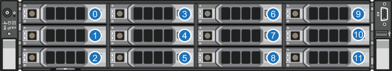
| Item | Description |
|---|---|
| 0 | HDD Slot 0 (Do not remove) |
| 1 | HDD Slot 1 (Do not remove) |
| 2 | HDD Slot 2 (Do not remove) |
| 3 | HDD Slot 3 (Do not remove) |
| 4 | HDD Slot 4 (Do not remove) |
| 5 | HDD Slot 5 (Do not remove) |
| 6 | HDD Slot 6 |
| 7 | HDD Slot 7 |
| 8 | HDD Slot 8 |
| 9 | HDD Slot 9 |
| 10 | HDD Slot 10 |
| 11 | HDD Slot 11 |
To install the additional hard drives in the DXi4700 Node:
Caution: Use appropriate ESD precautions, including the use of a grounding strap, when performing this procedure.
-
Remove the hard drive blank from each hard drive slot (slots 6–11):
- Grasp the front of the hard drive blank and press the release button.
-
Slide the hard blank out until it is free of the hard drive slot.
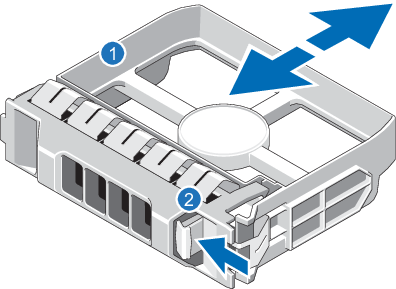
Item Description 1 Hard drive blank 2 Release button
-
Install a hard drive in each hard drive slot (slots 6–11):
Note: The additional hard drives are not keyed to a particular slot. You may install any hard drive in any slot, as long as it is installed in slot 6–11.
Caution: Use only the Quantum-supplied hard drives in the DXi4700 Node. Do not use any other drive (not even one taken from another DXi).
-
On the drive carrier, press the release button to extend the handle.
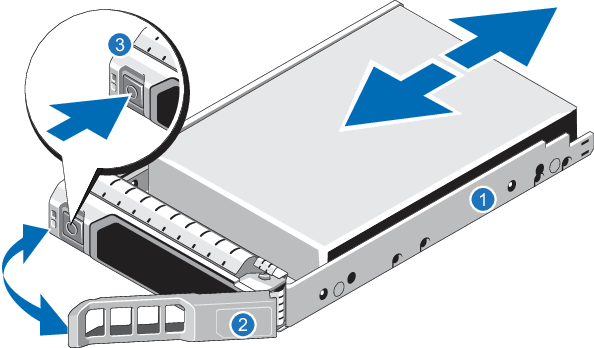
Item Description 1 Hard drive carrier 2 Hard drive handle 3 Release button -
Insert the drive carrier into the drive slot and push it in all the way.
-
Close the drive carrier handle to lock the drive in place.
-
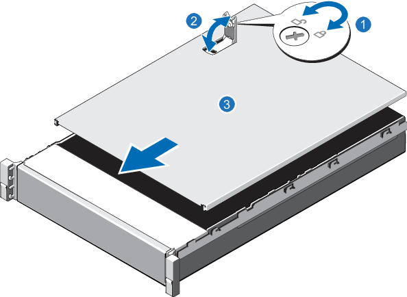
To open the DXi4700 Node cover:
WARNING: The DXi4700 G1 Node and Expansion module (JBOD) weigh 61.0 pounds (27.7 kg) and 62.6 pounds (28.4 kg) respectively. A minimum of two people are required to lift either chassis.
WARNING: The DXi4700 G2 Node and Expansion module (JBOD) weigh 49.4 pounds (22.4 kg) and 59.2 pounds (26.8 kg) respectively. A minimum of two people are required to lift either chassis.
- Set the Node on a flat, stable surface.
- Make sure that no cables (power, Ethernet, Fibre Channel, or SAS) are connected to the Node.
-
Press and hold the power button on the front of the Node for three seconds to fully drain the system of stored power prior to removing the cover.
1. Power Button -
On the Node cover, rotate the latch release lock counterclockwise to the unlocked position.
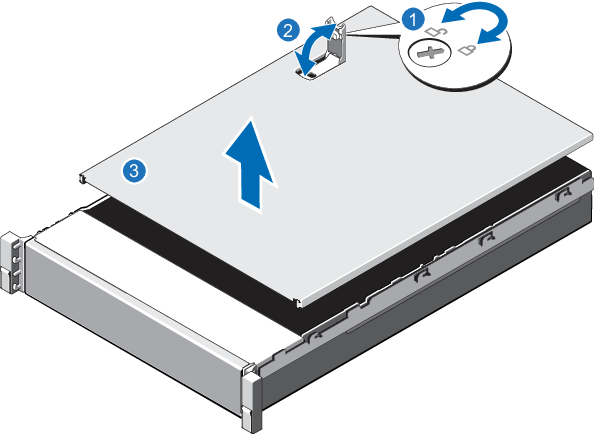
Item Description 1 Latch release lock 2 Latch 3 Node cover - Lift the latch on top of the Node and slide the cover back.
- Grasp the cover on both sides, and carefully lift the cover away from the Node.
-
-
Remove the cooling shroud by holding the touch points and lifting the shroud away from the Node.
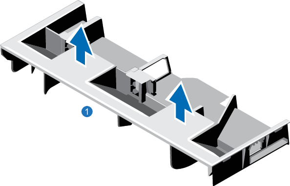
1. Cooling shroud
-
-
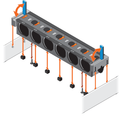
Remove the cooling-fan assembly by lifting the release levers upwards.
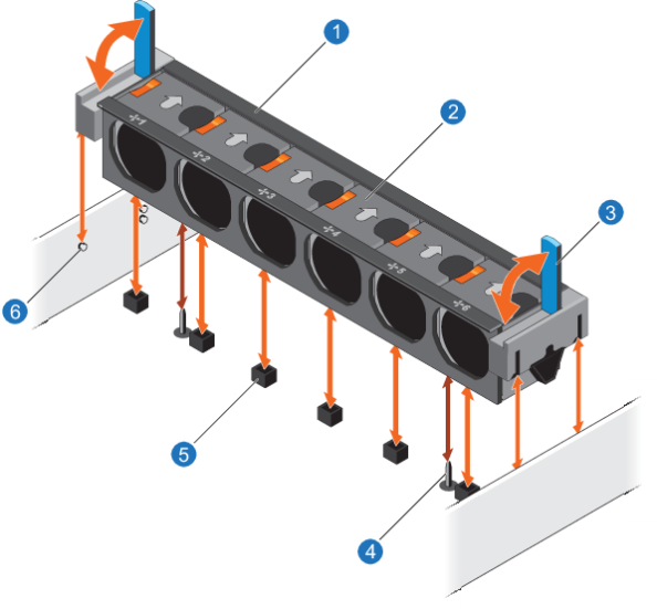
Item Description 1 Cooling-fan assembly 2 Cooling fan 3 Release lever (2) 4 Guide pin on the system board (2) 5 Cooling-fan connector (6) 6 Guide pin on the chassis (6) -
Lift the cooling-fan assembly out of the Node.
The next figure illustrates the interior of the DXi4700 Node with the cover removed.
Figure 2: Inside the DXi4700 Node
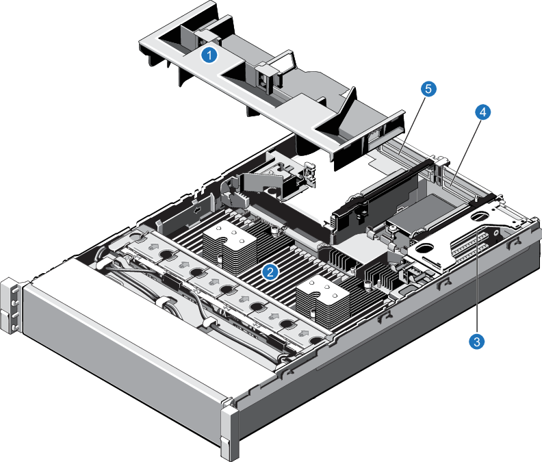
| Item | Description |
|---|---|
| 1 | Cooling shroud. |
| 2 | Memory modules. |
| 3 |
Expansion card riser 1
|
| 4 |
Expansion card riser 2
|
| 5 |
Expansion card riser 3
|
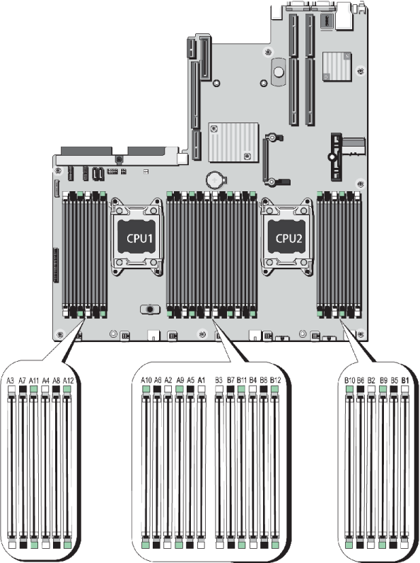
The Node has 24 memory sockets divided into 2 sets (A and B) of 12 slots each. Each set (A or B) is dedicated to one CPU. The Node ships from the factory with 4 GB memory modules (DIMMs) pre-installed in 8 memory sockets, for a total of 32 GB of memory.
For 45 TB and larger configurations, install the provided 4 GB memory modules in the Node. Memory modules must be installed in the correct sockets in order for the system to function properly.
WARNING: DAE and Veeam Memory Configurations
For DXi4700 systems with a Dynamic Application Environment (DAE) or Veeam configuration, the installation of additional memory modules is required after the initial system installation is complete. DO NOT install the additional memory at this time.
Note: Memory socket numbers are displayed on the clear window on the cooling shroud.
Table 2: DXi4700 Memory Configurations
| DXi4700 Configuration | Total System Memory | Actions to Take |
|---|---|---|
|
5 - 27 TB |
32 GB |
|
|
45 - 99 TB |
64 GB |
|
|
117 - 135 TB |
96 GB |
|
To install the memory modules in the DXi4700 Node:
Caution: Use appropriate ESD precautions, including the use of a grounding strap, when performing this procedure.
Caution: Handle the memory modules by the card edges and avoid touching the components on the memory module.
-
Remove the plastic memory blank from the socket by pressing down and out on the ejectors on each end of the socket until the memory blank pops out of the socket. (The plastic memory blanks are recyclable.)
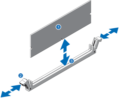
Item Description 1 Memory module 2 Ejector latch 3 Socket alignment tool -
Align the memory module’s edge connector with the alignment key of the memory module socket, and insert the memory module in the socket.
Note: The memory module socket has an alignment key that allows you to install the memory module in the socket in only one way.
- Press down on the memory module with your thumbs until the ejector latches snap into a locked position.
- Repeat steps 1–3 for each memory module.
-
Replace the cooling-fan assembly:
- Align the cooling-fan assembly slots with the guide pins on the chassis.
- Slide the cooling-fan assembly into the chassis.
- Lock the cooling-fan assembly into the chassis.
-
Replace the cooling shroud:
-
Align the tabs on the cooling shroud with the securing slots on the chassis.
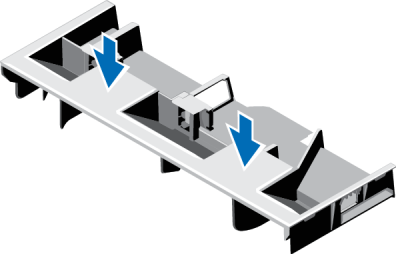
-
Lower the cooling shroud into the chassis until it is firmly seated.
Note: For proper seating of the cooling shroud in the chassis, ensure that the cables inside the system are routed along the chassis
-
The PERC H810 RAID controller (DXi4700 G1) or PERC H830 RAID controller (DXi4700 G2) allows you to connect up to three Expansion modules to the DXi4700 Node and is required for 45 TB and larger configurations. Install the provided H810/H830 RAID controller card in PCIe slot 6, located in expansion card riser 3.
Table 3: DXi4700 RAID Controller Configurations
| DXi4700 Configurations | Expansion Modules | Actions to Take |
|---|---|---|
|
5 TB 11 TB 19 TB 27 TB |
0 |
|
|
45 TB 63 TB |
1 |
|
|
81 TB 99 TB |
2 |
|
|
117 TB 135 TB |
3 |
Figure 4: DXi4700 G1 H830 RAID Controller Card Location
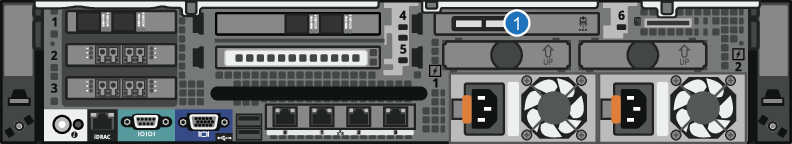
| Item | Card Option(s) |
|---|---|
| 1 | H810 RAID controller card |
Figure 5: DXi4700 G2 H830 RAID Controller Card Location
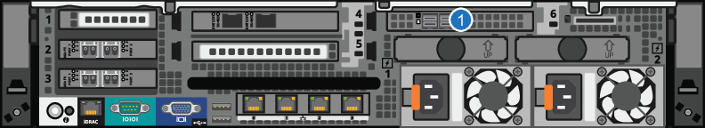
| Item | Card Option(s) |
|---|---|
| 1 | H830 RAID controller card |
To install the H810 or H830 RAID controller card in the DXi4700 Node:
Caution: Use appropriate ESD precautions, including the use of a grounding strap, when performing this procedure.
-
Lift the blue expansion card latch out of the slot.
The expansion card latch is located to the right of PCIe slot 6 as you face the rear of the Node. The latch will remain attached to the system.
Figure 6: Installing the H810/H830 Card in Riser 3
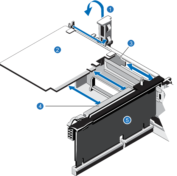
Item Description 1 Expansion card latch (blue) 2 H810/H830 card 3 Metal slot cover 4 Expansion card connector 5 Expansion card riser 3 -
Remove the metal slot cover from slot 6 by sliding it out of the slot.
-
Holding the H810 or H830 card by its edges, position the card so that the connector on the card aligns with the expansion card connector on the riser.
-
Insert the card-edge connector firmly into the expansion card connector until the card is fully seated.
-
Push the expansion card latch down to lock the H810 or H830 card in place.
The X520 network card provides two 10 GbE (SFP+) Ethernet ports and is an available option for all DXi4700 configurations. The 10 GbE ports can be used for management, replication, or data traffic. If ordered with the configuration, install the provided X520 10 GbE network card in the following locations:
- DXi4700 G1 in PCIe slot 1, located in expansion card riser 1.
- DXi4700 G2 in PCIe slot 4, located in expansion card riser 2.
A DXi4700 system can be configured with either the optional X520 10 GbE network card or X540 10 GBase-T network card. The system cannot be configured with both cards.
Table 4: DXi4700 Optional 10 GbE Configurations
| DXi4700 Configuration | Actions to Take |
|---|---|
|
5 TB 11 TB 19 TB 27 TB 45 TB 63 TB 81 TB 99 TB 117 TB 135 TB |
If ordered with the configuration, install an X520 10 GbE network card in PCIe slot 1 (DXi4700 G1) or PCIe slot 4 (DXi4700 G2). |
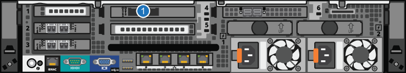
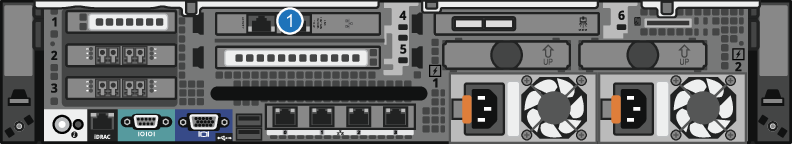
Figure 7: DXi4700 G1 Optional Network Card Location
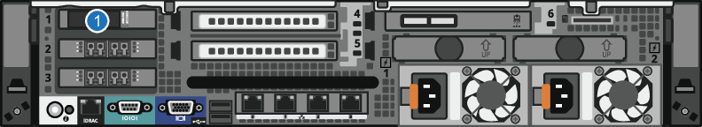
| Item | Card Option(s) |
|---|---|
| 1 | Install X520 10 GbE network card in slot 1. |
Figure 8: DXi4700 G2 Optional Network Card Location
| Item | Card Option(s) |
|---|---|
| 1 | Install X520 10 GbE network card in slot 4. |
DXi4700 G1: Installing the X520 Network Card
To install the X520 10 GbE network card in the DXi4700 Node:
Caution: Use appropriate ESD precautions, including the use of a grounding strap, when performing this procedure.
-
Holding the touch points, lift the expansion card riser 1 from the riser connector on the system board.
Figure 9: Removing and Installing the Expansion Card Riser 1
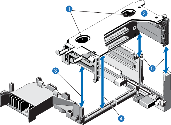
Item Description 1 Touch points 2 Expansion card riser 1 3 Front riser guide 4 Expansion card riser 1 connector 5 Back riser -
Press the tab to release the expansion card latch and rotate the latch away from the expansion card rise.
Figure 10: Installing the X520 Card in Riser 1
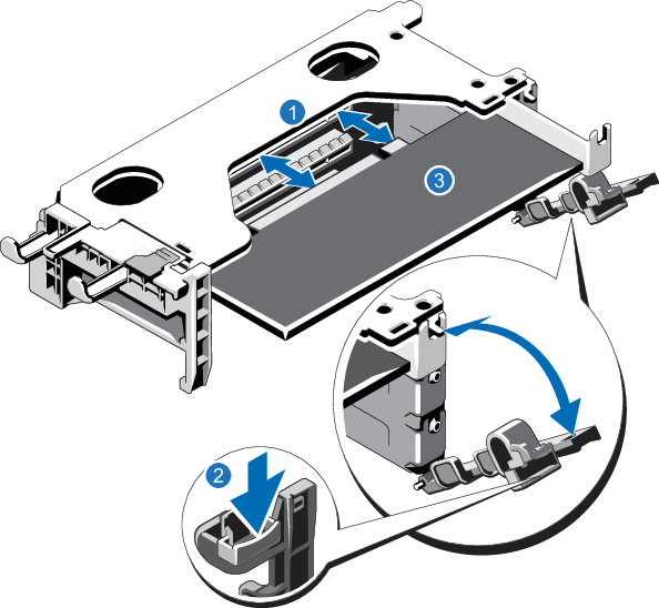
Item Description 1 Expansion card connector 2 Expansion card latch tab 3 X520 card -
Remove the metal slot cover from slot 1 by sliding it out of the slot.
-
Holding the X520 card by its edges, position the card so that the card edge connector aligns with the expansion card connector.
-
Insert the card edge connector firmly into the expansion card connector until the card is fully seated.
-
Close the expansion card latch.
-
Holding the touch points, insert the expansion card riser 1 into the riser connector on the system board.
-
(Optical 10 GbE option only) Insert an SFP+ unit into each 10 GbE port on the X520 card. (The SFP+ units are included with the optional 10 GbE network card.)
DXi4700 G2: Installing the X520 Network Card
To install the X520 10 GbE network card in the DXi4700 G2 Node:
Caution: Use appropriate ESD precautions, including the use of a grounding strap, when performing this procedure.
-
Lift the expansion card latch out of the slot.
The expansion card latch is located to the right of PCIe slot 4 as you face the rear of the Node. The latch will remain attached to the system.
Figure 11: Installing the X520 Card in Riser 2
Item Description 1 Expansion card latch (blue) 2 X520 card 3 Metal slot cover 4 Expansion card connector 5 Expansion card riser 2 -
Remove the metal slot cover from slot 4 by sliding it out of the slot.
-
Holding the X520 card by its edges, position the card so that the connector on the X520 card aligns with the expansion card connector on the riser
-
Insert the card-edge connector firmly into the expansion card connector until the card is fully seated.
-
(Optical 10 GbE option only) Insert an SFP+ unit into each 10 GbE port on the X520 card. (The SFP+ units are included with the optional 10 GbE network card.)
The X540 network card provides two 10 GBase-T Ethernet ports and is an available option for all DXi4700 configurations. The 10 GBase-T ports can be used for management, replication, or data traffic. If ordered with the configuration, install the provided X540 10 GBase-T network card in PCIe slot 4, located in expansion card riser 2.
A DXi4700 system can be configured with either the optional X520 10 GbE network card or X540 10 GBase-T network card. The system cannot be configured with both cards.
Table 5: DXi4700 Optional 10 GBase-T Configurations
| DXi4700 Configuration | Actions to Take |
|---|---|
|
5 TB 11 TB 19 TB 27 TB 45 TB 63 TB 81 TB 99 TB 117 TB 135 TB |
If ordered with the configuration, install an X520 10 GbE network card in PCIe slot 1 (DXi4700 G1) or PCIe slot 4 (DXi4700 G2) |
Figure 12: X540 Network Card Location
| Item | Card Option(s) |
|---|---|
| 1 | Install X540 10 GBase-T network card in slot 4. |
To install the X540 10 GBase-T network card in the DXi4700 Node:
Caution: Use appropriate ESD precautions, including the use of a grounding strap, when performing this procedure.
-
Lift the expansion card latch out of the slot.
The expansion card latch is located to the right of PCIe slot 4 as you face the rear of the Node. the latch will remain attached to the system.
Figure 13: Installing the X540 Card in Riser 2
Item Description 1 Expansion card latch (blue) 2 X540 card 3 Metal slot cover 4 Expansion card connector 5 Expansion card riser 2 -
Remove the metal slot cover from slot 4 by sliding it out of the slot.
-
Holding the X540 card by its edges, position the card so that the connector on the X540 card aligns with the expansion card connector on the riser.
-
Insert the card-edge connector firmly into the expansion card connector until the card is fully seated.
-
Push the expansion card latch down to lock the X540 card in place.
To close the DXi4700 Node cover:
-
Lift the latch on the cover.
Item Description 1 Latch release lock 2 Latch 3 Node cover - Place the cover onto the Node chassis and offset the cover slightly back so that it clears the chassis hooks and lays flush on the chassis.
- Push down the latch to move the cover into the closed position.
- Rotate the latch release lock in a clockwise direction to secure the cover.