DAE/Veeam Memory Module Installation
For DXi4700 systems with a DAE or Veeam configuration, the installation of additional memory modules is required. Memory modules must be installed in the correct sockets in order for the system to function properly.
WARNING: DO NOT install the additional memory modules to support a DAE or Veeam configuration until the DXi4700 system installation is complete.
To shut down the system:
-
In the remote management console, navigate to the Utilities > Reboot & Shutdown page.
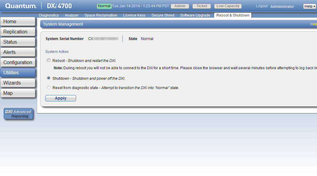
-
Select Shutdown and click Apply.
-
Close the browser window.
-
After the Node shuts down, turn off both power switches on the back of all installed Expansion modules (JBODs).
Figure 1: Expansion Module Power Switches - DXi4700
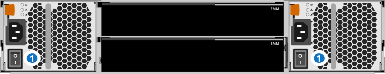
1 - Power Switches
To open the DXi4700 Node cover:
- Set the Node on a flat, stable surface.
- Make sure that no cables (power, Ethernet, Fibre Channel, or SAS) are connected to the Node.
-
Press and hold the power button on the front of the Node for three seconds to fully drain the system of stored power prior to removing the cover.
1. Power Button -
On the Node cover, rotate the latch release lock counterclockwise to the unlocked position.
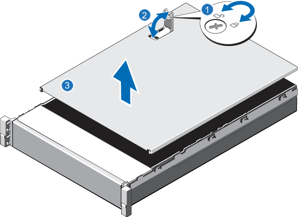
Item Description 1 Latch release lock 2 Latch 3 Node cover - Lift the latch on top of the Node and slide the cover back.
- Grasp the cover on both sides, and carefully lift the cover away from the Node.
-
-
Remove the cooling shroud by holding the touch points and lifting the shroud away from the Node.
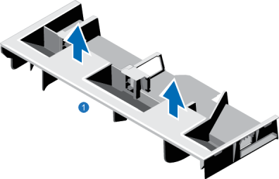
1. Cooling shroud
-
-
Remove the cooling-fan assembly by lifting the release levers upwards.
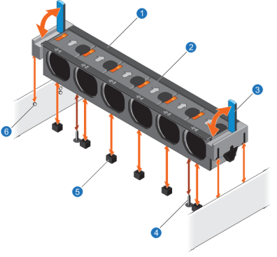
Item Description 1 Cooling-fan assembly 2 Cooling fan 3 Release lever (2) 4 Guide pin on the system board (2) 5 Cooling-fan connector (6) 6 Guide pin on the chassis (6) -
Lift the cooling-fan assembly out of the Node.
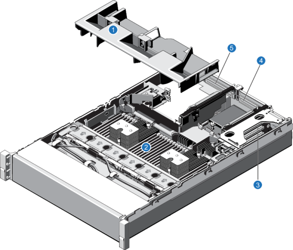
| Item | Description |
|---|---|
| 1 | Cooling shroud. |
| 2 | Memory modules. |
| 3 |
Expansion card riser 1
|
| 4 |
Expansion card riser 2
|
| 5 |
Expansion card riser 3
|
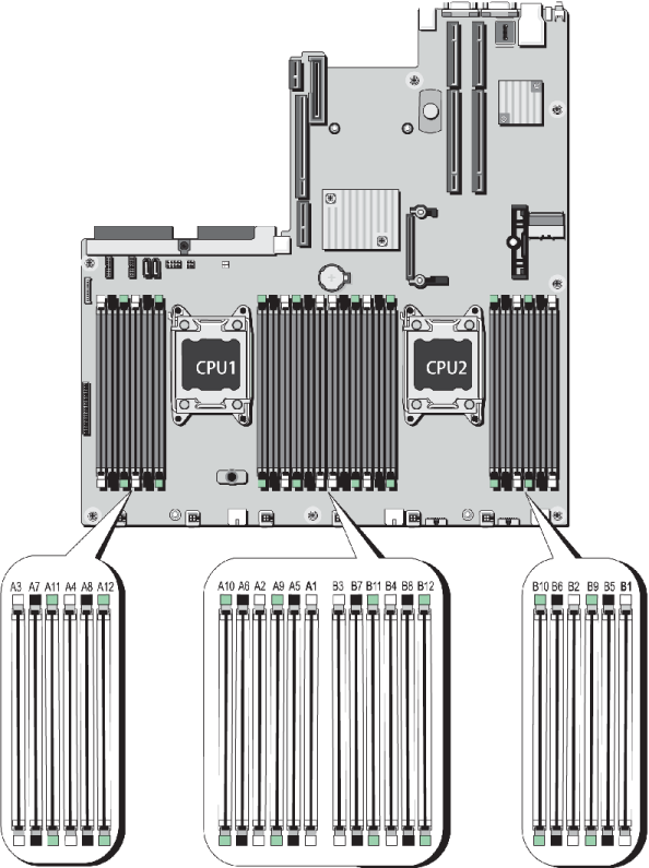
Install the additional DAE/Veeam memory modules in the Node. Memory modules must be installed in the correct sockets in order for the system to function properly.
Note: Memory socket numbers are displayed on the clear window on the cooling shroud.
Table 1: DAE or Veeam Memory Configurations
| DXi4700 Configuration | Total System Memory | Actions to Take |
|---|---|---|
|
5 - 27 TB |
64 GB |
|
|
45 - 99 TB
|
96 GB |
|
|
117 - 135 TB
|
128 GB |
|
Figure 2: Node Memory Module Locations
To install the memory modules in the DXi4700 Node:
Caution: Use appropriate ESD precautions, including the use of a grounding strap, when performing this procedure.
Caution: Handle the memory modules by the card edges and avoid touching the components on the memory module.
-
Remove the plastic memory blank or memory module from the socket by pressing down and out on the ejectors on each end of the socket until the memory blank pops out of the socket. (The plastic memory blanks are recyclable.)
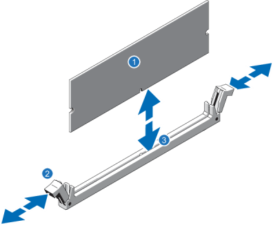
Item Description 1 Memory module 2 Ejector latch 3 Socket alignment tool -
Align the memory module’s edge connector with the alignment key of the memory module socket, and insert the memory module in the socket.
Note: The memory module socket has an alignment key that allows you to install the memory module in the socket in only one way.
- Press down on the memory module with your thumbs until the ejector latches snap into a locked position.
- Repeat steps 1–3 for each memory module.
-
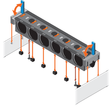
Replace the cooling-fan assembly:
- Align the cooling-fan assembly slots with the guide pins on the chassis.
- Slide the cooling-fan assembly into the chassis.
- Lock the cooling-fan assembly into the chassis.
-
Replace the cooling shroud:
-
Align the tabs on the cooling shroud with the securing slots on the chassis.
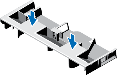
-
Lower the cooling shroud into the chassis until it is firmly seated.
Note: For proper seating of the cooling shroud in the chassis, ensure that the cables inside the system are routed along the chassis
-
To close the DXi4700 Node cover:
-
Lift the latch on the cover.
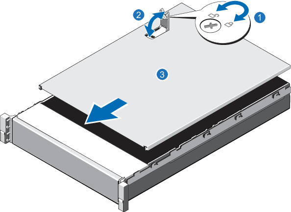
Item Description 1 Latch release lock 2 Latch 3 Node cover - Place the cover onto the Node chassis and offset the cover slightly back so that it clears the chassis hooks and lays flush on the chassis.
- Push down the latch to move the cover into the closed position.
- Rotate the latch release lock in a clockwise direction to secure the cover.
-
Pull the inner slide rails out of the rack until they lock into place.
Figure 3: Installing the DXi4700 Node in the Rack
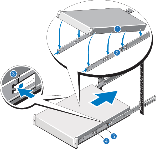
Item Description 1 Rear rail standoffs 2 Rear rail J-slots 3 Slide-release lock button 4 Lock lever 5 Inner slide rails - Locate the rear rail standoff on each side of the system and lower them into the rear J-slots on the slide assemblies.
- Rotate the Node downward until all the rail standoffs are seated in the J-slots.
- Press the slide-release lock buttons on both rails and slide the system into the rack. (Make sure the Node is squarely aligned with the rack as you slide it in.)
-
If applicable, replace the front bezel by inserting the right side of the bezel into the slots on the Node and then snapping the left side of the bezel into place.
To turn on the system:
-
Turn on the DXi4700 system components in the following order:
-
Turn on both power switches on the back of each Expansion module. Wait 30 seconds for the Expansion modules to initialize. Verify on the front panel that the modules have power and there were no hard drive failures (Drive status indicator on hard drive blinks amber four times per second).
Figure 4: Expansion Module Power Switches
1 - Power Switches -
Press the power button on the front of the Node. Wait for the system to boot before continuing with the procedure. (This can take up to 30 minutes.)
Note: The system may reboot one or more times depending on the components that were installed. If all components are properly installed and cabled, the LEDs on all hard drives in the Node and the Expansion modules will be lit. (The top LED will be solid and the bottom LED will blink.)
1 - Power Button -
For complete DAE/Veeam installation and configuration instructions, please refer to the DAE Installation Guide and Veeam Installation Guide on the DXi4700 Documentation Center (www.quantum.com/DXi4700Docs).