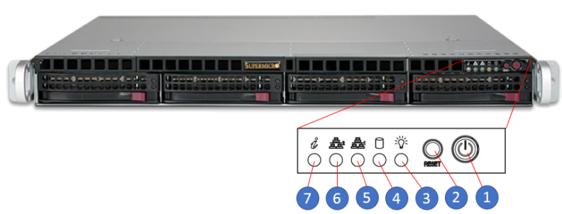
Control Panel LEDs and Switches

The control panel LEDs and switches are described in the table below.

Item Feature Description
1 Power Button

The main power button is used to apply or remove power from the power supply to the server.

  • Turning off system power with this button removes the main power but maintains standby power.
  • To perform many maintenance tasks, you must also unplug system before servicing.
2 Reset Button The reset button is used to reboot the system.
3 Power LED
  • Indicates power is being supplied to the system power supply.
  • This LED should normally be illuminated when the system is operating.
4 HDD LED Indicates activity on a hard drive when flashing.
5 NIC1 LED Indicates network activity on LAN port 1 when flashing.
6 NIC2 LED Indicates network activity on LAN port 2 when flashing.
7 Information LED
  • Continuously on and red: An overheat condition has occurred. (This may be caused by cable congestion.)
  • Blinking red (1 Hz): Fan failure: check for an inoperative fan.

  • Blinking red (0.25 Hz): Power failure: check for an inoperative power supply.

  • Solid blue: Local UID has been activated. Use this function to locate the server in a rack environment.

  • Blinking blue (300 msec): Remote UID has been activated. Use this function to locate the server from a remote location.