minute read
Hardware Overview
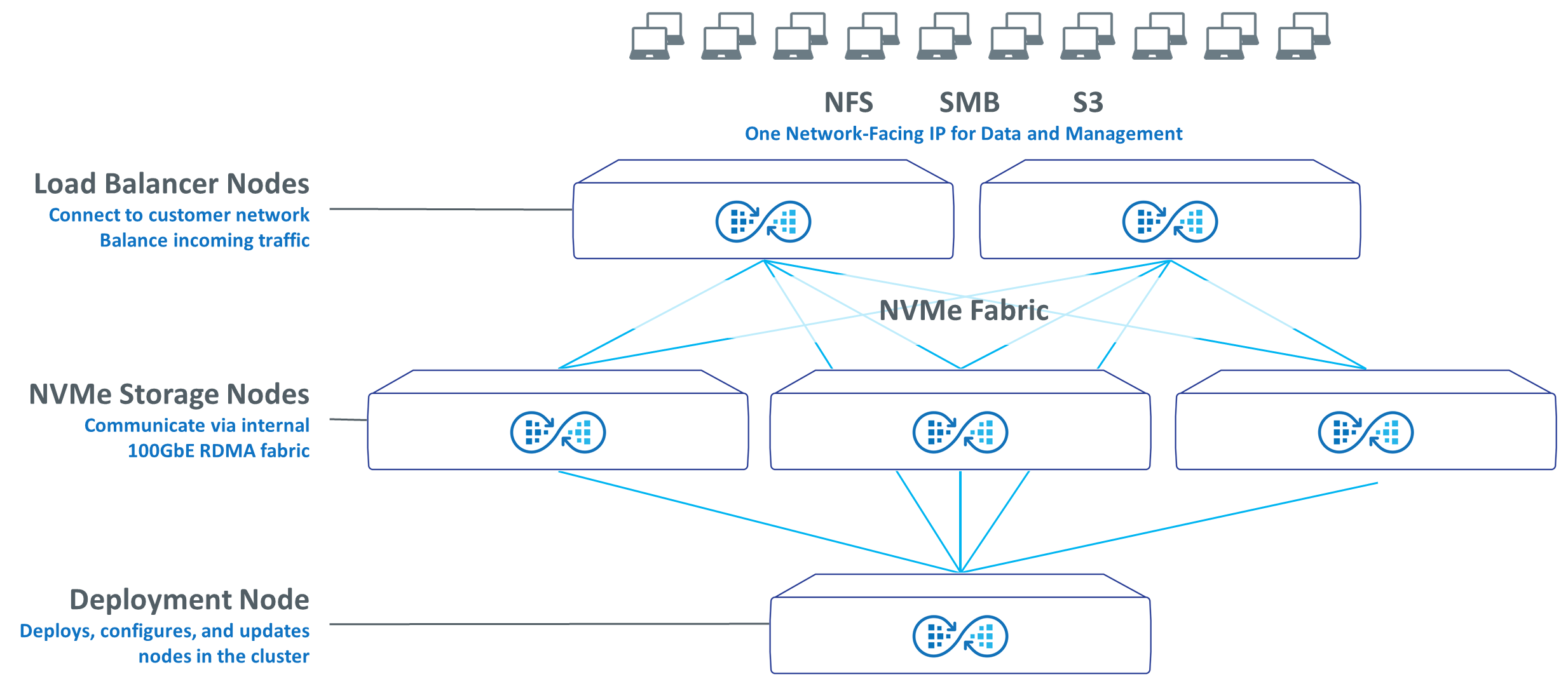
A Myriad cluster is comprised of two Load Balancer Nodes, which are switches that connect to the customer network and balance incoming traffic.
NVMe Storage Nodes communicate with each other and the Load Balancer Nodes using an internal 100GbE NVMe/RDMA fabric, providing for a fully distributed all-flash architecture that provides consistent low latency performance for both high-bandwidth and high-IOPS workloads.
The Deployment Node is not in the data path, and is a basic switch that is only used when deploying new software, or when new nodes are added to the cluster. As noted, the cluster is comprised of a number of microservices that are orchestrated by Kubernetes. Kubernetes is used to orchestrate the cluster, maintain the correct state of the cluster, and more.
It is easy to scale the cluster non-disruptively by adding more NVMe storage nodes. Over time, Quantum plans to add different server and storage options, including high density storage nodes, higher density drives, faster servers, and more.
With Myriad, the future is built-in – simply modify and adapt your cluster with more performance and/or more capacity to meet your requirements.
| Cluster Components | Storage Node | Load Balancer Node | Deployment Node |
|---|---|---|---|
| Description | Standard server that provides compute and storage | Switch that connects to customer network | Switch that deploys software, configures other nodes |
| Cluster Requirements | 5 cluster | 2 per cluster | 1 per cluster |
| Size | 1U | 1U | 1U |
| CPU and Memory | 64-Core CPU, 1 TB RAM, PCIe 4 | n/a | n/a |
| Drives Per Server | 10 NVMe flash drives per server | n/a | n/a |
| Flash Storage Options | Single-ported TLC drives 15.36 TB |
n/a | n/a |
| Networking Ports | 4 x 100 GbE | 32 x 100 GbE | 48 x 1 GbE |
| Management Ports | 10 GbE RJ-45 10 GbE RJ-45 IPMI/BMC |
1 GbE RJ-45 | 1 GbE RJ-45 |
| Dual Power | Yes | Yes | Yes |
| Redundant Fans | Yes | Yes | Yes |
The NVMe storage node communicates with other storage nodes and the Load Balancer Nodes using an internal 100GbE NVMe/RDMA fabric, providing for a fully distributed all-flash architecture that provides consistent low latency performance for both high-bandwidth and high-IOPS workloads.
Hardware
-
1U Server running Ubuntu Linux, 1 TB RAM, 64-core CPU, PCIe4
-
4 x 100 GbE SFP-28 ports (2 x dual 100 GbE NICs)
-
1 x 10 GbE RJ-45 mgmt port + 1 10 GbE RJ-45 IPMI/BMC port
-
10 x 2.5” NVMe flash drives
-
Dual power, redundant fans
Functions
-
House all NVMe storage devices
-
House compute for data storage operations
-
Run all operations in Kubernetes pods
-
Storage target / initiator / allocation / presentation
-
Distributed key/value store
-
Replication
-
System monitoring, analytics, API gateway
-
Unified User Interace (UUI), Cloud Based Analytics (CBA)
-
Network Port Assignment
-
4 x 100 GbE to Load Balancer Nodes
-
2 x 10 GbE to Deployment Node (Management and IPMI/BMC)
Features
| Item | Description |
|---|---|
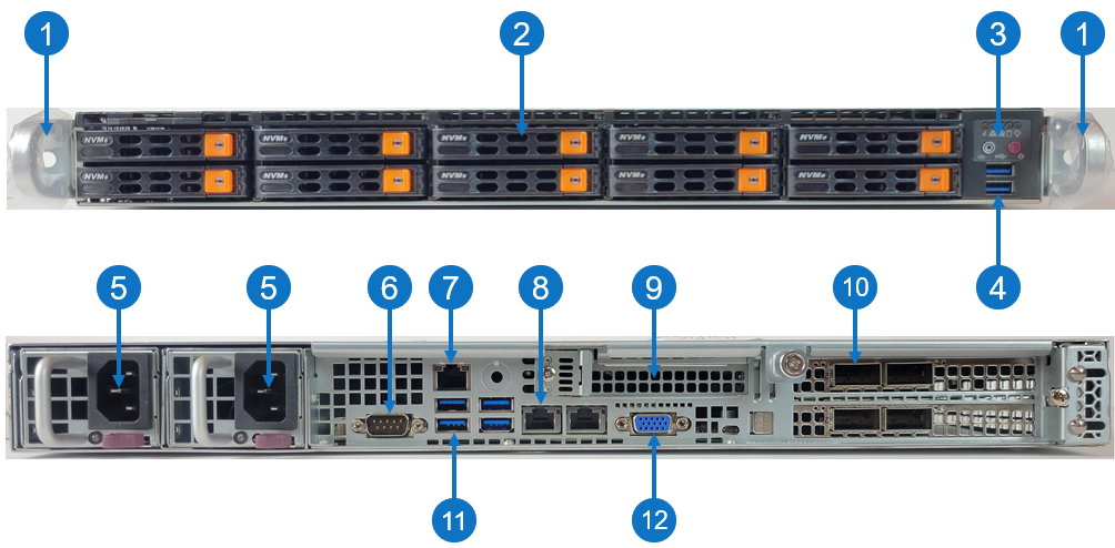
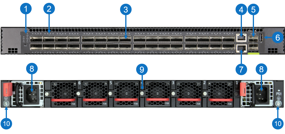
| 1 |
Front handles WARNING: Do not pick up the node with the front handles. They are designed to pull the system from a rack only. |
| 2 | (10) Drive bay for 2.5" hot-swap drive carrier |
| 3 | Control panel |
| 4 | (2) USB storage port |
| 5 |
(2) Hot-swappable redundant, load-sharing AC power supply unit (PSU)
|
| 6 | COM port |
| 7 | RJ-45 100/1,000 BASE-T IPMI port |
| 8 | (2) RJ-45 1,000/10,000 BASE-T management port (left port # 1 and right port # 2) |
| 9 | Expansion card slot for low-profile, half length (LPHL) expansion (add-on) card |
| 10 | (4) QSFP28 100 G ports |
| 11 | (4) USB storage port |
| 12 | VGA port |
Control Panel LEDs
|
Item |
LED/Button |
Indication/Function |
|
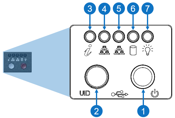
1 |
Power button |
Use the main power switch to apply or remove power to the node. If you turn off the system power with this button, then the process removes the main power but keeps standby power supplied to the node.
Caution: You must unplug the AC power cord before you service the node. |
| 2 | Unit identifier (UID) button |
Press the button to illuminate an LED on both the front and rear of the node for easy system location in a rack configuration. The LED remains on until the button is pushed a second time.
Note: A UID button on the rear of the node serves the same function. |
| 3 | Universal information |
|
|
4 |
1,000/10,000 BASE-T RJ-45 port |
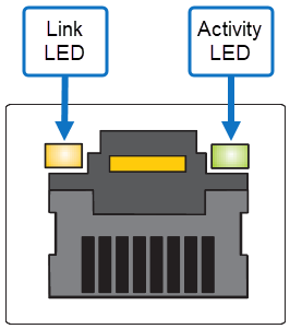
Indicates network activity on the management port # 1. The physical port LEDs represent the following:
Link LED
Activity LED
|
|
5 |
1,000/10,000 BASE-T RJ-45 port |
Indicates network activity on the management port # 2. The physical port LEDs represent the following:
Link LED
Activity LED
|
| 6 | SSD | When flashing, indicates drive activity. |
| 7 | Power | Indicates power is supplied to the system's power supply units; this LED illuminates when the system is operating normally. |
The load balancer nodes is a switch that connects to the customer network and balances incoming traffic.
Hardware
-
1U Ethernet switch running SONiC Linux
-
32 x 100 GbE SFP-28 ports + 1 GbE RJ-45 management port
-
Dual power, redundant fans
Functions
-
Connect to the customer network
-
Present one customer-facing IP address across all load balancer nodes for all customer I/O and management traffic
-
Hide internal cluster networking using NAT
-
Load balance traffic in to storage nodes and out to customer
Network Port Assignment
-
Up to 12 x 100 GbE to customer network
-
Up to 20 x 100 GbE to Storage Nodes (2 per)
-
1 GbE to Deployment Node
Features
| Item | Description |
|---|---|
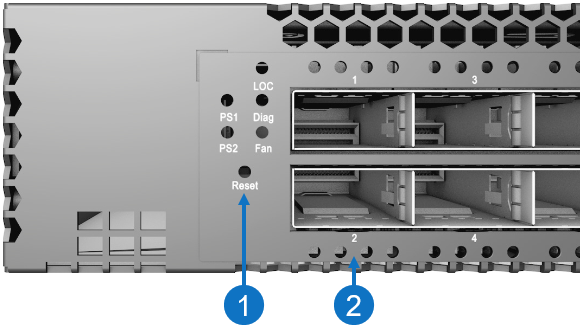
| 1 | System LEDs |
| 2 | Port indicators |
| 3 |
(32) QSFP28 100G ports Note: Port 1 through port 20 is used to connect to the NVMe storage node(s), and port 21 through port 32 is used to connect to a customer-provided switch (uplink). |
| 4 | RJ-45 100/1000BASE-T management port |
| 5 | (2) SFP28 10G management ports |
| 6 | USB storage port |
| 7 | RJ-45 serial console port |
| 8 | (2) Hot-swappable redundant, load-sharing AC power supply unit (PSU) |
| 9 | (6) Hot-swappable redundant fan (fan tray) |
| 10 | Grounding point |
System and Port LEDs
|
Item |
LED/Button |
Indication/Function |
|
1 |
Reset button |
|
| System |
Green: OK Amber: Fault |
|
|
PSU |
Green: OK Amber: Fault |
|
| Fan |
Green: OK Amber: Fault |
|
| 2 | QSFP28 100G port |
Each port contains four LEDs that indicate valid links in the following modes:
|
| Located on the SFP28 port | SFP28 10G management port |
Green: 10G link Amber: 1G link |
The deployment node is a basic switch that is only used when deploying new software, or when new nodes are added to the cluster.
Hardware
-
1U Ethernet switch running SONiC Linux
-
48 x 1 GbE RJ-45 ports + 1 GbE RJ-45 management port
-
2 x 100 GbE stacking ports
-
Dual power, redundant fans
Functions
-
The only component that ships with Quantum software pre-installed
-
Hosts initial configuration process
-
Deploys software and configuration to bare-metal storage nodes and load balancer nodes
-
Initial configuration, node addition, node replacement
-
-
Manages software upgrades
Network Port Assignment
-
1 GbE management port to customer network for setup/recovery
-
Up to 48 x 1 GbE to Storage Nodes and Load Balancer Nodes (including Spine Nodes)
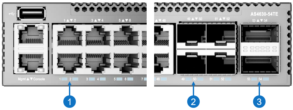
Features
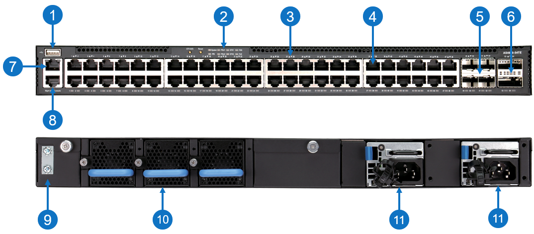
| Item | Description |
|---|---|
| 1 | USB storage port |
| 2 | System LEDs |
| 3 | Port indicators |
| 4 | (48) 10/100/1000BASE-T RJ-45 2.5G ports |
| 5 | (4) SFP28 10G/25G ports |
| 6 | (2) QSFP28 40G/100G uplink or stacking ports |
| 7 | RJ-45 100/1000BASE-T management port |
| 8 | RJ-45 serial console port |
| 9 | Grounding point |
| 10 | (3) Hot-swappable redundant fan (fan tray) |
| 11 | (2) Hot-swappable redundant, load-sharing AC power supply unit (PSU) |
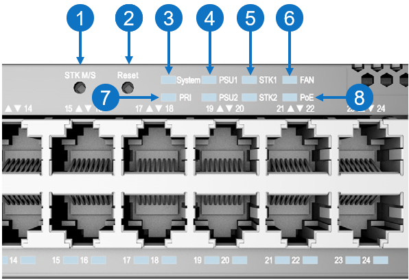
System LEDs and Buttons
|
Item |
LED/Button |
Indication/Function |
|
1 |
STK M/S button |
|
|
2 |
Reset button |
|
| 3 | System LED |
Green: OK Amber: Fault |
|
4 |
PSU LEDs |
Green: OK Amber: Fault |
| 5 | STK LEDs |
Green: Stacking ports active |
| 6 | FAN LED |
Green: OK Amber: Fault |
| 7 | PRI LED |
Green: Primary unit Amber: Secondary unit |
| 8 | PoE LED | Off |
Port and CRU/FRU LEDs
|
Item |
LED/Button |
Indication/Function |
|
1 |
10/100/1000BASE-T RJ-45 2.5G port |
Green: Link Blinking: Activity |
|
2 |
SFP28 10G/25G port |
White: 25G link Green: 10G link Blinking: Activity |
| 3 | QSFP28 40G/100G uplink or stacking port |
White: 100G link Green: 40G link Blinking: Activity |
| Located on PSU | PSU status |
Green: OK Red: Fault or fan failure |
| Located on fan/fan tray | Fan tray status |
Green: OK Red: Fault |