minute read
Hardware Overview
The Quantum F2100 is Quantum’s ultra-fast and highly-available storage array for editing, rendering, and processing of video content and other large unstructured data sets in a StorNext shared storage environment.
The F2100 is part of a StorNext shared storage environment, and is supported by the following host software interfaces including:
- StorNext – see the StorNext Documentation Center
Overview
-
Requires a minimum of QBSP software version 2.4.0.
-
Backward compatibility with F2100/F2000 system is not supported.
-
DIMM memory expansion upgrade options are not supported.

|
Item |
Component |
|---|---|
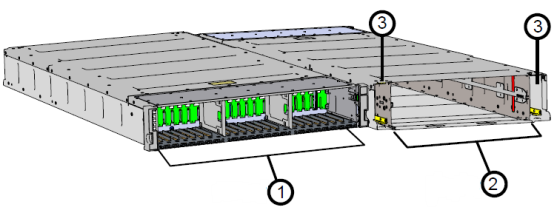
|
1 |
Drive Bays at the front of the system:
|
|
2 |
Redundant power supply units (PSUs) at the rear of the system. PSU A is on the left and PSU B is on the right. |
|
3 |
Controller A (top). Redundant/failover operations supported with Controller B (bottom). |
| 4 | Controller B (bottom). Redundant/failover operations supported with Controller A (top). |
Storage - Capacities and LUN Configuration
Storage Capacities
The F2100 contains 12 or 24 dual-ported NVMe SSDs and is available in different total capacities:
|
SSD Quantity |
Raw System Capacity |
SSD Size |
|
24 |
92.16 TB |
3.84 TB |
|
24 |
184.3 TB |
7.68 TB |
| 24 | 368.64 TB | 15.36 TB |
| 24 | 737.28 TB | 30.72 TB |
|
12 |
46.08 TB |
3.84 TB |
|
12 |
92.16 TB |
7.68 TB |
| 12 | 184.32 TB | 15.36 TB |
| 12 | 368.64 TB | 30.72 TB |
LUN Configuration
The F2100 is designed for a StorNext shared storage environment, and is pre-configured with 2 logical units (LUNs) in a RAID6 configuration. It is optimized for high-resolution work-flows.
The LUNs are intended for data storage, not metadata storage. Quantum recommends using a separate storage array for metadata storage.
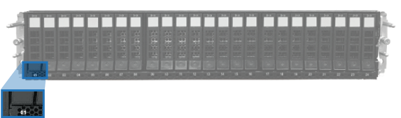
System - Front
The front of the F2100 contains a drive bay that includes 24 Non-Volatile Memory Express (NVMe) Solid State Drives (SSDs) for fully-populated systems, or 12 drives for half-populated systems.
The SSDs are numbered from 01 to 24, from left to right. The drive slot number is printed at the bottom of the chassis below the SSD drive assemblies:
System - Rear
Controller PCIe Slot Locations
Note: The F2100 is not available with a combination of both 32 Gb FC cards and 100 GbE cards installed in the same system.
F2100 Rear - PCIe Slot Locations
Top illustration: FC (Fibre Channel) interface card configuration
Bottom illustration: Ethernet interface card configuration
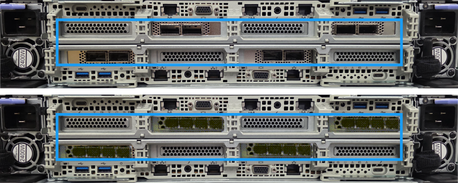
The F2100 is available in an FC (Fibre Channel) or Ethernet interface card configuration.
- FC model: 2 x quad-port 32 Gb FC cards per controller. FC cards are installed in PCIe slot 1 and slot 3.

- High-speed Optical Ethernet model: 2 x dual-port 100 Gb Ethernet (GbE) cards per controller. Ethernet cards are installed in PCIe slot 1 and slot 3.

Port Connections
F2100 Rear Port Connections

System LEDs
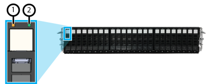
The front chassis LEDs are available on the left side of the system and are visible with or without the Quantum bezel installed:

|
Item |
LED |
Action |
|
1 |
Power |
Off: Power off Green solid: Power on |
|
2 |
Identify |
• Off: Chassis is not being identified • Blue: Chassis is being identified |
|
3 |
Fault |
Off: No faults reported Amber (1Hz Blinking): Warning error Amber (4Hz Blinking): Critical error Amber solid: Fault conditions exist |
The rear controller LEDs are available on both controllers.

|
Item |
LED |
Action |
|
1 |
Power |
Off: Controller power off Green solid: Controller power on |
|
2 |
Active |
Off: Controller not active Green: Controller is active |
|
3 |
Fault |
Amber solid: Fault conditions exist Off: Normal operation |
|
4 |
BBU Status |
Not used |
|
5 |
BBU Fault |
Not used |
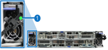
The PSU Fault led is located in the same position on PSU A and PSU B. Location and description of the LED:
|
Item |
LED |
Action |
|
1 |
Power |
Off: PSU power off Green solid: PSU power on Amber solid: Fault, failure, or AC disconnection on PSU |
The SSD LEDs are located at the top of SSD drive carriers. Locations and descriptions of the LEDs:
|
Item |
LED |
Action |
|
1 |
Drive Fault LED |
Amber (solid or blinking): Degraded drive reported. Replace the drive. |
|
2 |
Drive Link/Active |
Off: No drive present Green: Drive present Green (Blinking): Drive active |
System Components
Chassis
The chassis is the primary housing that contains and connects all F2100 components.
The chassis is 2U in height and contains the drive bay, located at the front, which houses all 24 of the data SSDs. The rear of the chassis contains PSU bays and two controller bays.
The major system components, such as the fan modules, CPUs, memory, and M.2 boot drives, are all contained within each of the two controllers.
|
Item |
Description |
|
1 |
Drive Bay at the front of the system |
|
2 |
Dual controller bays at the rear of the system |
|
3 |
Dual PSU bays at the rear of the system |
Controller
The F2100 chassis contains redundant controllers that each contain and connect system components. The major system components, such as the interface cards, fan modules, CPUs, DIMMs, and M.2 Boot Drives, are all contained inside the controllers.
The redundancy of the controllers is designed so that the system can run on one controller in the event that the other controller fails. The controllers can be hot-swapped to ensure that the F2100 is always available.
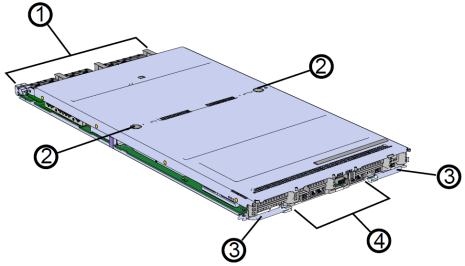
|
Item |
Description |
|
1 |
Controller connectors |
|
2 |
Cover release buttons |
|
3 |
Controller release latches |
|
4 |
Rear I/O |
Fan Modules
The fan module includes two fans and provides the primary cooling for the F2100. The fan module is installed inside each controller. It is located close to the controller components to provide efficient cooling to system components.
An F2100 system contains 10 fan modules, with five fan modules in each controller.
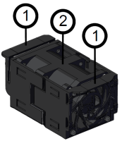
|
Item |
Description |
|
1 |
Fan handles used to lift the fan module out from the controller |
|
2 |
Fan module (which includes two fans) |
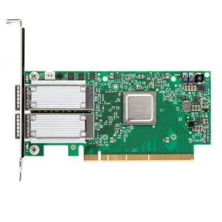
Interface Cards
The F2100 array can include one of the following Fibre Channel (FC) or Ethernet interface card configurations.
Note: The F2100 is not available with both FC cards and Ethernet cards installed in the same system.

PIB Canisters
The Power Interface Board (PIB) canister houses the PIB that extends the connection of the PSU to the midplane of the chassis. The PIB canister contains a PSU connector that attaches to the PIB. The other end of the PIB canister contains a card edge connection that fits into a midplane connector.
|
Item |
Description |
|
1 |
PIB card edge |
|
2 |
PSU connector |
|
3 |
PIB Canister |
|
4 |
Handle |
Power Supply Units (PSUs)
The F2100 contains two redundant, hot-swappable 2000 W power supply units (PSUs). Each PSU requires an input voltage of between 200-240 AC. The PSUs are 80 Plus™ Platinum certified, and utilize C14 power cable receptacles. PSU specifications:
|
Specifications |
Value |
|
Power Output |
2000 W |
|
80 PLUS Standard |
80 Plus™ Platinum |
|
Input Voltage |
200-240 VAC |
|
Connector Type |
C14 |
|
Number per chassis |
2 |
|
Weight |
.81 kg / 1.8 lbs |
Note: The system power supply units (PSUs) require high-line voltage (200–240 VAC) to supply their rated capacity.
Rack Rails
The F2100 is attached to a rack using two rack-mounted rails that allow for the redundant controllers to be pulled out of the rear of the chassis for servicing.
The rack rails contain a rack ear locking mechanism on both sides to secure the chassis in the rack during basic servicing procedures. The rack ear locks are easily unlatched to provide the option to pull the chassis out of the rack to service the system.
|
Item |
Description |
|
1 |
Rear rack-mounting bracket |
|
2 |
Chassis shelf |
|
3 |
Front rack-mounting bracket |
SSD Assemblies
The SSD assembly is comprised of two parts: SSD and drive carrier.
|
Item |
Description |
|
1 |
SSD |
|
2 |
Drive carrier |
|
3 |
Drive carrier handle |
|
4 |
Latch release button |
|
5 |
LEDs |
Note: See for details about the SSD assembly LEDs.