minute read
CRU Instructions
This section provides replacement procedures for supported F2100 CRUs (customer-replaceable units).
- Open an SSH session using the management IP address or hostname of the controller using a Terminal/PuTTY client. Connect using a console session on a client that supports ssh (for example, PuTTY on Windows systems, the Windows command line on Windows 10 or later, or the Terminal on MacOS systems).
Use the admin user name and the password for the admin account on the system.
Example (macOS Terminal, Linux or Unix command line, or Windows 10 command prompt):
#ssh admin@(IP or hostname)
- The first time you log into the CLI, you will need to enter "
yes" to accept the ECDSA security key for this system connection when prompted: - Enter the password for the
adminaccount:
The authenticity of host '10.65.184.225.mycompany.com' can't be established.
ECDSA key fingerprint is SHA256:HDCZP/C3ZrIFWONrbl/9s/KCR8g/WXrOXe0V9qbiLbM.
Are you sure you want to continue connecting (yes/no)? yes
You should see a prompt adding the security key to the list of known hosts.
Warning: Permanently added '10.65.184.225' (ECDSA) to the list of known hosts.
admin@(IP or hostname)'s password:
The CLI prompt for the system you are connected to displays.
Last login: Thu Mar 10 10:07:51 2022 from 10.65.188.109
Last login: Thu Mar 10 10:07:51 2022 from 10.65.188.109
One moment, loading command sets...
Welcome to the QBSP shell! Software version: Quantum CSP 2.4.0-Build89
For available commands and usage, type help.
(IP or hostname)>
Required tools
- Laptop with an Ethernet port or Ethernet adapter/dongle
- Web browser
- RJ-45 Ethernet cable (to connect the laptop to the system for initial configuration using the setup wizard)
Before you begin
Note: The controller IS hot-swappable. However, if possible, power off the controller with the failed component(s) to replace it.
Note: You will need access to the rear of the F2100 chassis to remove the controller.
The chassis is designed to dissipate all electrostatic discharge (ESD) to the chassis base. Ensure that there is sufficient electrical and mechanical connection from the chassis base to the rack rails, and that the rack itself is tied to earth ground. The unit must be grounded in accordance with all local/regional and national electrical codes.
Some components within the F2100 array contain static-sensitive parts. Precautions must be taken to ensure that the system is not exposed to ESD while handling components or servicing the unit. To avoid damaging these parts while performing maintenance procedures, always observe the following precautions:
Keep static-sensitive parts in their original shipping containers until ready for installation.
Do not place static-sensitive parts on a metal surface. Place them inside their protective shipping bag or on an anti-static mat.
Wear anti-static wrist bands when unpacking and handling the units, and avoid touching connectors and other components.
Dry climates and cold-weather heating environments have lower relative humidity and are more likely to produce static electricity.
Identify the controller:
- Access the QBSP shell:
- Open an SSH session using the management IP address or hostname of the controller using a Terminal/PuTTY client. Connect using a console session on a client that supports ssh (for example, PuTTY on Windows systems, the Windows command line on Windows 10 or later, or the Terminal on MacOS systems).
- The first time you log into the CLI, you will need to enter "
yes" to accept the ECDSA security key for this system connection when prompted: - Enter the password for the
adminaccount: - Enter the
power_offcommand:
Use the admin user name and the password for the admin account on the system.
Example (macOS Terminal, Linux or Unix command line, or Windows 10 command prompt):
#ssh admin@(IP or hostname)
The authenticity of host '10.65.184.225.mycompany.com' can't be established.
ECDSA key fingerprint is SHA256:HDCZP/C3ZrIFWONrbl/9s/KCR8g/WXrOXe0V9qbiLbM.
Are you sure you want to continue connecting (yes/no)? yes
You should see a prompt adding the security key to the list of known hosts.
Warning: Permanently added '10.65.184.225' (ECDSA) to the list of known hosts.
admin@(IP or hostname)'s password:
The CLI prompt for the system you are connected to displays.
Last login: Thu Mar 10 10:07:51 2022 from 10.65.188.109
Last login: Thu Mar 10 10:07:51 2022 from 10.65.188.109
One moment, loading command sets...
Welcome to the QBSP shell! Software version: Quantum CSP 2.4.0-Build89
For available commands and usage, type help.
(IP or hostname)>
power_offIf a confirmation prompt is displayed, enter the required confirmation text.
Your SSH or PuTTY console will lose connection to the server. You can exit your console utility. The controller will gracefully power off.
- Label the cables so you know how to reconnect them later in this process.
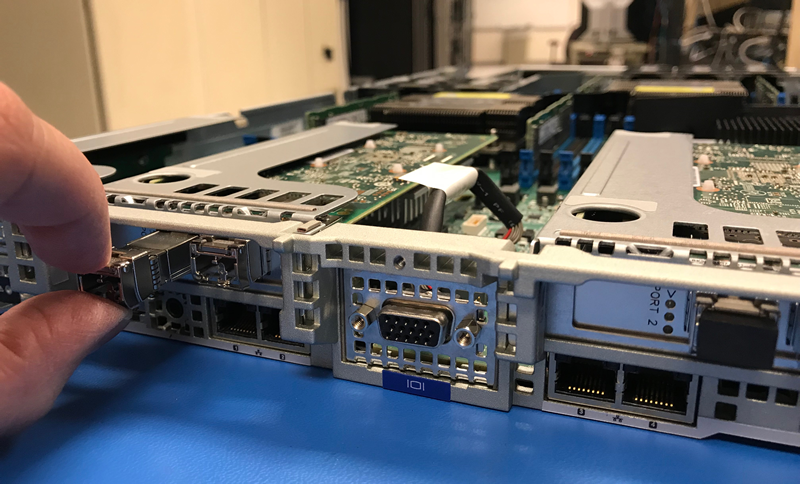
- Disconnect the cables from interface cards installed in the system:
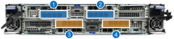
F2100 Slots/Ports (option 1)
If the system contains 32 Gb FC cards, disconnect all FC cables from the FC ports in Controller A and Controller B:
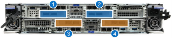
F2100 Slots/Ports (option 2)
If the system contains 100 GbE cards, disconnect the 100 GbE Copper Direct Attach cables from the Ethernet ports on Controller A and Controller B:
- Disconnect your the CAT6A Ethernet cable from the BMC port on the controller, if necessary.
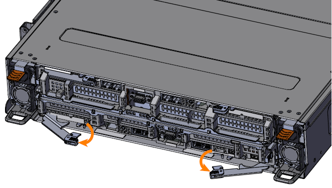
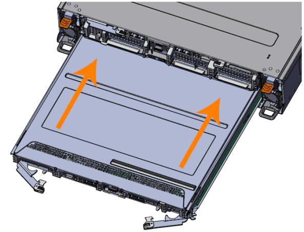
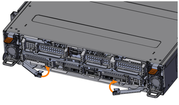
- Unlatch the controller by pulling both of the handles out from the chassis (Controller B shown):
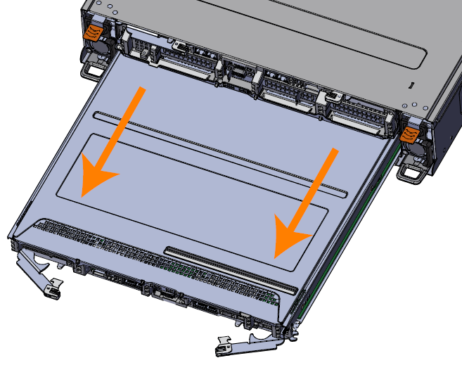
- Remove the controller by grasping the edges of the controller and pulling it clear of the chassis:
- Place the controller on an ESD-protected surface.
- Locate the new controller and unpack it from the box, if necessary.
- Label the replacement controller to distinguish it from the failed controller.
- Place the new controller on an ESD-protected surface.
Note: Install the interface cards in the identical slot location they were in in the failed controller.
Required tools:
- #0 screwdriver
- #2 Phillips screwdriver
- Laptop computer
- Ethernet cable
Before you begin:
Note: This component IS hot-swappable. You DO NOT need to stop all I/O from clients or remove power from both controllers to replace this component.
The chassis is designed to dissipate all electrostatic discharge (ESD) to the chassis base. Ensure that there is sufficient electrical and mechanical connection from the chassis base to the rack rails, and that the rack itself is tied to earth ground. The unit must be grounded in accordance with all local/regional and national electrical codes.
Some components within the F2100 array contain static-sensitive parts. Precautions must be taken to ensure that the system is not exposed to ESD while handling components or servicing the unit. To avoid damaging these parts while performing maintenance procedures, always observe the following precautions:
Keep static-sensitive parts in their original shipping containers until ready for installation.
Do not place static-sensitive parts on a metal surface. Place them inside their protective shipping bag or on an anti-static mat.
Wear anti-static wrist bands when unpacking and handling the units, and avoid touching connectors and other components.
Dry climates and cold-weather heating environments have lower relative humidity and are more likely to produce static electricity.
- Locate the new controller and unpack it from the box, if necessary.
- Place the new controller on an ESD-protected surface.
- Remove the controller cover from the controller being replaced:
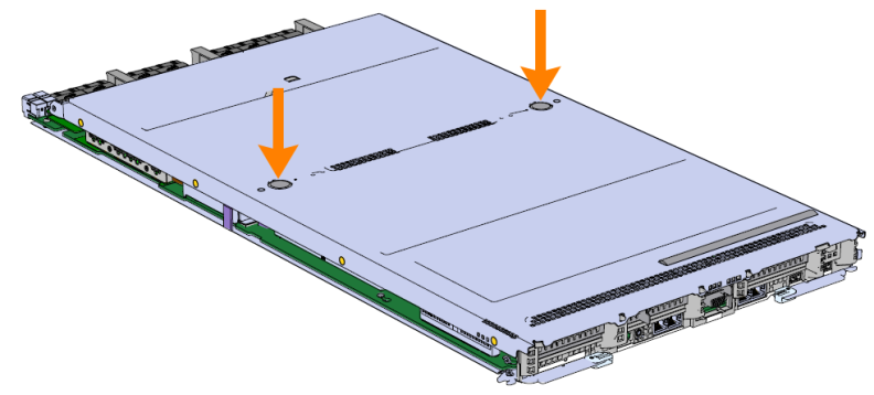
- Unlock the controller cover by pressing the two lock buttons and slide the cover towards the rear of the controller:
- Remove the cover by lifting the cover off of the controller.
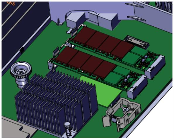
- Remove the internal components needed for the new controller from the controller being replaced:
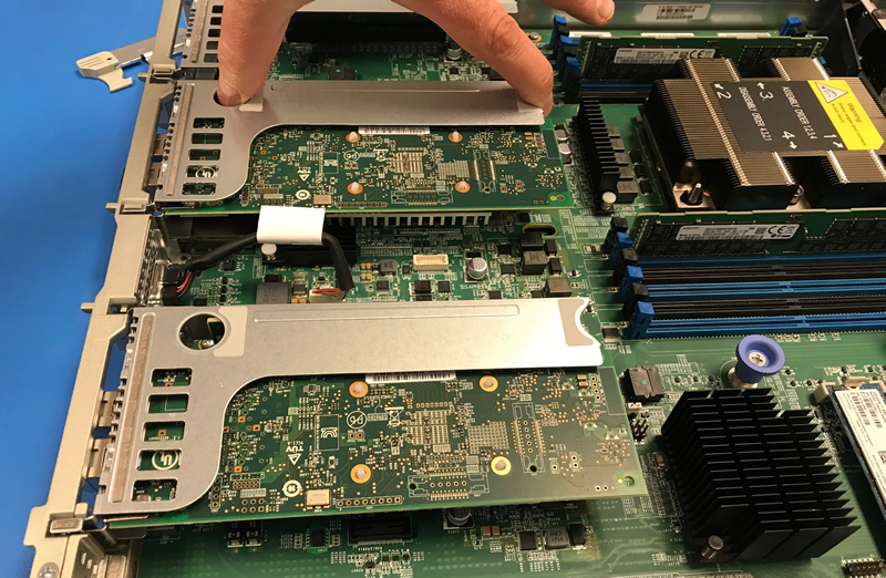
- Locate the PCIe bracket that contains the interface card.
- If used, remove the SFPs from all cards and set them aside:
- Remove the PCIe bracket by carefully pulling up on the sheet metal carrier and lifting it out of the controller:
- Place the PCIe bracket on an ESD-protected surface:
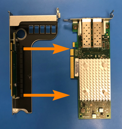
- Detach the interface card from the PCIe bracket by pulling the two components apart
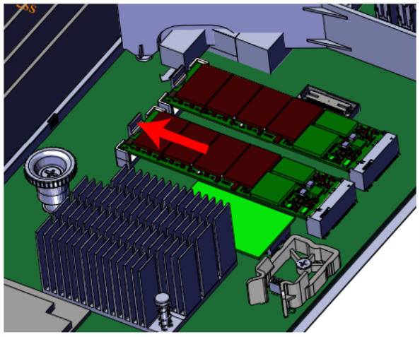
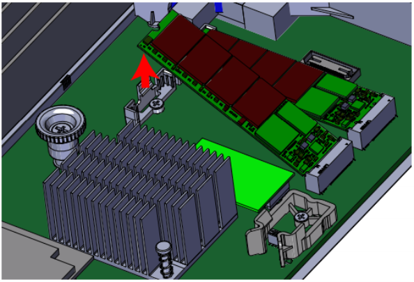
- Press the M.2 boot drive release latch to unseat the drive:
- Remove the drive from the drive slot by pulling it out of the connector.
- Repeat for the other M.2 boot drive.
- Replace the cover on the controller being replaced:
- Align the cover over the controller and slide it towards the front of the controller.
- Verify the lock buttons on the cover have engaged and the cover is secure:
- Remove the cover from the replacement controller:
- Unlock the controller cover by pressing the two lock buttons and slide the cover towards the rear of the controller:
- Remove the cover by lifting the cover off of the controller.
- Install the internal components into the replacement controller:
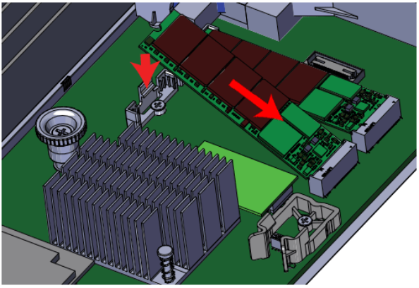
- Slide the card edge of the M.2 boot drive into the connector with even pressure, and the opposite end of the card edge into the release latch:
- Make sure the M.2 boot drive is fully seated in the slot:
- Repeat for the other M.2 boot drive.
- Install the cover on the replacement controller:
- Align the cover over the controller and slide it towards the front of the controller.
- Verify the lock buttons on the cover have engaged and the cover is secure:
Note: If you are removing Controller B, note that this controller is inverted. You must turn the controller over to access the controller cover.

Note: Pay special attention to the slot location for the cards being replaced. They MUST be installed in the same slot location in the replacement controller as they are in the current controller. You may wish to migrate the cards from the old controller and immediately install in to the new controller one card at a time to ensure the cards are installed into the correct slots.
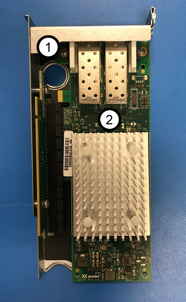
|
Item |
Description |
|
1 |
PCIe bracket |
|
2 |
Interface card (FC card shown in example) |
Pro Tip! Note which M.2 slot the boot drives are located in, so you can replace them into the identical slot on the replacement controller's motherboard.
Note: If you are removing Controller B, note that this controller is inverted. You must turn the controller over to access the controller cover.
Note: Make sure you replace the M.2 boot drives into the identical slot on the replacement controller's motherboard that it was installed in on the faulty controller's motherboard.
Note: Replace the cards in the same slot location they were in the controller being replaced.
(missing or bad snippet)
- Orient the replacement controller by lining up the controller slot in the chassis.
- Insert the controller into the chassis:
- Carefully slide the controller into the slot with both latch handles in the open position until the latch handles begin to engage (Controller B shown):
- Rotate the latch handles into the chassis until the are fully engaged:
Note: Controller B is installed with the top cover facing the top of the chassis. Controller A is inverted and installed with the top cover facing toward the bottom of the chassis.
- From the rear of the chassis, connect the management connections using CAT6A Ethernet cables from the 10 GbE switch to the Port 1 10 GbE port on Controller A and to the Port 1 10 GbE port on Controller B:
- Cable the storage network connections depending on what type of storage network you have:
- If the system contains 100 GbE cards, connect the 100 GbE Copper Direct Attach cables to the Ethernet ports on Controller A and Controller B:
- Connect up to 4 100 GbE Copper Direct Attach cables to the 100 Gb Eth ports in Controller A (top), and connect up to 4 100 GbE Copper Direct Attach cables to the 100 Gb Eth ports in Controller B (bottom) according to the diagram and table below:
- Connect the other end of the 100 Gb Eth Copper Direct Attach cables to a 100 Gb Eth network switch.
- If the system contains 32 Gb FC cards, connect the FC cables to the FC ports in PCIe slot 1 and PCIe slot 3 on Controller A and Controller B:
- Connect up to 8 FC cables to the 32 Gb FC ports in Controller A (top) and up to 8 FC cables to the 32Gb FC ports in Controller B (bottom):
- Connect the other end of the FC cables to a 32 Gb FC switch.
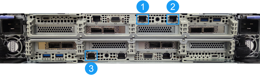
|
Item |
Description |
|
1 |
10 GbE management port on Controller A (connect to a laptop during the initial setup) |
|
2 |
10 GbE data port on Controller A (connect to a network switch where DHCP or static system IP addresses are reachable) |
|
3 |
10 GbE data port on Controller B (connect to a network switch where DHCP or static system IP addresses are reachable) |
Note: Important! Connect the cables to the ports they were originally connected to.
Connect F2100 100 GbE cables
Note: If you are not connecting all 8 100 G Eth ports, connect an even number of ports to the cards in each controller. For simplicity, connect the same ports on Controller A and Controller B. The controllers are installed 180 degrees opposite each other, meaning the slots and the ports are opposite one another.

Note: QSFP optical transceivers need to be used if the switch contains optical ports. QSFP optical transceivers ARE NOT supplied by Quantum.
Connect F2100 FC cables
Note: For maximum performance, connect all 16 FC cables from the FC ports on the system to the FC switch. If you are not connecting all 16 FC ports, connect an even number of ports to the card in each controller. For consistency, connect the same ports on Controller A and Controller B. Connect at least 1 FC cable to one of the ports of each FC card in Controller A (top), and at least 1 FC cable to the same ports of each FC card in Controller B (bottom) for the system to function properly. You must connect a minimum of 2 FC connections for both controllers (a minimum of 4 FC connections for the system).
The controllers are installed 180 degrees opposite each other, meaning the slots and the ports are opposite one another.

- Use the management IP of both Controller A and B to access the F-Series UI.
- Open the HEALTH page, and make sure the overall system health (item 1 below) status, and the status of all the individual components (item 2 below) are all 100% healthy from both Controller’s UI:
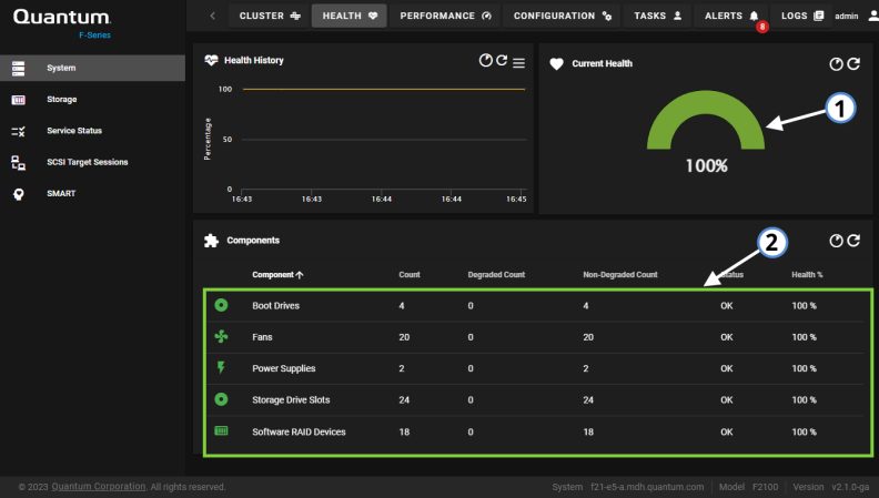
After you've completed this section, the controller replacement is complete.
Required tools
There are no tools required for this component replacement.
Required software/access
For QBSP 2.x and later software, some of the following steps require you to access the QBSP shell.
Before you begin
Note: This component IS hot-swappable. You DO NOT need to stop all I/O from clients or remove power from both controllers to replace this component.
The chassis is designed to dissipate all electrostatic discharge (ESD) to the chassis base. Ensure that there is sufficient electrical and mechanical connection from the chassis base to the rack rails, and that the rack itself is tied to earth ground. The unit must be grounded in accordance with all local/regional and national electrical codes.
Some components within the F2100 array contain static-sensitive parts. Precautions must be taken to ensure that the system is not exposed to ESD while handling components or servicing the unit. To avoid damaging these parts while performing maintenance procedures, always observe the following precautions:
Keep static-sensitive parts in their original shipping containers until ready for installation.
Do not place static-sensitive parts on a metal surface. Place them inside their protective shipping bag or on an anti-static mat.
Wear anti-static wrist bands when unpacking and handling the units, and avoid touching connectors and other components.
Dry climates and cold-weather heating environments have lower relative humidity and are more likely to produce static electricity.
- For systems configured using the qstorage commands in the Appliance Controller (which includes all systems that currently are, or were previously using F-Series 1.x software), you will use commands in the Appliance Controller software on a host system (for example: Xcellis Workflow Director) for this procedure.
- Replace a degraded data drive ONLY with an SSD data drive of the same capacity.
- 3.84 TB
- 7.68 TB
- 15.36 TB
- 30.72 TB
Data drive capacities
The F2100 contains 24 NVMe SSD data drives, with different storage capacities.
Capacity options:
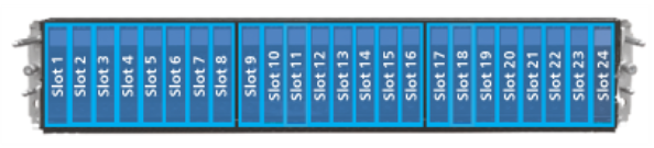
Drive slots are accessible on the front of the F2100 and are numbered 1 through 24 going from left to right:
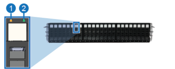
A degraded data drive displays either a solid or blinking illuminated amber LED:
|
Item |
LED |
Action |
|
1 |
Drive Fault LED |
Amber (solid or blinking): Degraded drive reported. Replace the drive. |
|
2 |
Drive Link/Active |
Off: No drive present Green: Drive present Green (Blinking): Drive active |
- Open an SSH session using the management IP address or hostname of the controller using a Terminal/PuTTY client. Connect using a console session on a client that supports ssh (for example, PuTTY on Windows systems, the Windows command line on Windows 10 or later, or the Terminal on MacOS systems).
Use the admin user name and the password for the admin account on the system.
Example (macOS Terminal, Linux or Unix command line, or Windows 10 command prompt):
#ssh admin@(IP or hostname)
- The first time you log into the CLI, you will need to enter "
yes" to accept the ECDSA security key for this system connection when prompted: - Enter the password for the
adminaccount:
The authenticity of host '10.65.184.225.mycompany.com' can't be established.
ECDSA key fingerprint is SHA256:HDCZP/C3ZrIFWONrbl/9s/KCR8g/WXrOXe0V9qbiLbM.
Are you sure you want to continue connecting (yes/no)? yes
You should see a prompt adding the security key to the list of known hosts.
Warning: Permanently added '10.65.184.225' (ECDSA) to the list of known hosts.
admin@(IP or hostname)'s password:
The CLI prompt for the system you are connected to displays.
Last login: Thu Mar 10 10:07:51 2022 from 10.65.188.109
Last login: Thu Mar 10 10:07:51 2022 from 10.65.188.109
One moment, loading command sets...
Welcome to the QBSP shell! Software version: Quantum CSP 2.4.0-Build89
For available commands and usage, type help.
(IP or hostname)>
- Enter the command to locate the failed data drive:
- Take note of the missing drive from the output to locate the location of the drive in the physical unit. In
the output (in bold red) this is in the first system chassis/enclosure (the RAID chassis) in slot 15 and is the
nvme14drive path on Controller A (Node 1 Path), and thenvme9drive path on Controller B (Node 2 Path).
show_drive
If you have a bad drive it will be missing from both controllers, as in the following example.
Drive ID       Node 1 Path  Node 2 Path  LED    Power  Serial
encl01_slot01  /dev/nvme0   /dev/nvme22  True   True   S6EYNA0R600020
encl01_slot02  /dev/nvme1   /dev/nvme23  False  True   S6EYNA0R600019
encl01_slot03  /dev/nvme2   /dev/nvme21  False  True   S6EYNA0R600017
encl01_slot04  /dev/nvme3   /dev/nvme20  False  True   S6EYNA0R600018
encl01_slot05  /dev/nvme4   /dev/nvme19  False  True   S6EYNA0R600015
encl01_slot06  /dev/nvme5   /dev/nvme18  False  True   S6EYNA0R700201
encl01_slot07  /dev/nvme6   /dev/nvme17  False  True   S6EYNA0R700203
encl01_slot08  /dev/nvme7   /dev/nvme16  False  True   S6EYNA0R600016
encl01_slot09  /dev/nvme8   /dev/nvme14  False  True   S6EYNA0R600013
encl01_slot10  /dev/nvme9   /dev/nvme15  False  True   S6EYNA0R700202
encl01_slot11  /dev/nvme10  /dev/nvme13  False  True   S6EYNA0R600021
encl01_slot12  /dev/nvme11  /dev/nvme12  False  True   S4YPNC0T100725
encl01_slot13  /dev/nvme12  /dev/nvme11  False  True   SDM000061BB2
encl01_slot14  /dev/nvme13  /dev/nvme10  False  True   SDM000060367
encl01_slot15                            False  True   SDM000061B2D
encl01_slot16  /dev/nvme15  /dev/nvme8   False  True   SDM000061C0F
encl01_slot17  /dev/nvme16  /dev/nvme6   False  True   SDM00002BFBA
encl01_slot18  /dev/nvme17  /dev/nvme7   False  True   SDM000061BF8
encl01_slot19  /dev/nvme18  /dev/nvme5   False  True   SDM0000178C3
encl01_slot20  /dev/nvme19  /dev/nvme4   False  True   SDM000061BB4
encl01_slot21  /dev/nvme20  /dev/nvme3   False  True   SDM00005E7E9
encl01_slot22  /dev/nvme21  /dev/nvme2   False  True   SDM000060390
encl01_slot23  /dev/nvme22  /dev/nvme1   False  True   SDM000061B5F
encl01_slot24  /dev/nvme23  /dev/nvme0   False  True   SDM00002CE4D
The example output above shows a system with a missing drive path, indicating the failed data drive.
Once you've identified the faulty data drive:
-
Open the CONFIGURATION > Storage page on the F-Series UI.
-
In the lower portion of the screen, in the RAID Array section, click on the drive slot that corresponds to the faulty data drive:
-
In the top of the drive panel, click the 3 dot drop-down icon:
-
Click Detach Drive:

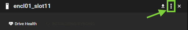
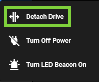
The drive will detach and be ready for replacement.
- Open an SSH session using the management IP address or hostname of the controller using a Terminal/PuTTY client. Connect using a console session on a client that supports ssh (for example, PuTTY on Windows systems, the Windows command line on Windows 10 or later, or the Terminal on MacOS systems).
Use the admin user name and the password for the admin account on the system.
Example (macOS Terminal, Linux or Unix command line, or Windows 10 command prompt):
#ssh admin@(IP or hostname)
- The first time you log into the CLI, you will need to enter "
yes" to accept the ECDSA security key for this system connection when prompted: - Enter the password for the
adminaccount:
The authenticity of host '10.65.184.225.mycompany.com' can't be established.
ECDSA key fingerprint is SHA256:HDCZP/C3ZrIFWONrbl/9s/KCR8g/WXrOXe0V9qbiLbM.
Are you sure you want to continue connecting (yes/no)? yes
You should see a prompt adding the security key to the list of known hosts.
Warning: Permanently added '10.65.184.225' (ECDSA) to the list of known hosts.
admin@(IP or hostname)'s password:
The CLI prompt for the system you are connected to displays.
Last login: Thu Mar 10 10:07:51 2022 from 10.65.188.109
Last login: Thu Mar 10 10:07:51 2022 from 10.65.188.109
One moment, loading command sets...
Welcome to the QBSP shell! Software version: Quantum CSP 2.4.0-Build89
For available commands and usage, type help.
(IP or hostname)>
- Enter:
|
detach_drive auto |
The system identifies the degraded drive and detaches it. It returns the following message if the drive detachment was successful:
|
|
If the drive has lost power or is missing, the system will return the following message:
|
|
- Remove the bezel from the front of the F2100, if needed.
- Obtain the new data drive assembly and open its drive carrier handle by pressing the drive carrier latch release button.
- Orient the data drive assembly so the drive carrier latch release button is on top. Then slowly slide the drive into the open drive slot using the drive carrier release until the drive release engages:
- Seat the drive by pressing the drive carrier handle into the drive carrier until it clicks. This will allow the drive to make the connection with the connector on the drive board without causing damage:
- Repeat for additional drives, if needed.
Note: When seating multiple data drives, wait 15 seconds between drive insertions.
Note: When seating multiple data drives, wait 15 seconds between drive insertions.
-
Open the CONFIGURATION > Storage page on the F-Series UI.
-
In the lower portion of the screen, in the RAID Array section, click on the drive slot that corresponds to the data drive you just replaced:
-
In the top of the drive panel, click the 3 dot drop-down icon:
-
Click Attach Drive:
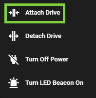
The drive will attach and begin to build and the RAID will begin to synchronize.
- Open an SSH session using the management IP address or hostname of the controller using a Terminal/PuTTY client. Connect using a console session on a client that supports ssh (for example, PuTTY on Windows systems, the Windows command line on Windows 10 or later, or the Terminal on MacOS systems).
Use the admin user name and the password for the admin account on the system.
Example (macOS Terminal, Linux or Unix command line, or Windows 10 command prompt):
#ssh admin@(IP or hostname)
- The first time you log into the CLI, you will need to enter "
yes" to accept the ECDSA security key for this system connection when prompted: - Enter the password for the
adminaccount:
The authenticity of host '10.65.184.225.mycompany.com' can't be established.
ECDSA key fingerprint is SHA256:HDCZP/C3ZrIFWONrbl/9s/KCR8g/WXrOXe0V9qbiLbM.
Are you sure you want to continue connecting (yes/no)? yes
You should see a prompt adding the security key to the list of known hosts.
Warning: Permanently added '10.65.184.225' (ECDSA) to the list of known hosts.
admin@(IP or hostname)'s password:
The CLI prompt for the system you are connected to displays.
Last login: Thu Mar 10 10:07:51 2022 from 10.65.188.109
Last login: Thu Mar 10 10:07:51 2022 from 10.65.188.109
One moment, loading command sets...
Welcome to the QBSP shell! Software version: Quantum CSP 2.4.0-Build89
For available commands and usage, type help.
(IP or hostname)>
- From the QBSP shell, run the command to add the new drive to the system. Enter:
- Run the following command to show the status of the drive recovery operation:
- Replace the bezel on the front of the system.
|
attach_drive auto |
The system identifies the new drive and adds it to the system configuration. It returns the following message if the drive attachment was successful:
|
|
Note: Rebuilds for the arrays occur in parallel.
|
health |
The system provides status of the recovery operation:
|
Rebuild process started:
], "qsa_health": "degraded", "resync": { "finish": "145.4min", "operation": "recovery", "progress": "3.7%", <----- "resynced": 69356160, "speed": "205891K/sec", "total": 1866333184 } } } } }, "model": "F2100", "qsa_health_A": "degraded" |
Note: The system may experience a minor performance impact until the recovery operation completes.
- Open an SSH session using the management IP address or hostname of the controller using a Terminal/PuTTY client. Connect using a console session on a client that supports ssh (for example, PuTTY on Windows systems, the Windows command line on Windows 10 or later, or the Terminal on MacOS systems).
Use the admin user name and the password for the admin account on the system.
Example (macOS Terminal, Linux or Unix command line, or Windows 10 command prompt):
#ssh admin@(IP or hostname)
- The first time you log into the CLI, you will need to enter "
yes" to accept the ECDSA security key for this system connection when prompted: - Enter the password for the
adminaccount:
The authenticity of host '10.65.184.225.mycompany.com' can't be established.
ECDSA key fingerprint is SHA256:HDCZP/C3ZrIFWONrbl/9s/KCR8g/WXrOXe0V9qbiLbM.
Are you sure you want to continue connecting (yes/no)? yes
You should see a prompt adding the security key to the list of known hosts.
Warning: Permanently added '10.65.184.225' (ECDSA) to the list of known hosts.
admin@(IP or hostname)'s password:
The CLI prompt for the system you are connected to displays.
Last login: Thu Mar 10 10:07:51 2022 from 10.65.188.109
Last login: Thu Mar 10 10:07:51 2022 from 10.65.188.109
One moment, loading command sets...
Welcome to the QBSP shell! Software version: Quantum CSP 2.4.0-Build89
For available commands and usage, type help.
(IP or hostname)>
Access the QBSP shell.
- Open an SSH session using the management IP address or hostname of the controller using a Terminal/PuTTY client. Connect using a console session on a client that supports ssh (for example, PuTTY on Windows systems, the Windows command line on Windows 10 or later, or the Terminal on MacOS systems).
Use the admin user name and the password for the admin account on the system.
Example (macOS Terminal, Linux or Unix command line, or Windows 10 command prompt):
#ssh admin@(IP or hostname)
- The first time you log into the CLI, you will need to enter "
yes" to accept the ECDSA security key for this system connection when prompted: - Enter the password for the
adminaccount:
The authenticity of host '10.65.184.225.mycompany.com' can't be established.
ECDSA key fingerprint is SHA256:HDCZP/C3ZrIFWONrbl/9s/KCR8g/WXrOXe0V9qbiLbM.
Are you sure you want to continue connecting (yes/no)? yes
You should see a prompt adding the security key to the list of known hosts.
Warning: Permanently added '10.65.184.225' (ECDSA) to the list of known hosts.
admin@(IP or hostname)'s password:
The CLI prompt for the system you are connected to displays.
Last login: Thu Mar 10 10:07:51 2022 from 10.65.188.109
Last login: Thu Mar 10 10:07:51 2022 from 10.65.188.109
One moment, loading command sets...
Welcome to the QBSP shell! Software version: Quantum CSP 2.4.0-Build89
For available commands and usage, type help.
(IP or hostname)>
- From the QBSP shell, run the command to clear the drive cache. Enter:
- Enter the command to locate the data drive:
- Locate the drive (resolve this for the first drive before attempting to resolve for other drives) in the correct Controller. Notice in the output (in bold red) this is in the first system chassis/enclosure in slot 15 and is the nvme4 device, but is missing from Controller B (in the Node 2 Path column).
-
Remove the missing drive from the chassis:
- Remove the bezel from the front of the F2100, if needed.
-
Insert the drive slowly and make sure it is fully seated:
Note: When seating multiple data drives, wait 15 seconds between drive insertions.
- Obtain the new data drive assembly and open its drive carrier handle by pressing the drive carrier latch release button.
- Orient the data drive assembly so the drive carrier latch release button is on top. Then slowly slide the drive into the open drive slot using the drive carrier release until the drive release engages:
- Seat the drive by pressing the drive carrier handle into the drive carrier until it clicks. This will allow the drive to make the connection with the connector on the drive board without causing damage:
- Repeat for additional drives, if needed.
Note: When seating multiple data drives, wait 15 seconds between drive insertions.
Note: When seating multiple data drives, wait 15 seconds between drive insertions.
-
Review the output of the
show_drivecommand, as explained above. - Stop I/O to all connected clients.
- Cycle chassis power for both controllers. Enter:
- Wait for the system to reboot. After the system reboots, log back into the command line, and re-run Step 6 through Step 8 and verify the drive paths are all shown. At this point. there are two outcomes of the 12-drive pack upgrade:
-
If all drive paths are shown for Controller A and Controller B the 12-drive pack upgrade was successful. Restore I/O to all previously-connected clients.
-
If a chassis power cycle still does not resolve the issue, contact Quantum support for further instructions.
If you do not see a missing drive from either controller, as in Example Output # 1, you are done.
Drive ID       Node 1 Path  Node 2 Path  LED    Power  Serial           State
encl01_slot01  /dev/nvme23  /dev/nvme10  False  True   S6ULNA0Y102359   active
encl01_slot02  /dev/nvme22  /dev/nvme9   False  True   S6ULNA0Y102341   active
encl01_slot03  /dev/nvme21  /dev/nvme8   False  True   S6ULNA0Y102352   active
encl01_slot04  /dev/nvme20  /dev/nvme7   False  True   S6ULNA0Y102377   active
encl01_slot05  /dev/nvme18  /dev/nvme5   False  True   S6ULNA0Y102269   active
encl01_slot06  /dev/nvme17  /dev/nvme4   False  True   S6ULNA0Y105951   active
encl01_slot07  /dev/nvme25  /dev/nvme17  False  True   S6ULNA0Y102357   active
encl01_slot08  /dev/nvme24  /dev/nvme16  False  True   S6ULNA0Y102361   active
encl01_slot09  /dev/nvme11  /dev/nvme14  False  True   S6ULNA0Y106058   active
encl01_slot10  /dev/nvme12  /dev/nvme6   False  True   S6ULNA0Y102360   active
encl01_slot11  /dev/nvme13  /dev/nvme2   False  True   S6ULNA0Y102378   active
encl01_slot12  /dev/nvme19  /dev/nvme1   False  True   S6ULNA0Y102379   active
encl01_slot13  /dev/nvme2   /dev/nvme15  False  True   S6ULNA0Y106064   active
encl01_slot14  /dev/nvme3   /dev/nvme13  False  True   S6ULNA0Y106089   active
encl01_slot15  /dev/nvme4   /dev/nvme12  False  True   S6ULNA0Y105937   active
encl01_slot16  /dev/nvme14  /dev/nvme11  False  True   S6ULNA0Y106066   active
encl01_slot17  /dev/nvme15  /dev/nvme21  False  True   S6ULNA0Y106067   active
encl01_slot18  /dev/nvme16  /dev/nvme24  False  True   S6ULNA0Y106065   active
encl01_slot19  /dev/nvme5   /dev/nvme18  False  True   S6ULNA0Y106070   active
encl01_slot20  /dev/nvme6   /dev/nvme19  False  True   S6ULNA0Y106068   active
encl01_slot21  /dev/nvme7   /dev/nvme20  False  True   S6ULNA0Y106071   active
encl01_slot22  /dev/nvme8   /dev/nvme22  False  True   S6ULNA0Y106069   active
encl01_slot23  /dev/nvme9   /dev/nvme23  False  True   S6ULNA0Y106007   active
encl01_slot24  /dev/nvme10  /dev/nvme25  False  True   S6ULNA0Y105850   active
Drive ID       Node 1 Path  Node 2 Path  LED    Power  Serial           State
encl01_slot01  /dev/nvme23  /dev/nvme10  False  True   S6ULNA0Y102359   active
encl01_slot02  /dev/nvme22  /dev/nvme9   False  True   S6ULNA0Y102341   active
encl01_slot03  /dev/nvme21  /dev/nvme8   False  True   S6ULNA0Y102352   active
encl01_slot04  /dev/nvme20  /dev/nvme7   False  True   S6ULNA0Y102377   active
encl01_slot05  /dev/nvme18  /dev/nvme5   False  True   S6ULNA0Y102269   active
encl01_slot06  /dev/nvme17  /dev/nvme4   False  True   S6ULNA0Y105951   active
encl01_slot07  /dev/nvme25  /dev/nvme17  False  True   S6ULNA0Y102357   active
encl01_slot08  /dev/nvme24  /dev/nvme16  False  True   S6ULNA0Y102361   active
encl01_slot09  /dev/nvme11  /dev/nvme14  False  True   S6ULNA0Y106058   active
encl01_slot10  /dev/nvme12  /dev/nvme6   False  True   S6ULNA0Y102360   active
encl01_slot11  /dev/nvme13  /dev/nvme2   False  True   S6ULNA0Y102378   active
encl01_slot12  /dev/nvme19  /dev/nvme1   False  True   S6ULNA0Y102379   active
encl01_slot13  /dev/nvme2   /dev/nvme15  False  True   S6ULNA0Y106064   active
encl01_slot14  /dev/nvme3   /dev/nvme13  False  True   S6ULNA0Y106089   active
encl01_slot15  /dev/nvme4                False  True   S6ULNA0Y105937   active
encl01_slot16  /dev/nvme14  /dev/nvme11  False  True   S6ULNA0Y106066   active
encl01_slot17  /dev/nvme15  /dev/nvme21  False  True   S6ULNA0Y106067   active
encl01_slot18  /dev/nvme16  /dev/nvme24  False  True   S6ULNA0Y106065   active
encl01_slot19  /dev/nvme5   /dev/nvme18  False  True   S6ULNA0Y106070   active
encl01_slot20  /dev/nvme6   /dev/nvme19  False  True   S6ULNA0Y106068   active
encl01_slot21  /dev/nvme7   /dev/nvme20  False  True   S6ULNA0Y106071   active
encl01_slot22  /dev/nvme8   /dev/nvme22  False  True   S6ULNA0Y106069   active
encl01_slot23  /dev/nvme9   /dev/nvme23  False  True   S6ULNA0Y106007   active
encl01_slot24  /dev/nvme10  /dev/nvme25  False  True   S6ULNA0Y105850   active
If you do see one or more missing drive paths from either controller, as in Example Output #2, you will need to resolve this or the system will not function properly. Continue with the following steps:
If drive paths are still missing from either controller (Node 1 or 2 Path), repeat Step 4 through Step 8 to re-seat those additional drives one at a time, and review if there are any drive paths still missing. Repeat as necessary. After 5 attempts, if the device paths are still not all present, do the following:
After you've completed this section, the data drive replacement is complete.
Required tools
There are no tools required for this component replacement.
Before you begin
Note: This component IS hot-swappable. You DO NOT need to stop all I/O from clients or remove power from both controllers to replace this component.
The chassis is designed to dissipate all electrostatic discharge (ESD) to the chassis base. Ensure that there is sufficient electrical and mechanical connection from the chassis base to the rack rails, and that the rack itself is tied to earth ground. The unit must be grounded in accordance with all local/regional and national electrical codes.
Some components within the F2100 array contain static-sensitive parts. Precautions must be taken to ensure that the system is not exposed to ESD while handling components or servicing the unit. To avoid damaging these parts while performing maintenance procedures, always observe the following precautions:
Keep static-sensitive parts in their original shipping containers until ready for installation.
Do not place static-sensitive parts on a metal surface. Place them inside their protective shipping bag or on an anti-static mat.
Wear anti-static wrist bands when unpacking and handling the units, and avoid touching connectors and other components.
Dry climates and cold-weather heating environments have lower relative humidity and are more likely to produce static electricity.
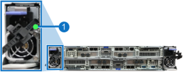
At the rear of the F2100, locate the failed PSU by identifying the PSU with the illuminated amber PSU Fault LED:

|
Item |
LED |
Action |
|
1 |
PSU Fault LED |
Amber (solid): Fault, failure, or AC disconnection on PSU |
| 1. | From the rear of the chassis, disconnect the power cord connected to the failed PSU. |
| a. | Remove the power cord by pulling firmly, but do not jerk it out of the unit. |
| 2. | Remove the PSU from the chassis. |
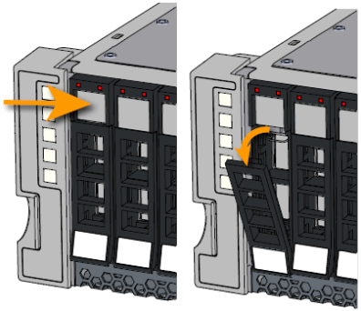
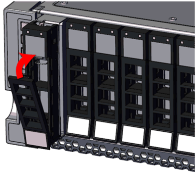
| a. | Unlock the PSU by pressing down on the PSU release latch: |
![]()
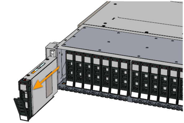
| b. | Remove the PSU by pulling on the PSU handle until it is clear of the PSU bay: |
Note: Do not pull on the gray PIB canister tab. The PIB canister should not be removed from the chassis unless it has been identified as a failed part.
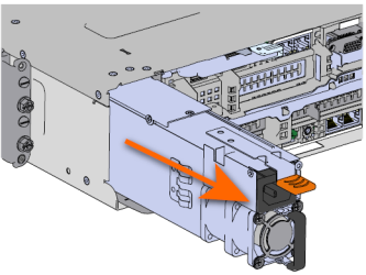
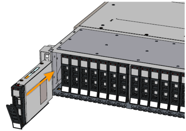
| 1. | Install the PSU into the chassis. |
| a. | Orient the PSU so the PSU release latch is on top and the fan is on the bottom. |
| b. | Slide the PSU into the slot until it seats properly into the chassis: |

| c. | Plug the power cable into the receptacle at the back of the PSU. |
| 2. | Verify the PSU is functional by identifying the PSU Fault LED is no longer indicating a fault. This is indicated by the PSU Fault LED illuminated green: |
|
Item |
LED |
Action |
|
1 |
PSU Fault LED |
Green solid: Powered on, DC output OK |
After you've completed this section, the PSU replacement is complete.
Required tools
There are no tools required for this component replacement.
Before you begin
Note: This component IS hot-swappable. You DO NOT need to stop all I/O from clients or remove power from both controllers to replace this component.
The chassis is designed to dissipate all electrostatic discharge (ESD) to the chassis base. Ensure that there is sufficient electrical and mechanical connection from the chassis base to the rack rails, and that the rack itself is tied to earth ground. The unit must be grounded in accordance with all local/regional and national electrical codes.
Some components within the F2100 array contain static-sensitive parts. Precautions must be taken to ensure that the system is not exposed to ESD while handling components or servicing the unit. To avoid damaging these parts while performing maintenance procedures, always observe the following precautions:
Keep static-sensitive parts in their original shipping containers until ready for installation.
Do not place static-sensitive parts on a metal surface. Place them inside their protective shipping bag or on an anti-static mat.
Wear anti-static wrist bands when unpacking and handling the units, and avoid touching connectors and other components.
Dry climates and cold-weather heating environments have lower relative humidity and are more likely to produce static electricity.
| 1. | After identifying the failed PIB canister, disconnect the power cord from the PSU that is connected to the PIB: |
| d. | Remove the power cord by pulling firmly, but do not jerk it out of the unit. |
| 2. | Remove the PSU from the chassis. |
| a. | Unlock the PSU by pressing down on the PSU release latch: |
![]()
| b. | Remove the PSU by pulling on the PSU handle until it is clear of the PSU bay: |

| 3. | Remove the PIB Canister: |
| a. | Locate the gray tab just below the location of the removed PSU. |
| b. | Grasp the gray tab firmly and carefully pull the PIB Canister until the card edge comes out of the midplane: |
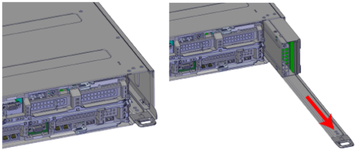
| c. | Pull the PIB canister out from the chassis. |
| 1. | Line up the PIB canister with the chassis PIB canister guide. |
| 2. | Slowly slide the PIB Canister into the chassis until the card edge touches the midplane connector: |
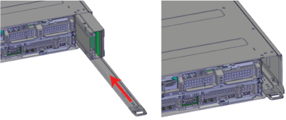
| 3. | Press the PIB canister into the midplane connector. |
| 4. | Verify that the PIB canister is seated firmly. |
| 5. | Install the PSU into the chassis: |
| a. | Orient the PSU so the PSU release latch is on top and the fan is on the bottom. |
| b. | Slide the PSU into the slot until it seats properly into the chassis: |
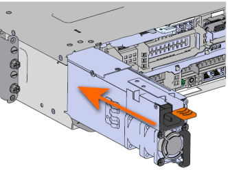
| c. | Plug the power cable into the receptacle at the back of the PSU. |
After you've completed this section, the PIB Canister replacement is complete.