Site Planning
The Quantum ActiveScale Z200™ is the next generation all flash hardware platform for ActiveScale object storage. It provides a simplified deployment by converging the system and storage node functions into a single server and has virtually unlimited scaling capabilities.
The Z200 is delivered on one or more pallets and is installed on-site. This section describes the space required for unpacking and installation.
Use the following guidelines regarding build space during installation:
-
Plan an unpacking and installation sequence if there is not enough space to unpack and store all of the components at once.
-
While installing system components, a minimum of 48 in (1220 mm) of space is required at the front of the rack. This allows for the largest system component to be installed by two people. If space is not available in the location where the system will operate, consider building the system outside the operational location and moving it into location when finished.
-
If the system will be moved after being built, measure the size of the rack and check the walking path to ensure that the rack will fit as it moves through the deployment site.
Note: Before moving the system, verify that the rack can support the dynamic load of the system weight during movement.
During the receiving process, the system will need to be moved through the facility until it reaches the data center or computer room where it will be installed. This section describes the considerations that the installation team should make before receiving the system and moving it through the facility.
Walking paths must be clear of obstructions and wide enough to allow passage of the packaged system to the location where it will be unpacked. The following is a list of obstructions to consider when conducting a walking path inspection:
| Cables | Consider removing cables, including ramped cable covers, from the walking path before moving the pallet. Leaving the cables in place creates a safety hazard for the installation team and can damage the cables. |
| Lift Locations | There may be locations along the walking path where the system must be lifted in order to proceed. Make sure that lift equipment is available at this location on the day of the delivery. |
| Elevators | Ensure that any elevators that will be required to lift the equipment to the data center/computer room are rated to carry the full load of the system plus passengers. |
| Security | Make sure that all site security requirements adhered to and that all personnel are made aware of the parameters under which they must work. |
|
Parameter |
Specification |
|---|---|
| Operating Temperature |
10°C ~ 35°C (50°F ~ 95°F) |
| Non-operating Temperature |
-40°C to 60°C (-40°F to 140°F) |
| Operating Relative Humidity |
8% to 90% (non-condensing) |
| Non-operating Relative Humidity |
5% to 95% (non-condensing) |
The front and rear of the system must be clear of any materials that could block or disrupt system airflow. Disruption of airflow can cause performance issues or system damage due to overheating.
Use the following guidelines to ensure proper system airflow:
-
The airflow in and out of the equipment must not be restricted.
-
Controlled air conditioners that are functional and can sufficiently maintain specified system operating temperatures should be located in the facility where the system will be installed.
-
If rack doors will be used, ensure that the solution used with the system does not prevent airflow from the cold aisle from entering the system freely.
Z200 Chassis - Front and Rear
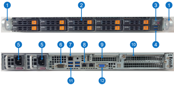
| Item | Description |
|---|---|
| 1 |
Front handles WARNING: Do not pick up the node with the front handles. They are designed to pull the system from a rack only. |
| 2 | (10) 2.5" NVMe drive (15.36 TB, 30.72 TB, 61.44 TB SSD) |
| 3 | Control panel |
| 4 | (2) USB 3.0 storage ports |
| 5 |
(2) 750W Hot-swappable redundant, load-sharing AC power supply unit (PSU)
|
| 6 | COM port |
| 7 | RJ-45 100/1000BASE-T IPMI port |
| 8 | (2) RJ-45 100/1000BASE-T management port (left port # 1 and right port # 2) |
| 9 | Expansion card slot for low-profile, half length (LPHL) expansion (add-on) card |
| 10 | (2) 2 x 10/25 GbE Ethernet ports (SFP+) |
| 11 | (4) USB 3.0 storage ports |
| 12 | VGA port |
Control Panel
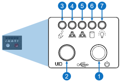
| Item | LED/Button | Description |
|---|---|---|
| 1 | Power Buttom |
Use the main power switch to apply or remove power to the node. If you turn off the system power with this button, then the process removes the main power but keeps standby power supplied to the node.
Caution: You must unplug the AC power cord before you service the node. |
| 2 | Unit identifier (UID) button |
Press the button to illuminate an LED on both the front and rear of the node for easy system location in a rack configuration. The LED remains on until the button is pushed a second time. Blue: Solid, unit identified None: Off, UID is off Note: A UID button on the rear of the node serves the same function. |
| 3 | Universal information |
|
| 4 | 10/100/1000BASE-T RJ-45 port |
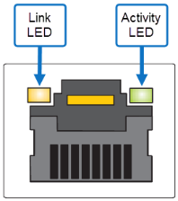
Indicates network activity on the management port # 1. The physical port LEDs represent the following:
Link LED
Activity LED
|
| 5 | 10/100/1000BASE-T RJ-45 port |
Indicates network activity on the management port # 2. The physical port LEDs represent the following:
Link LED
Activity LED
|
| 6 | When flashing, indicates drive activity. | |
| 7 | Indicates power is supplied to the system's power supply units; this LED illuminates when the system is operating normally. |
1U12 Z200 Chassis Specifications
|
Parameter |
Specification |
|---|---|
| Chassis |
1U Rackmount W x H x D: 17.2" (437 mm) x 1.7" (43 mm) x 23.5" (597 mm) 60 lbs (27.2 kg) |
| Drives |
|
| Capacity |
Minimum: 460.8 TB Maximum: Unlimited |
| Cooling | 4 cm cooling fans (6) |
| Memory | DDR4,32 GB,RDIMM,3200 MT,2Rx4 (8) |
| Motherboard | H12SSW-NTR: proprietary form factor 13.4" x 12.29" (340mm x 312mm) |
| Power Supply | 750W redundant power supply (2) |
| Processor | Single AMD EPYC™ 7002 Series Processor |
Each Z200 chassis contains two 750 watt power supply units (PSU) for redundancy.
|
Parameter |
Specification |
|---|---|
| Power Cable | C13/C14 (2) |
| AC Input Voltages | 100-240 VAC |
| Rated Current | 8.5 - 6.0 A |
| Rated Input Frequency | 50-60 Hz |
| Rated Output Power | 750W |
| Rated Output Voltages | +3.3V (25A), +5V (25A), +12V (700W: 58A at 100V-140V, 750W: 62A at 180V-240V), -12V (0.6A), +5Vsb (3A) |
The Z200 does not come with its own power distribution unit (PDU). To prevent the potentially negative effects of excessive inrush current on the system, Quantum recommends selecting a PDU that can stagger the start-up sequence of the system components. If a PDU that cannot stagger the start-up sequence is used, ensure that the PDU is rated to support the inrush current caused by a simultaneous start-up.
The Z200 is installed into a customer-supplied rack. Use the guidelines in this section to choose an appropriate rack mounting solution.
Note: The absolute minimum depth requirement for the Z200 is 42.12 in (1070 mm). However, Quantum recommends selecting a rack with a minimum depth of 48 in (1200 mm) to allow for proper PDU installation and cable routing.
Use the following additional guidelines when choosing a rack mounting solution for the Z200:
| System Dimensions |
Select a rack mounting solution that has the appropriate depth to accommodate the following:
|
| Z200 Rail Kits |
|
| System Weight |
Select a rack mounting solution that can withstand the following:
|
| Cable Management | The system is designed so the cables are wired at the back of the system. Ensure that the system cabling can be routed safely and efficiently through the selected route. |
| Grounding | Ensure that both the electrical components used to power the system and the rack itself can be grounded safely. |
| Electromagnetic Emissions | FCC Class A, EN 55032 Class A, EN 61000-3-2/3-3, CISPR 32 Class A |
| Electromagnetic Immunity | EN 55024/CISPR 24, (EN 61000-4-2, EN 61000-4-3, EN 61000-4-4, EN 61000-4-5, EN 61000-4-6, EN 61000-4-8, EN 61000-4-11), CNS14336-1, CNS13438, GB4943.1-2011, GB9254-2008(Class A) and GB17625.1-2012 |
| Safety | CSA/EN/IEC/UL 60950-1 Compliant, UL or CSA Listed (USA and Canada), CE Marking (Europe) |
| Other | VCCI-CISPR 32 and AS/NZS CISPR 32 |
|
Environmental |
Directive 2011/65/EU and Delegated Directive (EU) 2015/863 and Directive 2012/19/EU |
Note: Mounting a PDU or other equipment vertically in the rack can hinder the ability to service components.
To properly install and service system components, the Quantum recommends the following space at the front and rear of the system.
Table 1: Space requirement specifications
|
Specification |
Value |
|
Minimum front of rack space |
48 in (1220 mm) |
|
Minimum rear of rack space |
22 in (560 mm) |
Figure 1: Minimum servicing space required

The Z200 shipment includes a minimum of 1 1U12 base system node and 2 1U12 server expansion nodes shipped on a pallet.
| Base System Node | Server Expansion Node 1 | Server Expansion Node 2 | |
|---|---|---|---|
| Box Dimensions |
31 x 24 x 7 (inches) 78.7 x 61.0 x 17.8 (cm) |
31 x 24 x 7 (inches) 78.7 x 61.0 x 17.8 (cm) |
31 x 24 x 7 (inches) 78.7 x 61.0 x 17.8 (cm) |
| Box Weight |
40 lbs 18.1 kg |
40 lbs 18.1 kg |
40 lbs 18.1 kg |
| Pallet Weight |
216 lbs (includes switch bundles in overpack box). 100 kg |
||
Each base system node carton contains the following:
| Quantity | Item |
|---|---|
| 1 | 1U12 Server Chassis (drives installed) |
| 1 | Accessory Kit (includes 2 C13/14 13A/250V Power Cables (5ft.), 2 2x25 GbE SFPs, and 2 2x10 GbE SFPs). |
| 1 | Document Kit (inlcudes Getting Started Guide and anti-static wrist strap. |
| 1 | Rail mounting Kit |
| 3 | CAT 6A, RJ45 Cables (7 ft.) |
| 6 | 10/25 GbE SFP28 Direct Attach Cables (3 meters) |
Each server expansion node carton contains the following. The CAT and DAC cables are placed in the Server Expansion Node 1 box.
| Quantity | Item |
|---|---|
| 1 | 1U12 Server Chassis (drives installed) |
| 1 | Accessory Kit (includes 2 C13/14 13A/250V Power Cables (5ft.), 2 2x25 GbE SFPs, and 2 2x10 GbE SFPs). |
| 1 | Rail mounting Kit |
| 3 | CAT 6A, RJ45 Cables (7 ft.) |
| 6 | 10/25 GbE SFP28 Direact Attach Cables (3m) |
The Z200 switch bundle includes 2 packaged switches in a single overpack box.
| Overpack Box | |
|---|---|
| Box Dimensions |
26.5 x 26.5 x 21 (inches) 67.3 x 67.3 x 53.3 (cm) |
| Box Weight |
Overpack Box 66 lbs 30 kg Switch 1 30 lbs 13.6 kg Switch 2 30 lbs 13.6 kg |
Each switch in the overpack box contains the follwing:
| Quantity | Item |
|---|---|
| 1 | 10/25 GbE 48 port switch |
| 1 | Panel filler, vented |
| 1 | Rail kit |
| 2 | C13/14 13A/250V Power Cables (5ft.) |
Two Quantum-supplied (pictured below) or customer-supplied data switches are required to provide the back-end network for the Z200. Additional data switches may be required depending on the size of the deployment.
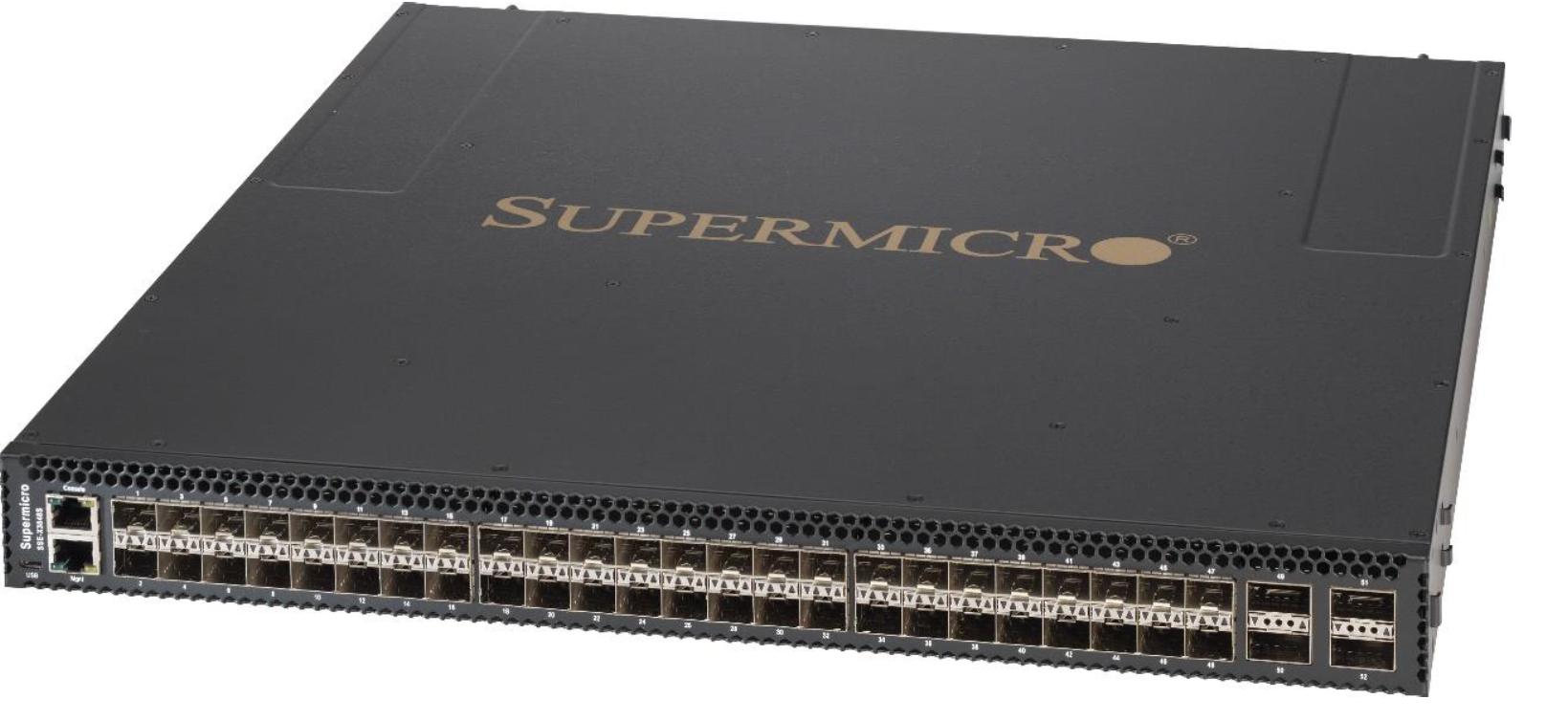

One Quantum-supplied (pictured below) or customer-supplied IPMI switch per rack is required to provide the remote management network for the compute and I/O modules.


This section gives a high-level overview of the requirements and quantities of networking components for Z200 systems, mainly for planning purposes. Note that the Z200 Sizing Tool also reports this output when sizing a system.
The networking setup for a High-Available ActiveScale Z200 system consists of several different networks and networking components. The public traffic to and from the system goes via 2 networks which usually have their own dedicated switch(es). The internal traffic is also handled by 2 dedicated and independent networks, where each network typically has dedicated switches to guarantee High Availability when a switch goes down. One of the internal networks also hosts the IPMI connectivity for all the nodes. These are usually interconnected via a dedicated IPMI switch, which is then connected to one of the internal switches as well..
To accommodate the Z200 internal traffic 10/25 GbE switches are required. 25 GbE is recommended, since 10 GbE will result in lower performance of the ActiveScale Z200 system.
All the internal traffic will be spread across 2 independent networks for HA reasons. Therefore, an even number of 10/25 GbE switches is recommended.
Data Switch Requirements
These data switches need to have the following requirements:
-
Layer-3 switch with full non-blocking backplane, support for static IP routing, 802.1Q (tagged VLANs), port-based VLANs and Telnet/SSH for remote login and management.
-
Each Z200 1U12 node has 4 10/25 GbE network ports. Half of the ports of each node will be used for internal traffic, so we need 2 10/25 GbE ports per node to be connected to the internal data traffic switches. If 2 switches are used for internal connectivity, then 1 of the connections need to go to switch 1 and the one to switch 2. If only a single switch is used (not recommended), then all 2 internal connections need to go to this single switch.
These ports need to support either 10 or 25 GbE (via DAC cables or SFP+/SFP28 optical transceivers).
-
During the ActiveScale software installation, the VM installer will have to be connected to the 1st internal network using a connection that offers a network speed of 1 GbE or better. Therefore, 1 additional switch port should be foreseen in the 1st internal network. This port will only be used during the ActiveScale software installation and can be repurposed when the install is complete.
-
When there will be more than 2 internal data traffic switches, at least 2 ports per switch need to be configured as scale-out ports (to provide interconnectivity between the switches).
-
These scale-out ports need to support either 40/100 GbE (recommended, via DAC cables or QSFP/QSFP28 optical transceivers), or 10/25 GbE (via DAC cables or SFP+/SFP28 optical transceivers).
-
For performance reasons it might be required to have more than 2 ports per switch configured as scale-out ports.
-
-
For 3-Geo deployments at least 1 port per switch needs to be used for inter-geo connectivity.
-
These inter-geo connectivity ports need to support either 40/100 GbE (recommended; via DAC cables or QSFP/QSFP28 optical transceivers), or 10/25 GbE (via DAC cables or SFP+/SFP28 optical transceivers).
-
For performance reasons it might be required to have more than 1 port per switch configured as inter-geo connectivity ports.
-
IPMI Switch Requirements
To accommodate the Z200 internal IPMI traffic, RJ45-based 1GbE switches are required. 1GbE is recommended, but other network speeds should also work fine.
These IPMI switches need to have the following requirements:
-
Software features to support Layer2/Layer-3 networking including VLAN, Telnet/SSH for remote login and management, …
-
The system needs a total of 1 RJ45 ports per base system node on the IPMI switches.
-
The system needs a total of 1 RJ45 ports per server expansion node on the IPMI switches.
-
Each IPMI switch needs 1 port for connectivity to the internal data switches of the first internal data traffic network.
To accommodate the public traffic 10/25 GbE switches are required. 25 GbE is recommended, since 10 GbE will result in lower performance of the system. If NIC bonding will be used on the public interfaces, then these switches need to support Dynamic link aggregation (802.3ad, LACP).
The public traffic can be spread across multiple switches for HA reasons, or only a single switch can be used. The same switches as for the internal traffic can be used, or different switches can be used.
These switches need to have the following requirements:
-
The system needs a total of 2 10/25 GbE ports per Z200 node on the public switches. These ports need to support either 10/25 GbE (via DAC cables or SFP+/SFP28 optical transceivers).
-
The ports on the switch connected to the ActiveScale public interfaces should be able to receive UNTAGGED traffic, because ActiveScale public interfaces can’t be configured to tag traffic for a certain VLAN. Therefore, these switch ports should be set in access mode (not trunk):
switchport mode access
The table below contains the number of required switch ports for some common Z200 configurations:
Note: The extra port in Network 1 is the uplink port to the IPMI switch (if a separate IPMI switch is used).
| Z200 Configuration | Switch ports for Internal Network 1 | IPMI Ports (Internal Network 1 | Switch ports for Internal Network 2 | Switch ports for public traffic |
|---|---|---|---|---|
| 3 x Z200 1U12 nodes | 4 x 10/25 GbE |
3 x 1 GbE |
3 x 10/25 GbE | 6 x 10/25 GbE |
| 6 x Z200 1U12 nodes | 7 x 10/25 GbE |
6 x 1 GbE . |
6 x 10/25 GbE | 12 x 10/25 GbE |
| 60 x Z200 1U12 nodes | 37 x 10/25 GbE |
36 x 1 GbE |
36 x 10/25 GbE | Up to 72 x 10/25 GbE |
A Z200 system minimum configuration consists of 1 1U12 base system node and 2 1U12 server expansion nodes.
Figure 2: Z200 Minimum Configuration
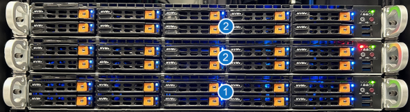
| Item | Description |
|---|---|
| 1 | Z200 Base System Node (1) |
| 2 | Z200 Server Expansion Node (2) |