Site Planning
X200 Hardware Overview
The Quantum ActiveScale X200™ is the next generation hardware platform for ActiveScale object storage. It provides a simplified deployment by converging the system and storage node functions into a single server and has virtually unlimited scaling capabilities.
A base configuration consists of the following:
-
1 4U90 Base System Node. This chassis contains the following:
-
2 compute modules.
-
Drive capacity of 30, 60, or 90 16 TB, 18 TB, 22 TB, or 24 TB HDD's per chassis.
-
-
1 4U90 Server Expansion Node. This chassis contains the following:
-
Drive capacity of 30, 60, or 90 16 TB, 18 TB, 22 TB, or 24 TB HDD's per chassis.
-
-
2 X200 16 TB, 18 TB, 22 TB, or 24 TB HDD bundles.
You can add additional 4U90 JBODs for virtually unlimited capacity. The X200 can also be used to scale out capacity of an existing X100 deployment.
Note: The X200 can be used to scale the capacity of an X100 system but can not use the computing performance of the X200 twin servers.
The X200 base configuration installation also requires the following components, which may be customer-supplied or optionally purchased from Quantum:
-
A supported rack
-
Two PDU's per rack
-
Two data switches for a base system configuration (additional data switches may be required depending on the size of the deployment)
-
One IPMI switch per rack.
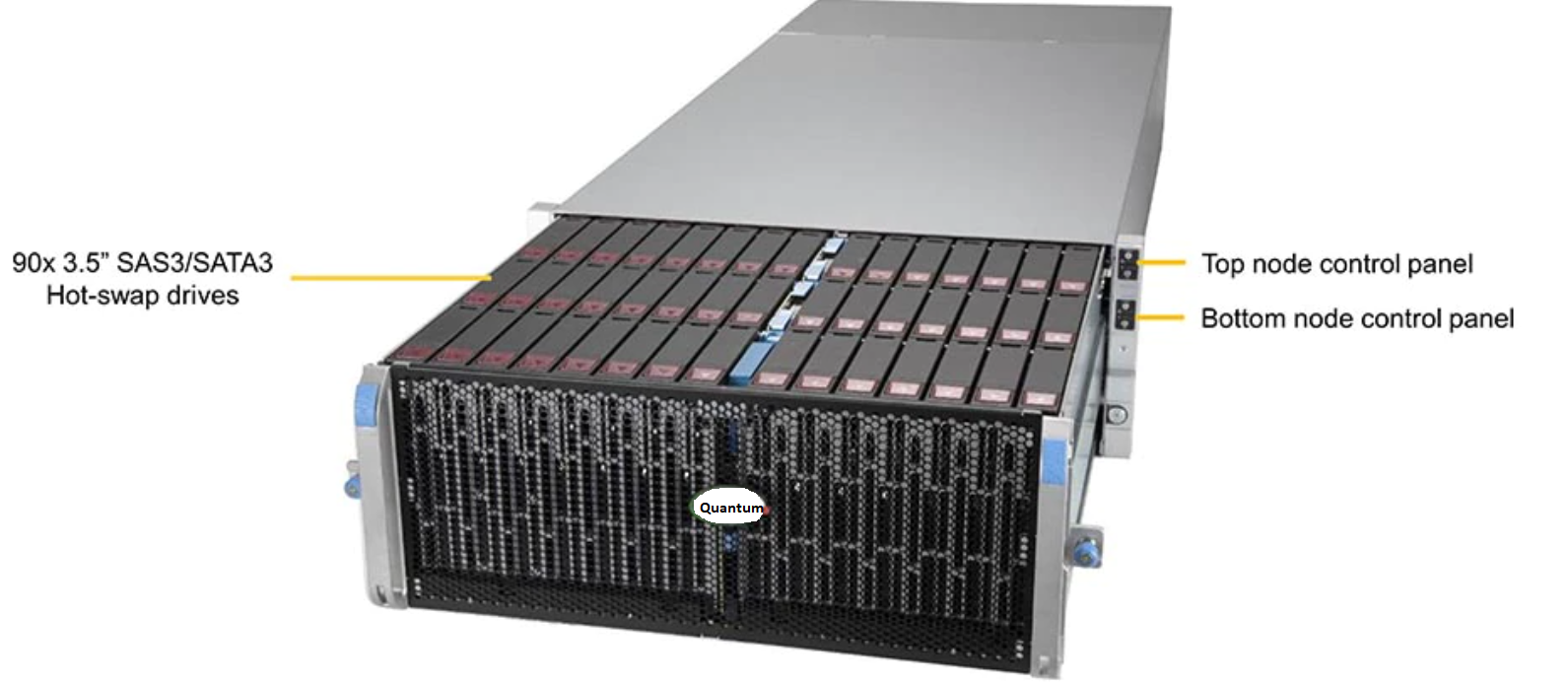
The 4U90 Twin Base Server contains the drive drawer, compute modules, controls, power supplies, fans, and I/O ports
The front of the 4U90 Base System Node contains the drawer locks, drawer latches, drawer handles, control panel, and the rack locks.
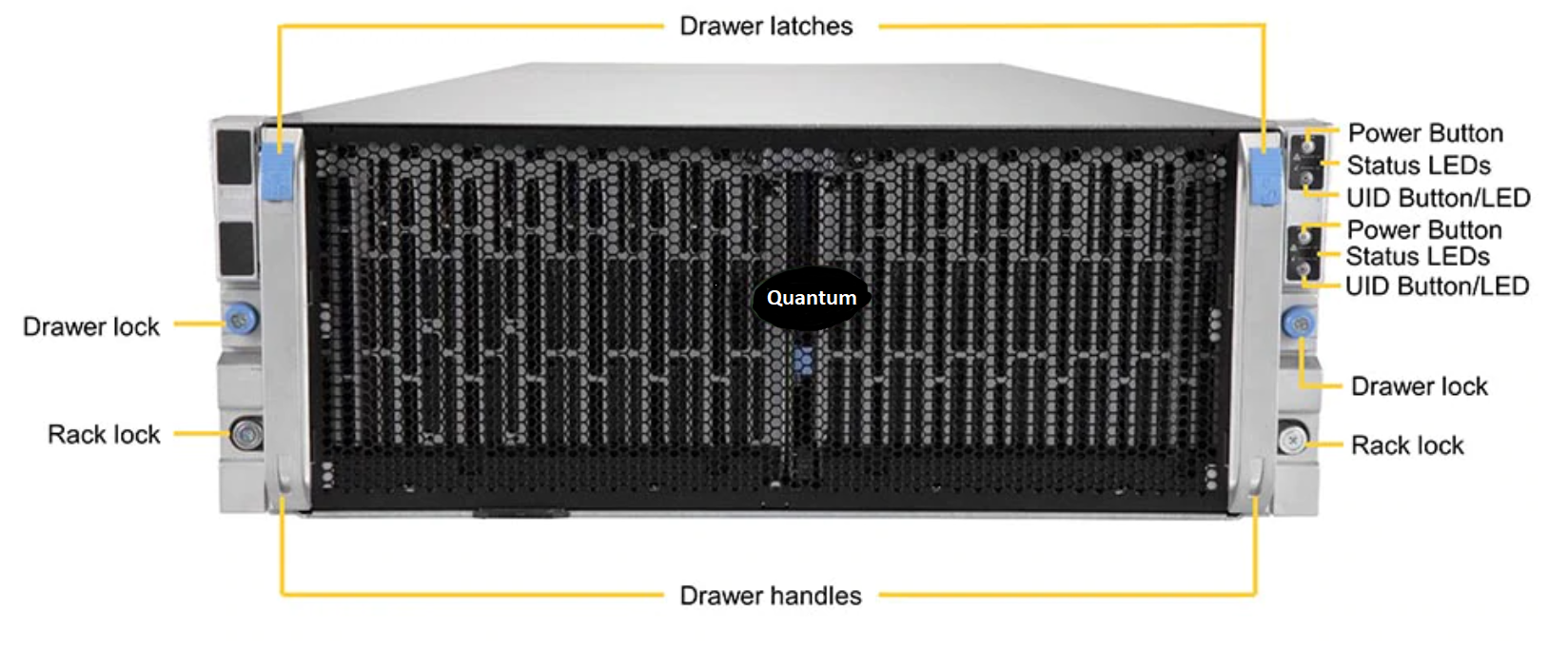
The 4U90 has a control panel for each of the two compute modules. The switches and LED’s located on the control panel are described as follows:

| Item | Feature | Description |
|---|---|---|
| 1 | Power Button/LED | The main power button is used to apply or remove power from the power supply to the server. Turning off system power with this button removes the main power but maintains standby power. To perform many maintenance tasks, you must also unplug system before servicing |
| 2 | NIC LED | Indicates network activity on LAN port 1 when flashing |
| 3 | Universal Information LED |
|
| 4 | UID Button/LED | The Unit ID (UID) button is used to turn on or off the blue UID LED to easily locate the server in racks and server banks. Solid blue indicates the UID was activated locally. Blinking blue indicates UID was activated remotely |
The 4090 Base System Node has a top and bottom removable compute module, each with a removable node (mezzanine) module.
The following table describes the 4U90 Base System Node compute modules and chassis components.
| Description | Quantity |
|---|---|
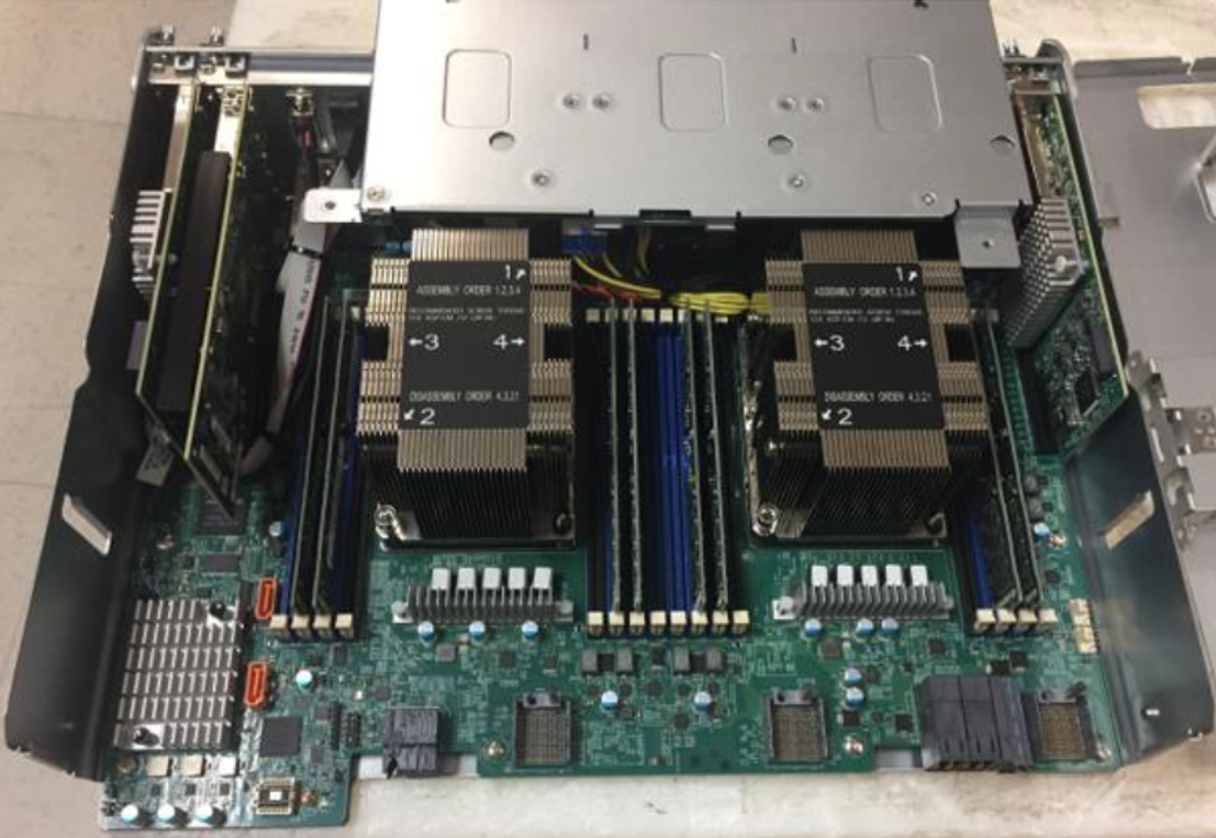
| 2 x 4216 Cascade Lake CPU’s (16 core/2.1GHz/22MB cache/2400MHz mem) | 2 per compute module |
| 32 GB RDIMM memory cards per node | 8 per compute module |
| 3.84 TB NVMe M.2 flash drives | 2 per compute module |
|
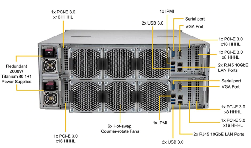
I/O:
|
Per compute module 4 1 4 |
| Hot Swap Redundant 2400 watt power supplies | 2 per chassis |
| Hot Swap Fans | 3 per compute module |
| SAS Expander Modules | 4 chassis |
| 18 TB, 22 TB, or 24 TB HDD's (NLSAS/SATA) | 30/60/90 per chassis |
Compute Module with NODE Module (mezzanine) Attached
There are two compute modules in each 4U90 Twin Server.
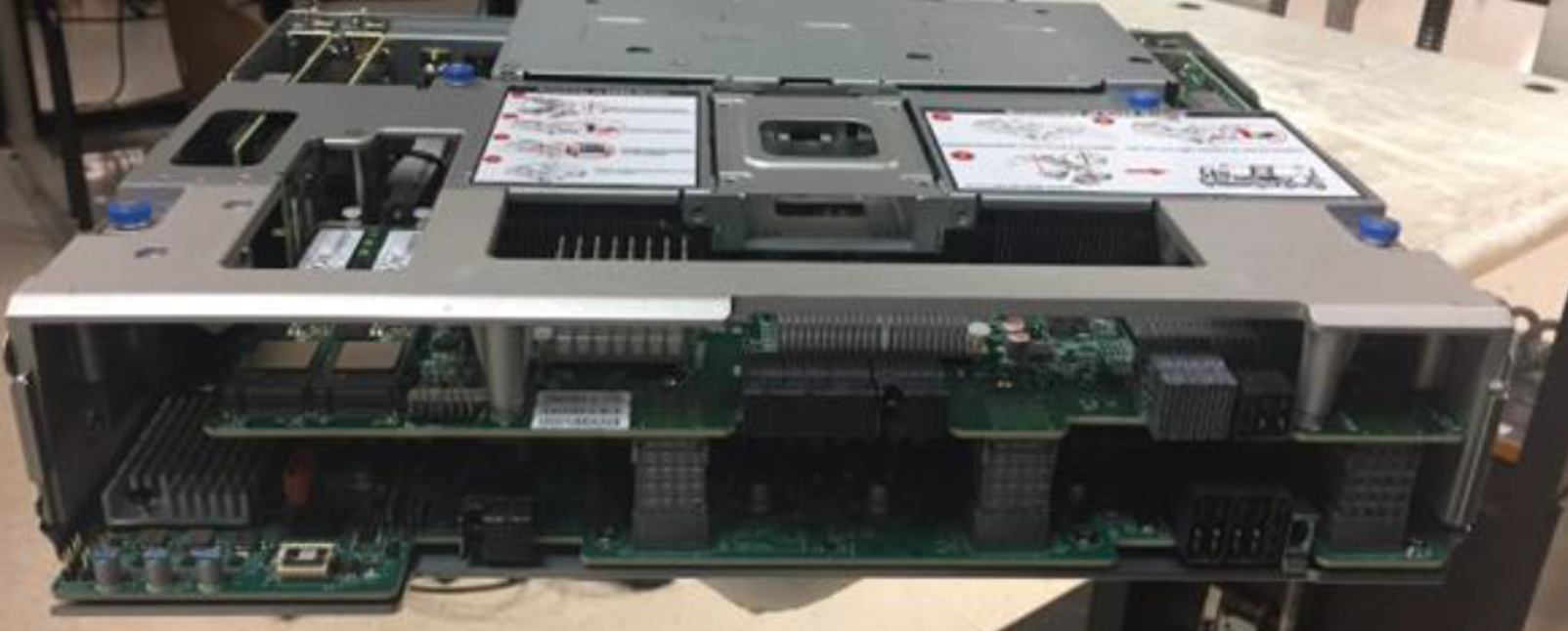
Compute Module with Mezzanine Card Removed
On each compute module is a NODE module (mezzanine) which contains the SAS controllers for high-performing, bandwidth-intensive applications such as video streaming, medical imaging and big data analytics.The instructions for removing and replacing the mezzanine card are printed on a label attached to the mezzanine card itself. These instructions are visible when the compute module has been removed from the chassis.
Figure 1: Mezzanine Card Instructions
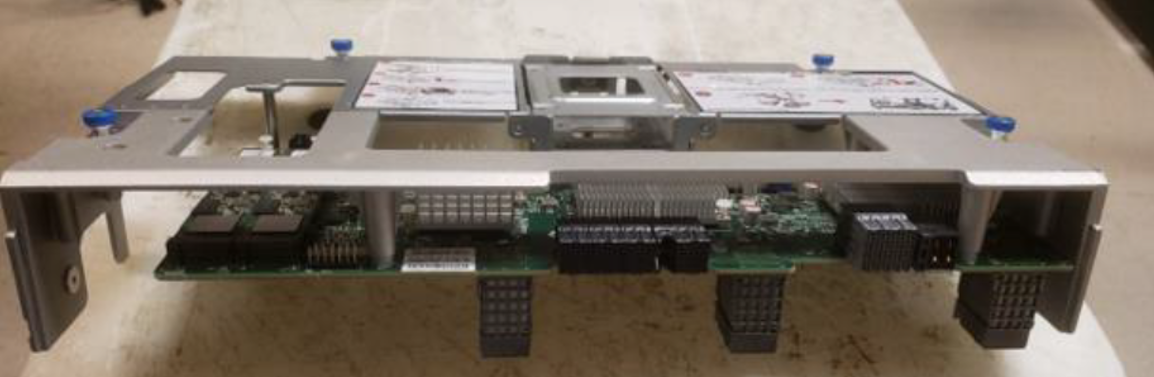
Figure 2: Disassembly of NODE Module (Mezzanine)

Figure 3: Assembly of NODE Module (Mezzanine)

The drive drawer extends to a first stop and then a fully extended position. Pulling the drawer out will extend it to a locked position at the first stop.
A locking handle is located on either side of the chassis front. To unlock the drawer, press the release buttons on the front handles down simultaneously into the unlocked position. Simultaneously pull both handles forward, sliding the HDD drawer out of the storage enclosure, where it will lock in the first position exposing 45 drive slots .
Figure 4: Closeup of drawer latch, control panel and rail lock
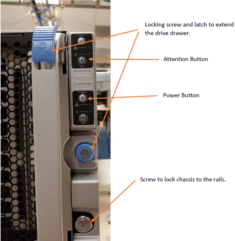
Figure 5: Drive Drawer extended to first stop

There are two latches visible on the sides of the drawer when it has been pulled out to the first stop (one on each side of the drawer) which, when pressed up, will release the drawer locks allowing the drawer to be pulled out to the fully extended position.

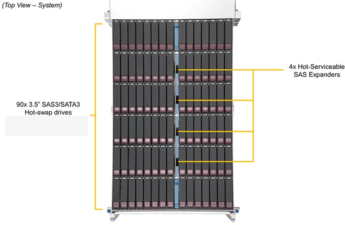
The front 45 drives are controlled by the bottom compute module, while the rear 45 drives are controlled by the top compute module
Figure 6: Drive Drawer Fully Extended top views

Note: An equal number of HDDs must be installed for the top and bottom compute or I/O modules
The 4U90 Base System Node has 4 SAS expander Modules.
Figure 7: Expander modules Installed

Figure 8: Expander Modules Front and Back

Each compute model has three 80mm high-speed, low-vibration, hot-swappable cooling fans.
Figure 9: Fans

Each compute module has a power supply (2 in each cabinet) that provide redundant power in the event one would fail.
Figure 10: Power Supply Modules

| Power Supply Specifications | |
|---|---|
| AC Input | 2000W Output @ 180-240V, 8-6A, 50-60Hz |
| DC Output | +12V/132A |
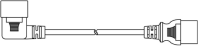
| Cord | Image |
|---|---|
| IEC-60320 C19/C20, 20A - 250V, 5 ft. (1.5 m) |
|
| Width | 17.68 inches (449 mm) |
| Height | 6.97 inches (177 mm) |
| Depth | 42.9 inches (1090 mm) |
| Empty Weight | Approximately 145 lbs (66 kg) |
| Full Weight (with drives) | Approximately 290 lbs (130 kg) |
Important Information
-
Use a lift to install the empty chassis
-
Install the 3.5" HDD's after racking the chassis
Figure 11: Chassis Warning Labels


The 4U90 JBOD chassis features up to 90 hot-swap 3.5" SAS3 hard drives in top-loading drive bays. This design offers extra high density of HDDs per space ratio in a 4U form factor.
The X200 JBOD provides the following features:
-
Support 90 3.5"/2.5" Top Loading SAS3 12Gb/s Hot-Swappable HDDs
-
Six SAS I/O ports (four in two out) on each of two I/O compute modules
-
Dedicated IPMI RJ45 management port
-
Hot-swappable Tool-less Modular Design for Easy Service and Easy Maintenance
-
Two Redundant Titanium 2000W power supplies
-
Three high-speed 80 mm fans per node


| Control Panel Features | ||
|---|---|---|
| Item | Features | Description |
| 1 | Power Button/LED | The main power switch applies or removes primary power from the power supply to the server but maintains standby power. To perform most maintenance tasks, unplug the system to remove all power. |
| 2 | NIC LED | Indicates network activity on the LAN when flashing. |
| 3 | Information LED | Alerts operator to several states, as noted in the following table. |
| 4 | UID Button/LED | The unit identification (UID) button turns on or off the blue light function of the Information LED and a blue LED on the rear of the chassis. These are used to locate the server in large racks and server banks. |
| Information LED | |
|---|---|
| Status | Description |
| Continuously on and red | An overheat condition has occurred. (This may be caused by cable congestion.) |
| Blinking red (1Hz) | Fan failure, check for an inoperative fan. |
| Blinking red (0.25Hz) | Power failure, check for a non-operational power supply. |
| Solid blue | Local UID has been activated. Use this function to locate the server in a rack mount environment. |
| Blinking blue | Remote UID is on. Use this function to identify the server from a remote location. |

| Rear Chassis Features | ||
|---|---|---|
| Item | Feature | Description |
| 1 | Power Supply Modules | Two, redundant hot-swap |
| 2 | Fans | Six, hot-swap |
| 3 | Mini-SAS Ports | Mini-SAS HD ports for internal or external cascading expander combinations |
| 4 | IPMI Port | Networking port used for remote management |
Figure 12: JBOD I/O Ports
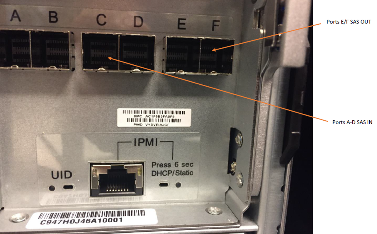
Figure 13: JBOD Rear Panel Buttons/LEDs

|
Rear Panel Buttons/LEDs |
||
|---|---|---|
|
Item |
Features |
Description |
| 1 | UID LED | Turns on (blue) or off when the UID button is pressed. This is used for unit identification. A solid blue light locates the server in a rack mount environment, and a blinking blue light identifies the server from a remote location. |
| 2 | UID button |
The unit identification (UID) button turns on or off the blue UID LED. This is used to locate the server in large racks and server banks. |
| 3 |
IPMI LED |
When the LED is illuminated, the setting is Static. When the LED is off, the setting is DHCP. The default setting is DHCP (off). |
| 4 |
IPMI button |
Press the IPMI button for at least 6 seconds to change to Static or DHCP. Rear Chassis Features |
The 4U90 has a removable top and bottom I/O module.
Figure 14: I/O Module - Front

Figure 15: I/O Module - Back

Each JBOD I/O module has four hot swap-able fans.
Figure 16: Front and Back
Each I/O module has a power supply (2 in each cabinet) that provide redundant power in the event one would fail.
Figure 17: JBOD Power Supply
| Power Supply Specifications | |
|---|---|
| AC Input | 2000W Output @ 180-240V, 8-6A, 50-60Hz |
| DC Output | +12V/132A |
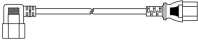
| Cord | Image |
|---|---|
| IEC-60320 C13/C14, 13A - 250V, 5 ft. (1.5 m) |
|
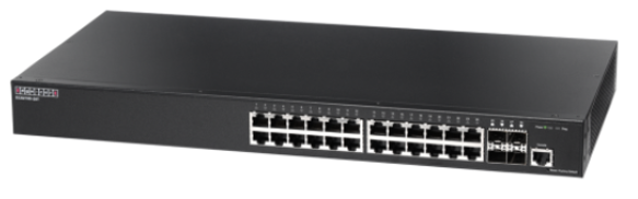
Two Quantum-supplied (pictured below) or customer-supplied data switches are required to provide the back-end network for the X200. Additional data switches may be required depending on the size of the deployment.
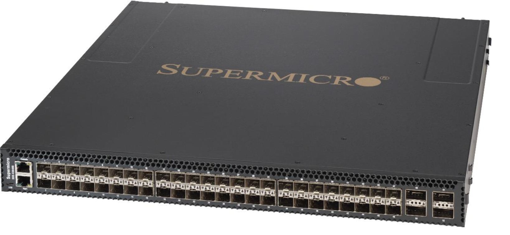

One Quantum-supplied (pictured below) or customer-supplied IPMI switch per rack is required to provide the remote management network for the compute and I/O modules.

| Configuration |
200V Current |
240V Current |
BTU/hr | Power Req Operating |
Power Req In Rush |
|---|---|---|---|---|---|
| Twin Server with 90 drives | 9.7 | 8.1 | 6583 | 1930W | 2500W |
|
Twin JBOD with 90 drives |
5.2 | 4.2 | 3500 | 1613W | 2090W |
|
10/25GbE Data Switch |
2.1 | 1.9 | 1432 | 420W | |
|
1GbE IPMI Switch |
0.1 | 0.1 | 68 | 20W | |
|
Maximum Configuration Operating |
22.5kW |
This section gives a high-level overview of the requirements and quantities of networking components for X200 systems, mainly for planning purposes. Note that the X200 Sizing Tool also reports this output when sizing a system.
The networking setup for a High-Available ActiveScale X200 system consists of several different networks and networking components. The public traffic to and from the system goes via 2 networks which usually have their own dedicated switch(es). The internal traffic is also handled by 2 dedicated and independent networks, where each network typically has dedicated switches to guarantee High Availability when a switch goes down. One of the internal networks also hosts the IPMI connectivity for all the nodes and JBODs. These are usually interconnected via a dedicated IPMI switch, which is then connected to one of the internal switches as well.
A high-level overview of the physical networking layout for each 4U90 Twin Server within an ActiveScale X200 system is shown in this picture:
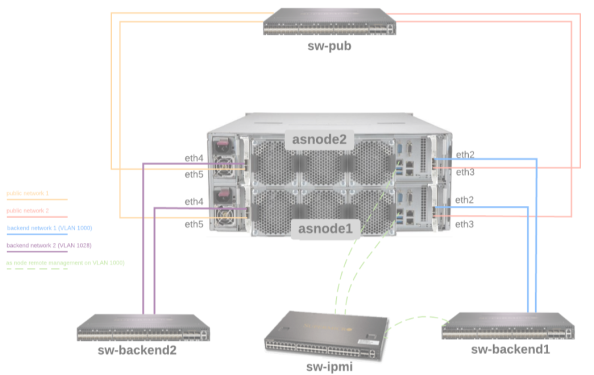
To accommodate the X200 internal traffic 10/25 GbE switches are required. 25 GbE is recommended, since 10 GbE will result in lower performance of the ActiveScale X200 system.
All the internal traffic will be spread across 2 independent networks for HA reasons. Therefore, an even number of 10/25 GbE switches is recommended.
Data Switch Requirements
These data switches need to have the following requirements:
-
Layer-3 switch with full non-blocking backplane, support for static IP routing, 802.1Q (tagged VLANs), port-based VLANs and Telnet/SSH for remote login and management.
-
Each 4U90 Twin Server internally has 2 physical nodes, where each one has 4 10/25GbE network ports. Half of the ports of each physical node will be used for internal traffic, so we need 4 10/25GbE ports per 4U90 Twin Server to be connected to the internal data traffic switches. If 2 switches are used for internal connectivity, then half of the connections need to go to switch 1 and the other half to switch 2. If only a single switch is used (not recommended), then all 4 internal connections need to go to this single switch.
These ports need to support either 10 or 25 GbE (via DAC cables or SFP+/SFP28 optical transceivers).
Note: X200 supports Long-Range/Single-Mode or Short-Range/Multi-Mode SFPs for use on public network connections.
-
During the ActiveScale software installation, the VM installer will have to be connected to the 1st internal network using a connection that offers a network speed of 1 GbE or better. Therefore, 1 additional switch port should be foreseen in the 1st internal network. This port will only be used during the ActiveScale software installation and can be repurposed when the install is complete.
-
When there will be more than 2 internal data traffic switches, at least 2 ports per switch need to be configured as scale-out ports (to provide interconnectivity between the switches).
-
These scale-out ports need to support either 40/100GbE (recommended, via DAC cables or QSFP/QSFP28 optical transceivers), or 10/25GbE (via DAC cables or SFP+/SFP28 optical transceivers).
-
For performance reasons it might be required to have more than 2 ports per switch configured as scale-out ports.
-
-
For 3-Geo deployments at least 1 port per switch needs to be used for inter-geo connectivity.
-
These inter-geo connectivity ports need to support either 40/100GbE (recommended; via DAC cables or QSFP/QSFP28 optical transceivers), or 10/25GbE (via DAC cables or SFP+/SFP28 optical transceivers).
-
For performance reasons it might be required to have more than 1 port per switch configured as inter-geo connectivity ports.
-
-
The IPMI switches will need to be connected to the first internal data traffic network. 1 port per IPMI switch will have to be connected, as explained below.
IPMI Switch Requirements
To accommodate the X200 internal IPMI traffic, RJ45-based 1GbE switches are required. 1GbE is recommended, but other network speeds should also work fine.
These IPMI switches need to have the following requirements:
-
Software features to support Layer2/Layer-3 networking including VLAN, Telnet/SSH for remote login and management, …
-
The system needs a total of 2 RJ45 ports per 4U90 Twin Server on the IPMI switches.
-
The system needs a total of 2 RJ45 ports per 4U90 Twin JBOD on the IPMI switches.
-
Each IPMI switch needs 1 port for connectivity to the internal data switches of the first internal data traffic network.
To accommodate the public traffic 10/25GbE switches are required. 25GbE is recommended, since 10GbE will result in lower performance of the system. If NIC bonding will be used on the public interfaces, then these switches need to support Dynamic link aggregation (802.3ad, LACP).
The public traffic can be spread across multiple switches for HA reasons, or only a single switch can be used. The same switches as for the internal traffic can be used, or different switches can be used.
Note: X200 supports Long-Range/Single-Mode SFPs for use on public network connections.
These switches need to have the following requirements:
-
The system needs a total of 4 10/25GbE ports per 4U90 Twin Server on the public switches.
These ports need to support either 10/25GbE (via DAC cables or SFP+/SFP28 optical transceivers).
-
The ports on the switch connected to the ActiveScale public interfaces should be able to receive UNTAGGED traffic, because ActiveScale public interfaces can’t be configured to tag traffic for a certain VLAN. Therefore, these switch ports should be set in access mode (not trunk):
switchport mode access
The table below contains the number of required switch ports for some common 1-Geo X200 configurations:
| X200 Configuration | Switch Ports for Internal Network 1 | IPMI Ports (Internal Network 1) | Switch Ports for Internal Network 2 | Switch Ports for Public Traffic |
|---|---|---|---|---|
| 3 x 4U90 Twin Server | 8 x 10/25 GbE | 6 x 1 GbE | 6 x 10/25 GbE | 12 x 10/25 GbE |
| 3 x 4U90 Twin Server + 3 x 4U90 JBOD | 8 x 10/25 GbE | 12 x 1 GbE | 6 x 10/25 GbE | 12 x 10/25 GbE |
| 6 x 4U90 Twin Server | 14 x 10/25 GbE | 12 x 1GbE | 12 x 10/25 GbE | 24 x 10/25 GbE |
| 30 x 4U90 Twin Server (using 48-port 10/25 GbE switches and 24-port 1 GbE switches) | 64 x 10/25 GbE (distributed over 2 48-port switches) 2 x 40/100 GbE (to interconnect these 2 switches) | 60 x 1GbE (distributed over 3 24-port switches) | 60 x 10/25 GbE (distributed over 2 48-port switches) 2 x 40/100 GbE (to interconnect these 2 switches) | 120 x 10/25 GbE |
The table below contains the number of required switch ports for some common 3-Geo X200 configurations:
| X200 Configuration | Switch Ports for Internal Network 1 | IPMI Ports (Internal Network 1) | Switch Ports for Internal Network 2 | Switch Ports for Public Traffic |
|---|---|---|---|---|
| 9 x 4U90 Twin Server (3 x 4U90 Twin Server per Geo) | 22 x 10/25 GbE (8 in 1 Geo, 7 in other Geo’s) | 18 x 1 GbE (6 per Geo) | 18 x 10/25 GbE (6 per Geo) | 36 x 10/25 GbE (18 per Geo) |
| 9 x 4U90 Twin Server + 9 x 4U90 JBOD (3 x 4U90 Twin Server + 3 x 4U90 JBOD per Geo) | 22 x 10/25 GbE (8 in 1 Geo, 7 in other Geo’s) | 36 x 1 GbE (12 per Geo) | 18 x 10/25 GbE (6 per Geo) | 36 x 10/25 GbE (18 per Geo) |
| 18 x 4U90 Twin Server (3 x 4U90 Twin Server per Geo) | 40 x 10/25 GbE (14 in 1 Geo, 13 in other Geo’s) | 36 x 1GbE (12 per Geo) | 36 x 10/25 GbE (12 per Geo) | 72 x 10/25 GbE (24 per Geo) |
| 90 x 4U90 Twin Server (30 x 4U90 Twin Server per Geo; using 48-port 10/25 GbE switches and 24-port 1 GbE switches) | 190 x 10/25 GbE (64 in Geo 1, 63 in other Geo’s; distributed over 2 48-port switches per Geo) 12 x 40/100 GbE (4 per Geo; to interconnect the switches and for inter-geo connectivity) | 180 x 1GbE (60 per Geo; distributed over 3 24-port switches per Geo) | 180 x 10/25 GbE (60 per Geo; distributed over 2 48-port switches per Geo) 12 x 40/100 GbE (4 per Geo; to interconnect the switches and for inter-geo connectivity) | 360 x 10/25 GbE (120 per Geo) |
X200 Rack Requirements
The ActiveScale X200 storage system is designed to mount in 19” racks that meet the EIA 310 Rack Standard.
| Requirement | Description |
|---|---|
| Minimum Rack Depth | The minimum recommended rack depth required is 1200 mm (47.24”) when the rack has doors. This depth allows for clean and efficient cable routing between the nodes and enclosures. It also provides extra space for rear mount vertical power distribution units (PDUs), which Quantum recommends. |
| Rail Kits | The X200 chassis rail kits work with the EIA 310 Rack Standard and must have square, vertical rack mounting flanges. Round or threaded holes are not supported. |
| Rack Spacing |
|
| Rack Size | Each node consumes 2U of rack space and each enclosure consumes 4U of rack space. |
Rack Installation Requirements
-
Ensure that the leveling jacks on the bottom of the rack are extended to the floor so that the full weight of the rack rests on them.
-
In single rack installations, stabilizers should be attached to the rack. In multiple rack installations, the racks should be coupled together.
-
Always make sure the rack is stable before extending a server or other component from the rack.
-
You should extend only one server or component at a time; extending two or more simultaneously may cause the rack to become unstable.
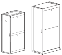
Quantum recommends the use of the NetShelter SX Series Cabinet for the ActiveScale X200 system. This rack is 750 mm wide x 1200 mm deep.
Figure 18: NetShelter SX Cabinet

|
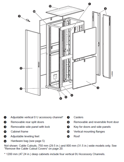
Figure 19: APC NetShelter SX Cabinet
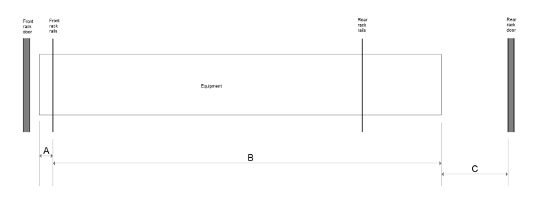
4U90 Twin Base Server Chassis
| Item | Description | Dimension |
|---|---|---|
| A | Distance between front of node and front rack rails |
2.03” 51 mm |
| B | Distance between front rack rails and the rear of the node |
42.93” 1091 mm |
| C | Amount of clearance required behind the node in order to accommodate equipment handles, transceivers, cables, cable management arms, etc. |
1.12"¹ 28.5 mm¹ |
4U90 JBOD
| Item | Description | Dimension |
|---|---|---|
| A | Distance between front of node and front rack rails |
2.03” 51 mm |
| B | Distance between front rack rails and the rear of the node |
41.6” 1057 mm |
| C | Amount of clearance required behind the node in order to accommodate equipment handles, transceivers, cables, cable management arms, etc. |
2.46”¹ 62.5 mm¹ |
| Rack | Configuration | Weight |
|---|---|---|
| Base Rack |
|
3,145 lbs 1427 kg 1586 kg/m² |
|
Expansion Rack (Expanded to Base Rack Above) |
|
3,105 lbs 1408 kg 1564 kg/m² |
| Rack | Configuration | Weight |
|---|---|---|
| Base Rack |
|
2,815 lbs 1277 kg 1419 kg/m² |
|
Expansion Rack (Expanded to Base Rack Above) |
|
3,336 lbs 1513 kg 1681 kg/m² |
|
|
Server Technology PRO2 Switched PDU (PDF)
|
-
4 x 3 phase Delta 208V 60A intelligent/ipmi
-
4 x 3 phase Wye 400V 32A intelligent/ipmi
-
JBOD should be installed directly above corresponding compute node
-
Cannot support JBODs in separate rack from Twin compute nodes (due to SAS cable max length limit).
-
Each Expansion JBOD comes with 1m SAS cables