ActiveScale Switch Configuration
This document complements the X200 networking and scale out guides with additional information on how to correctly configure the ToR (Top of Rack) and IPMI switches. X200/P200 configurations are divided into columns (also called an erasure encoding domain), which is a set of nodes (usually a multiple of 3 X200 twin servers or 3 P200 servers) that can be seen as a single independent unit. Scale-out of X200/P200 consists of adding another column. An X100/P100 can also be scaled out with X200/P200 by connecting the ToR switches via Scale out-uplinks.
The recommended SuperMicro SSE-F3548SR ToR switches used for X200/P200 have 48 SFP28 ports and 6 QSFP28 ports. This layout is what is assumed to be used in this guide.
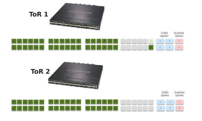
The general layout for X200 ToR switches is as follows:
| Ports | Description |
|---|---|
| 1-36 |
These ports are connected to the X200 combined server nodes, so up to 36 nodes can be connected to a single ToR switch pair. For X200 configurations, a ToR switch-pair can serve anything between a single 18-twin column (with or without JBODs (just a bunch of disks)) and 36 /6 = 6 columns consisting of 3 twin servers (with or without JBODs). The port configuration thus depends on the number of independent columns (scale out), and the number of nodes in each column. There will be 1 VLAN configured per column. The default VLANs for the private network 1 (ToR 1 and IPMI (X200 only)) start at 1000 for the first installed column and go all the way up to 1127 for future expansion columns (Scale Up). |
| 37-46 (grey) | These ports are used for 25 Gb/s 3-GEO uplinks if no 40Gb/s or 100Gb/s (using QSPF+/QSFP28) is available, or used as spares to deal with switchport failures. |
| 47 (labeled “I”) | This port is used as the IPMI uplink for X200. This is a trunk port that forwards all used private network 1 VLANs (in the range 1000-1127) to the connected IPMI switch. |
| 48 (labeled “V”) | This port is reserved as a port for the laptop that runs the VM (Virtual Machine) installer during installation. |
The QSFP28 ports are used for uplinks in 3-GEO and Scale out systems (with X100 or setups beyond a total of 36 nodes). They are configured in 2 Link Aggregation groups, one for 3-GEO uplinks and one for Scaleout. The number of ports in these groups can be configured per customer requirements. The default as drawn above is to use 4 ports for 3-GEO uplinks and 2 ports for Scale out.
The recommended Edge-Core ECS2100-28T 24 port 1GbE IPMI switches used for X200, have 24 SFP28 ports and 6 QSFP28 ports. This layout is what is assumed to be used in this guide.
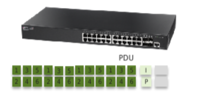
The IPMI switches are only used for X200. There is always one IPMI switch per rack, and potentially additional switches for Cold Storage.
Ports 1-20 are used for the IPMI of the twin servers and JBOD expansions. This can support 10 Twin servers or 5+5 Twin/JBOD pairs in a single rack. Ports 21-24 are reserved for the (up to 4) PDUs in the rack. SFP port 25 (Labeled “I”) is used to connect to ToR1 port 47 (first rack). In a scaled out environment, each additional rack will chain the IPMI switches via SFP port 26 (labeled “P”) to SFP port 25 of the next rack. For Cold storage IPMI, an RJ45 connector is used to connect the dedicated Cold Storage IPMI switch to the ActiveScale IPMI switch.
The IPMI ports need to be configured so that they correspond with the private 1 VLANs of the server interfaces.
This guide walks to a configuration for the ToR switches (assuming the management port and passwords are pre-configured in the factory). First login to the switch and go into configuration mode.
Interconnect1# config
Interconnect1(config)#
VLAN Configuration
Add the VLANs that will reside on the switch. Default VLANs for a single GEO start at 1000 for ToR1, and 1128 for ToR2. See the networking guide for more information.
Interconnect1(config)# vlan 1000-1005
Interconnect1(config-vlan)# exit
Interconnect1(config)# exit
Add an IP address so we can manage the switch from each of the needed VLANs, for instance:
Interconnect1(config)# interface vlan 1000
Interconnect1(config-if)# ip address 172.20.0.200 255.255.255.0
Interconnect1(config-if)# description Column_0_Private_VLAN_1
Interconnect1(config-if)# exit
Interconnect1(config)# interface vlan 1001
Interconnect1(config-if)# ip address 172.20.1.200 255.255.255.0
Interconnect1(config-if)# description Column_1_Private_VLAN_1
Interconnect1(config-if)# exit
Interconnect1(config)#
...
Port Configuration
The ports for the servers can be configured per VLAN, for instance:
Interconnect1(config)# interfaces range Fx 0/1-6
Interconnect1(config-if)# description Column_0_Private_VLAN_1
Interconnect1(config-if)# switchport mode access
Interconnect1(config-if)# switchport access vlan 1000
Interconnect1(config-if)# exit
Interconnect1(config)# interfaces range Fx 0/7-12
Interconnect1(config-if)# description Column_1 Private_VLAN_1
Interconnect1(config-if)# switchport mode access
Interconnect1(config-if)# switchport access vlan 1001
Interconnect1(config-if)# exit
Interconnect1(config)#
In addition, we need to configure the port for the installer. Default is port 48. The VLAN needs to be set to the VLAN of the column to be installed.
Interconnect1(config)# interface Fx 0/48
Interconnect1(config-if)# description Installer_1G_Port
Interconnect1(config-if)# no fec-mode
Interconnect1(config-if)# no negotiation
Interconnect1(config-if)# speed 1000
Interconnect1(config-if)# switchport mode access
Interconnect1(config-if)# switchport access vlan 1000
Interconnect1(config-if)# exit
Interconnect1(config)#
We also need to configure the IPMI uplink on port 47 (used only in case of X200). This port needs to trunk all VLANs towards the IPMI switch (VLAN tagging):
Interconnect1(config)# interface Fx 0/47
Interconnect1(config-if)# description IPMI_1G_Uplink
Interconnect1(config-if)# no fec-mode
Interconnect1(config-if)# no negotiation
Interconnect1(config-if)# speed 1000
Interconnect1(config-if)# switchport mode trunk
Interconnect1(config-if)# switchport trunk allowed vlan 1000-1005
Interconnect1(config-if)# exit
Interconnect1(config)#
The ToR switches have spanning tree enabled, which for X200 we do not need. Turn this off:
Interconnect1(config)# no spanning-tree
Set the NTP server to the system nodes. Use correct IP address for your installation:
Interconnect1(config)# ntp server 172.20.0.1 prefer
Interconnect1(config)# ntp server 172.20.0.2
Interconnect1(config)# ntp server 172.20.0.3
Interconnect1(config)# ntp enable
Finally, save the switch configuration:
Interconnect1(config)# exit
Interconnect1# write startup-config
Reboot the switch and verify the switch configuration is saved after reboot.
Interconnect1# reload
Note: The CLI for the IPMI switches is a little bit different than for the TOR switches, but otherwise the configuration is very similar to the base configuration for the ToR switches.
VLAN Configuration
Vty-1#config
Vty-1(config)#vlan database
Vty-1(config-vlan)# vlan 1000-1005
Vty-1(config-vlan)# exit
Vty-1(config)#interface vlan 1000
Vty-1(config-if)#ip address 172.20.0.181 255.255.255.0
Vty-1(config-if)#exit
Vty-1(config)#interface vlan 1001
Vty-1(config-if)#ip address 172.20.1.181 255.255.255.0
Vty-1(config-if)#exit
Vty-1(config)#
...
Port Configuration
Vty-1(config)#interface ethernet 1/1-6
Vty-1(config-if)# switchport mode access
Vty-1(config-if)# description Column_0_IPMI
Vty-1(config-if)# switchport allowed vlan add 1000 untagged
Vty-1(config-if)# exit
Vty-1(config)#interface ethernet 1/7-12
Vty-1(config-if)# switchport mode access
Vty-1(config-if)# description Column_1_IPMI
Vty-1(config-if)# switchport allowed vlan add 1001 untagged
Vty-1(config-if)# exit
...
The uplink (port 25) should be a trunk port.
Vty-1(config)# interface ethernet 1/25
Vty-1(config-if)# description IPMI_Uplink
Vty-1(config-if)# switchport allowed vlan add 1000-1005 tagged
Vty-1(config-if)# switchport mode trunk
Vty-1(config-if)# exit
Vty-1(config)# exit
Finally, save the configuration:
Vty-1# copy running-config startup-config
The switches in 3-GEO are configured as for a single GEO, but will need additional configuration to for the uplinks, with IP routing entries.
Port Channel Configuration
By default, we configure the uplinks using bonded ports. This will use a customer VLAN in each GEO, e.g. 164, which we need to add to the switch config:
Interconnect1(config)# vlan 164
Interconnect1(config-vlan)# exit
Now, create the bonded interface (port-channel):
Interconnect1(config)# interface port-channel 1
Interconnect1(config-if)# description 3-GEO_uplink
Interconnect1(config-if)# switchport mode access
Interconnect1(config-if)# mtu 9000
Interconnect1(config-if)# switchport access vlan 164
Interconnect1(config-if)# exit
Now, the uplink ports can be added to this port-channel, for instance, to add the 100G ports 1-4:
Interconnect1(config)# interface range Cx 0/1-4
Interconnect1(config-if)# description ActiveScale_UPLINK
Interconnect1(config-if)# mtu 9000
Interconnect1(config-if)# channel-group 1 mode active
Interconnect1(config-if)# exit
Finally, the switches need 2 routing entries towards the other GEOs. Assuming we use the default IP addressing scheme for activescale, and the customer router in GEO1 has IP address 10.100.11.254:
Interconnect1(config)# ip route 172.22.0.0 255.255.224.0 10.100.11.254
Interconnect1(config)# ip route 172.23.0.0 255.255.224.0 10.100.11.254
Note that the customer routers also need similar routing entries towards the other GEO’s.
n scaleout configuration, we also use 100G QSFP ports towards the X100, configured in 40G mode, which will use another VLAN on the interconnection link. Example VLANs are to use: XY where X is the TOR (1 or 2) and Y is the GEO (0,1,2). But the choice is arbitrary, as long as it is not otherwise in use on the switch or the X100 switch. The interconnection link also needs an IP subnet for routing, e.g. 172.16.XY.0/24 (this can be a much smaller subnet, but we have noticed issues with smaller subnets on the switch. This should not impact the customer in any way as this is subnet is internal to ActiveScale).
So, for X200 ToR 1, Site 1:
Interconnect1(config)# vlan 10
Interconnect1(config-vlan)# exit
Interconnect1(config)# interface vlan 10
Interconnect1(config-if)# ip address 172.16.10.2 255.255.255.0
Interconnect1(config-if)# exit
Next, create the bonded interface (port-channel) for the scale out:
Interconnect1(config)# interface port-channel 2
Interconnect1(config-if)# description scaleout_uplink
Interconnect1(config-if)# switchport mode access
Interconnect1(config-if)# mtu 9000
Interconnect1(config-if)# switchport access vlan 10
Interconnect1(config-if)# exit
Now, the uplink ports can be added to this port-channel, for instance, to add the 100G ports 5-6:
Interconnect1(config)# interface range Cx 0/5-6
Interconnect1(config-if)# description ActiveScale_UPLINK
Interconnect1(config-if)# no fec-mode
Interconnect1(config-if)# no negotiation
Interconnect1(config-if)# speed 40000
Interconnect1(config-if)# mtu 9000
Interconnect1(config-if)# channel-group 2 mode active
Interconnect1(config-if)# exit
Add a route to the X100’s scaleout network (VLANs 110/120/130).
Interconnect1(config)# ip route 172.16.110.0 255.255.255.0 172.16.10.1
Additional routes in case of 3-GEO need to go over the customer router:
Interconnect1(config)# ip route 172.16.120.0 255.255.255.0 10.100.11.254
Interconnect1(config)# ip route 172.16.130.0 255.255.255.0 10.100.11.254
Save the config
Interconnect1(config)# exit
Interconnect1# write startup-config
The X100 switch will also need additional configuration:
To go into enable mode:
(Site1_Storage_Interconnect1) >enable
(Site1_Storage_Interconnect1) #
Add the VLAN that is to be used on the X100-X200 interconnection link, e.g. 10, and optionally give it a name.
(Interconnect1) # vlan database
(Interconnect1) (Vlan)# vlan 10
(Interconnect1) (Vlan)# vlan routing 10 5
(Interconnect1) (Vlan)# vlan name 10 X200_Scaleout
(Interconnect1) (Vlan)# exit
(Interconnect1) #config
(Interconnect1) (Config)# interface vlan 10
(Interconnect1) (Interface vlan 110)# ip address 172.16.10.1 255.255.255.0
(Interconnect1) (Interface vlan 110)# exit
Create a bonded interface, these are named interface 3/x in the CLI. So, the first is 3/1 and configured as lag x. Here, we add QSFP+ interfaces 0/50 and 0/52 to a bond:
(Interconnect1) (Config)# interface 0/50
(Interconnect1) (Interface 0/50)# addport 3/1
(Interconnect1) (Interface 0/50)# exit
(Interconnect1) (Config)# interface 0/52
(Interconnect1) (Interface 0/52)# addport 3/1
(Interconnect1) (Interface 0/52)# exit
(Interconnect1) (Config)# interface lag 1
(Interconnect1) (Interface lag 1)# description Scaleout_uplink_X200
(Interconnect1) (Interface lag 1)# no port-channel static
(Interconnect1) (Interface lag 1)# port-channel load-balance 4
(Interconnect1) (Interface lag 1)# switchport mode access
(Interconnect1) (Interface lag 1)# switchport access vlan 10
(Interconnect1) (Interface lag 1)# vlan acceptframe vlanonly
(Interconnect1) (Interface lag 1)# vlan ingressfilter
(Interconnect1) (Interface lag 1)# exit
With the interface configured, we need to enable IP routing and add the IP routes.
(Interconnect1) (Config)# ip routing
(Interconnect1) (Config)# ip route 172.20.0.0 255.255.224.0 172.16.10.2
For 3-GEO scaled out setups, we will need routes to the other GEOs too (this can be over the X200 ToR, or, better, the customer gateway to keep the routes symmetrical):
(Interconnect1) (Config)# ip route 172.21.0.0 255.255.224.0 172.16.10.2
(Interconnect1) (Config)# ip route 172.22.0.0 255.255.224.0 172.16.110.254
(Interconnect1) (Config)# ip route 172.23.0.0 255.255.224.0 172.16.110.254
(Interconnect1) (Config)# exit
Save the switch config:
(Interconnect1) # wr mem
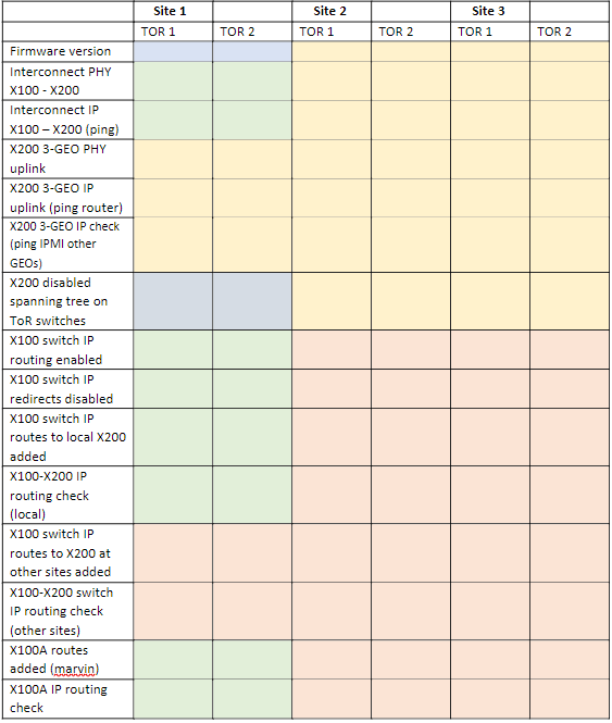
Legend:
Blue - Always needed
Yellow - Needed with 3-GEO
Green – Needed with Scale Out
Red – Only needed for 3-GEO Scale Out
To show the configuration of the switch:
Interconnect1# show running-config
For a specific interface, for instance Fx 0/6:
Interconnect1# show running-config interface Fx 0/6
Or to get more details on all settings:
Interconnect1# show tech-support
Using 25Gb SFP28 instead of DAC cables may require turning auto-negotiation off:
Interconnect1# config
Interconnect1(config)# interface Fx 0/1
Interconnect1(config-if)# no negotiation
Interconnect1(config-if)# no fec
Interconnect1(config-if)# speed 25000