Replace Drives
The 4U90 twin server chassi supports 90 3.5" hard drives. The drives can be removed without powering down the system. In addition, both servers support two 2.5” SATA drives and (optional) four U.2 NVME drives at the rear of the chassis.
Caution: Use extreme caution when removing or replacing disk drives near the expansion modules. There is very little distance between the drive and the expansion module and damage may occur if care isn't taken.
![]()
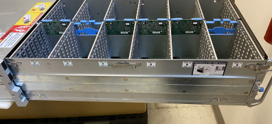
The drives are mounted in drive carriers to simplify their installation and removal from the chassis.
Note: All drive slots in the chassis should have drive carriers installed. The carriers help promote proper airflow through the drive bays.
Caution: Except for short periods of time, such as swapping hard drives, do not operate the server with the hard drive bays empty. The carrier design promotes proper air flow through the chassis.
-
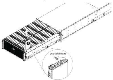
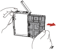
Pull the storage enclosure forward out of the chassis.
-
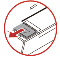
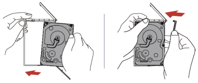
Slide the release button on the drive carrier, which opens the carrier handle.
-
Use the drive carrier handle to pull the drive up out of the chassis.
With the drive carrier removed from the storage compartment:
-
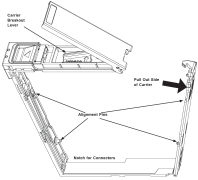
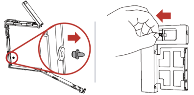
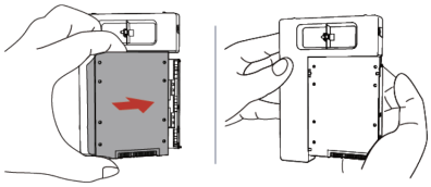
Under the main the carrier handle, find and then lift the breakout lever and pull out the side of the carrier.
-
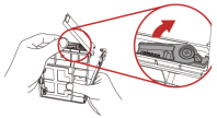
Remove the dummy drive from the carrier.
-
Insert the hard drive into the drive carrier. Orient the drive by matching the two alignment pins on the side and by noting the notch in the carrier for the HDD connectors. Close the side of the carrier until it snaps in place.
-
Slide the carrier assembly into its spot in the chassis until it clicks into place. Then press the release button and push the drive carrier handle down into the locked position.
With the drive carrier removed from the storage compartment:
-
Remove the pin from the carrier side and place it in the dummy tray for later use.
-
Insert the hard drive into the HDD dummy until it locks into place.
-
Slide the carrier assembly into its spot in the chassis until it clicks into place. Then press the release button and push the drive carrier handle down into the locked position.
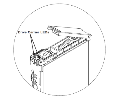
Each hard drive carrier has two LED indicators: an activity indicator and a status indicator. The status indicator functions in RAID configurations. For non-RAID configurations, it remains off. See the table below for details.
|
Hard Drive Carrier LEDIndicators |
|||
|---|---|---|---|
|
Color |
Blinking Pattern |
Behavior for Device |
|
|
Activity LED |
Blue |
Solid on |
Indicates a SAS drive |
|
Blue |
Off |
Indicates a SATA drive |
|
|
Blue |
Blinking |
Drive is actively being accessed |
|
|
Status LED |
Red |
Solid on |
Drive failed |
|
Red |
Blinking at 1Hz |
RAID is rebuilding |
|
|
Red |
Blinking at 3Hz |
Indicates a hot spare |
|
|
Red |
Blinking at 4Hz |
Locates a drive |
|
|
Red |
Off |
Idle |
|
Note: Enterprise level hard disk drives are recommended for use in chassis and servers. For information on recommended HDDs, visit the Quantum website and check the "Drive Options" in the product webpage.
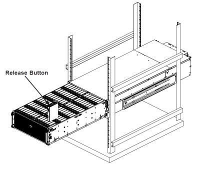
-
Press the release buttons on both of the front handles downward simultaneously and pull the chassis handles forward from the rack.
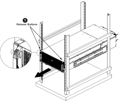
Caution: Stability hazard. The rack stabilizing mechanism must be in place, or the rack must be bolted to the floor before you slide the unit out for servicing. Failure to stabilize the rack can cause the rack to tip over. Slide rail mounted equipment is not to be used as a shelf or a work pace.
-
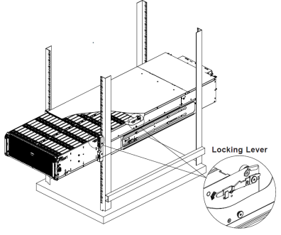
Pull open the chassis so that a locking lever on each side of the chassis aligns with the front of the chassis cover and front of the rack, then press the lever down on each side to lock the open part of the chassis in place.
-
HDDs and their carriers can be loaded into the chassis, or removed from the chassis by pressing their release buttons to eject their handles and then pulling the drives out by the handles.
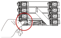
The disk locations are important to know when determining which disk drives need to be replace. The disk layout is indicated as follows:
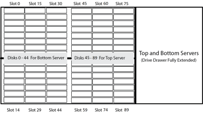
Note: The drives should be installed evenly for the top and bottom servers starting at slot 0 and slot 45.
Caution: The blank drive carrier should be installed in every blank drive slot for air flow management.
Hot Swapping a Disk Drive
Some precautionary steps should be taken in the ActiveScale software for multi-disk replace on an X200 system to avoid a blockstores machine configuration error which unnecessarily causes TASK_FAILED events and ‘machine configure’ task failures.
Note: Hot swap will still work without these extra steps but will give a TASK_FAILED event and ‘machine configure’ task failures. The disk replace will still succeed and complete in the end.
Perform the following to eliminate errors when hot swapping more than one disk drive.
-
From the GUI, shut down the system where you wish to replace more than one disk at a time.
-
Follow the disk replace instructions to replace all disks.
-
Turn on the system again.